1
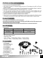
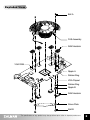
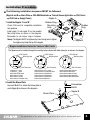
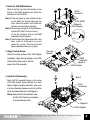
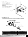
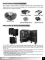
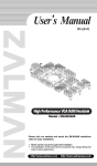
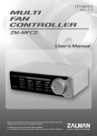
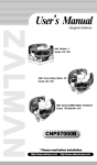
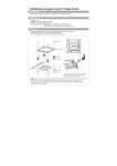
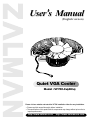
User’
s Manual
(English version)
Quiet VGA Cooler
Model : VF700-Cu(AlCu)
Please visit our website and watch the VF700 installation video for easy installation.
※ Please read this manual thoroughly before installation.
※ The specifications of this product and its components may change without prior notice to
improve performance.
http://www.zalman.co.kr
http://www.zalmanusa.com
Cautions on Use and Installation
1. Please read this manual thoroughly before installation.
2. After installing this product on a VGA(Video Graphics Array) card, a PCI slot adjacent to the AGP (or PCIe) slot
will become unusable.
3. Should you install this product on a newly released VGA card, please check for compatibility at Zalman’s website first.
4. This product is not compatible with Matrox VGA cards and NVIDIA PCX 5* * * VGA cards.
5. If the VGA card and its components interfere with the installation of this product, stop the installation, refer to the
list of compatible VGA cards at Zalman's website and install this product with one of the compatible VGA cards.
6. To enhance the performance of this product, using a rear case fan is recommended.
7. Zalman is not responsible for any problems arising from incorrect installation.
8. Zalman Tech Co., Ltd. is not responsible for any damages due to external causes, including but not limited to, improper
use, problems with electrical power, accident, neglect, alteration, repair, improper installation, or improper testing.
Product Features
1. Pure copper and/or aluminum ensures excellent heat dissipation.
2. Fan installed in the heatsink (FHS) cools not only the VGA chipset and VGA RAM, but all other VGA components as well.
3. Does not generate noise or vibration in Silent Mode.
4. Silent Mode and Normal Mode selection provided to accommodate the user's environment and preference.
Specifications
1. Specifications
VF700-AlCu
Cooling Material
VF700-Cu
180
270
Pure Aluminum+Pure Copper
Pure Copper
Weight (g)
Dimensions (mm)
91(L) x 126.4(W) x 30(H)
2. Fan
- Size : 80(L) x 80(W) x 15(H)mm
- Bearing Type : 2-Ball
- Speed : 1,350rpm ± 10%(Silent Mode), 2,650rpm ± 10%(Normal Mode)
- Noise Level : 18.5dB ± 10%(Silent Mode), 28.5dB ± 10%(Normal Mode)
Components
1. FHS Assembly
2. Eight (8) RAM Heatsinks
3. One (1) Brace Plate
4. Two (2) Nipple ‘A’
5. Two (2) Nipple ‘B’
6. Four (4) Bolt 'A' (Ø3 x 5mm)
7. Four (4) Bolt 'B' (Ø4 x 4mm)
8. Six (6) Rubber Rings
9. Thermal Grease
10. One (1) Multi-Connector
11. User’s Manual
❷
❶
❹
❺ ❻ ❼
❸
❽
❾
❿
* The specifications of any product may change without prior notice to improve performance.
1
Exploded View
Bolt A
FHS Assembly
RAM Heatsink
VGA RAM
Nipple A
Rubber Ring
VGA Chipset
Rubber Ring
Nipple B
RAM Heatsink
Brace Plate
Bolt B
* The specifications of any product may change without prior notice to improve performance.
2
Installation Procedure
※ The following installation sequence MUST be followed.
(Nipple A and B → Brace Plate → VGA RAM Heatsinks → Thermal Grease Application → VGA Cooler
→ VGA Card → Supply Power)
Nipple A
1. Install the Nipples ‘A’ and ‘B’
Rubber Ring
Mounting
Check VGA card for compatible installation
Hole
hole positions.
Install nipple ‘A’ and nipple ‘B’ on the heatsink
Mounting Holes as shown in the diagram.
Remember to use rubber rings in between.
Notes) The Nipples MUST be tightened by hand. Using tools to tighten
the nipples may break the tip of the nipples.
Rubber
Ring
Nipple A Nipple B
Nipple B
Nipple Installation Holes for Various VGA Cards
The Nipples must be installed through the mounting holes indicated with black holes(●) as shown in the diagram.
VGA Chipset
Mounting Hole
VGA Chipset
Mounting Hole
Slot Connector
ATI Radeon 9 *** Series
ATI Radeon X *** Series
NVIDIA Geforce4 MX Series
NVIDIA Geforce FX 5200
NVIDIA Geforce FX 5500
NVIDIA Geforce FX 5600(FX 5700)
Slot Connector
NVIDIA Geforce4 Ti 4 *** Series
NVIDIA Geforce FX 5700(Ultra) Series
NVIDIA Geforce FX 5800 Series
NVIDIA Geforce FX 5900 Series
NVIDIA Geforce FX 5950 Series
NVIDIA Geforce 6600 Series
2. Install the Brace Plate
Use each Bolt B to attach the brace plate to
each Nipple B as shown in the diagram.
VGA Chipset
Mounting Hole
Slot Connector
NVIDIA Geforce 6800 LE Series
NVIDIA Geforce 6800 Series
NVIDIA Geforce 6800 GT Series
NVIDIA Geforce 6800 Ultra Series
NVIDIA Geforce 6800 Ultra Extreme
Screwdriver
Bolt B
Brace Plate
Nipple B
* The specifications of any product may change without prior notice to improve performance.
3
3. Attach the VGA RAM Heatsinks
Remove the film from the thermal tapes on the
bottom of the RAM Heatsinks and attach the
heatsinks on the VGA RAM.
RAM
Heatsink
Note 1) If thermal grease or other residue remains
on the RAM, the thermal tapes will not
stick. Clean the surface of the RAM with
acetone or alcohol before attaching.
Note 2) The bonding strength of the thermal tapes
reaches 90% after 24 hours of curing.
Do not put excessive force on the RAM
heatsinks during this period.
Note 3) Thermal tapes lose adhesiveness after it has
been used for attachment once and
cannot be reused. Purchase thermal
tapes separately should you try again.
4. Apply Thermal Grease
Clean the contact surface of the VGA Chipset
completely. Apply thermal grease on the VGA
Chipset that makes contact with the
base of the FHS assembly.
5. Install the FHS Assembly
Align the FHS assembly’s base on the center
of the VGA Chipset. Screw each Bolt A on each
Nipple A slightly, and tighten each Bolt A a few turns
at a time, alternating between each bolt, until the
clip is completely attached to each Nipple A.
Notes) Make sure that the heatsink's base
and the VGA Chipset are completely
in contact with each other.
VGA RAM
Nipple A
VGA Chipset
Thermal
Tape
Film
Thermal
Grease
RAM
Heatsink
Nipple A
VGA Chipset
Bolt A
FHS
Assembly
Clip
Nipple A
VGA Chipset
* The specifications of any product may change without prior notice to improve performance.
4
6. Install the VGA Card
Insert the assembled VGA card into the
motherboard’s AGP (or PCIe) slot.
Use the Fixing Bolt to fix the VGA card on to the
computer case.
If the VGA card has a power connector on it,
remember to plug in the power cable.
AGP
Slot
Fixing Bolt
7. Supply Power to the Fan
Connect the Multi-Connector to the power supply’s 4-pin connector as shown in the diagram.
VF700 Fan Connector
5V
Multi Connector 3-Pin
Multi Connector 4-Pin
12V
Power Supply
4-Pin Connector
Silent Mode (5V)
Normal Mode (12V)
Speed
1,350rpm ± 10%
2,650rpm ± 10%
Noise
18.5dB ± 10%
28.5dB ± 10%
* The specifications of any product may change without prior notice to improve performance.
5
Zalman Noise Prevention Systems
When building a noiseless computer, use Zalman’s Noiseless CPU Cooler, Noiseless Power
Supply, Noiseless Case Fan, Noiseless Northbridge Cooler, and Heatpipe HDD Cooler for stable
performance and a noiseless environment.
Noiseless Power Supply
Heatpipe HDD Cooler
Fanless Northbridge Cooler
Noiseless Case Fan
Quiet CPU Cooler
TNN (Totally No Noise) Computer Case
The TNN 500AF is the world's first absolutely noiseless, anti-dust computer case for high-end systems that
has been developed with Heatpipe Technology, HSC (Heat Source Contact) Power Technology, High
Capacity Extrusion Technique, and FMS (Flexible Mounting Structure) Design Technology by ZALMAN
Tech Co., Ltd.
The TNN 500AF package includes a high performance aluminum computer case with an absolutely
noiseless cooling solution that does not require the use of a fan, making it ideal for:
1. Digital Audio Workstations (DAW) in broadcasting, recording, and postproduction studio control rooms.
2. Multi Media & Storage Servers for offices, educational facilities, and hotels.
3. Home Theater and Multi- Media Systems for living rooms.
4. High Performance Noiseless Workstations & Servers for SOHO (Small Office Home Office) systems.
For more information, please visit our website.
* The specifications of any product may change without prior notice to improve performance.
6