1
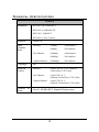
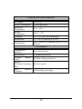
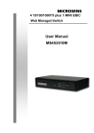
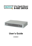
User’s Guide
DN-8007C1
TABLE
OF
C ONTENTS
ABOUT THIS GUIDE...................................................... 2
TERMS ........................................................................... 2
OVERVIEW OF THIS USER’S GUIDE .................................. 2
INTRODUCTION ............................................................ 3
GIGABIT ETHERNET TECHNOLOGY................................... 3
SWITCHING TECHNOLOGY ............................................... 4
FEATURES ..................................................................... 5
UNPACKING AND SETUP............................................. 6
UNPACKING ................................................................... 6
SETUP ........................................................................... 6
IDENTIFYING EXTERNAL COMPONENTS .................. 7
FRONT PANEL ................................................................ 7
REAR PANEL .................................................................. 7
LED INDICATORS ........................................................... 8
TECHNICAL SPECIFICATIONS .................................... 9
ABOUT THIS GUIDE
This user’s guide tells you how to install your 5-Port
1000BASE-T Gigabit Ethernet Switch, how to connect it
to your Gigabit Ethernet network.
Terms
For simplicity, this documentation uses the terms
“Switch” (first letter upper case) to refer to the 5-Port
1000BASE-T Gigabit Ethernet Switch, and “switch” (first
letter lower case) to refer to all Ethernet switches,
including the 5-Port 1000BASE-T Gigabit Ethernet
Switch.
Overview of this User’s Guide
Introduction. Describes the Switch and its features.
Unpacking and Setup. Helps you get started with the
basic installation of the Switch.
Identifying External Components. Describes the front
panel, rear panel and LED indicators of the Switch.
Technical Specifications. Lists all the technical
specifications of the Switch.
2
INTRODUCTION
This section describes the features of the 5-Port
1000BASE-T Gigabit Ethernet Switch, as well as
providing some background information about Gigabit
Ethernet and switching technology.
Gigabit Ethernet Technology
Gigabit Ethernet is an extension of IEEE 802.3 Ethernet
utilizing the same packet structure, format, and support
for CSMA/CD protocol, full duplex, flow control, and
management objects, but with a tenfold increase in
theoretical throughput over 100-Mbps Fast Ethernet and
a hundredfold increase over 10-Mbps Ethernet. Since it is
compatible with all 10-Mbps and 100-Mbps Ethernet
environments,
Gigabit
Ethernet
provides
a
straightforward upgrade without wasting a company’s
existing investment in hardware, software, and trained
personnel.
The increased speed and extra bandwidth offered by
Gigabit Ethernet is essential to coping with the network
bottlenecks that frequently develop as computers and
their busses get faster and more users use applications
that generate more traffic. Upgrading key components,
such as your backbone and servers to Gigabit Ethernet
can greatly improve network response times as well as
significantly speed up the traffic between your subnets.
Gigabit Ethernet supports video conferencing, complex
imaging, and similar data-intensive applications.
Likewise, since data transfers occur 10 times faster than
3
Fast Ethernet, servers outfitted with Gigabit Ethernet
NIC’s are able to perform 10 times the number of
operations in the same amount of time.
Switching Technology
Another key development pushing the limits of Ethernet
technology is in the field of switching technology. A
switch bridges Ethernet packets at the MAC address
level of the Ethernet protocol transmitting among
connected Ethernet or fast Ethernet LAN segments.
Switching is a cost-effective way of increasing the total
network capacity available to users on a local area
network. A switch increases capacity and decreases
network loading by making it possible for a local area
network to be divided into different segments which don’t
compete with each other for network transmission
capacity, giving a decreased load on each.
The switch acts as a high-speed selective bridge
between the individual segments. Traffic that needs to go
from one segment to another is automatically forwarded
by the switch, without interfering with any other
segments. This allows the total network capacity to be
multiplied, while still maintaining the same network
cabling and adapter cards.
Switching LAN technology is a marked improvement over
the previous generation of network bridges, which were
characterized by higher latencies. Routers have also
been used to segment local area networks, but the cost
of a router and the setup and maintenance required
make routers relatively impractical. Today’s switches are
4
an ideal solution to most kinds of local area network
congestion problems.
Features
The 5-Port 1000BASE-T Gigabit Ethernet Switch was
designed for easy installation and high performance in an
environment where traffic on the network and the number
of users increase continuously.
5 1000BASE-T Gigabit Ethernet ports
Supports Auto-Negotiation for 10/100/1000Mbps and
duplex mode
Supports Auto-MDIX for each port
Support Full/Half duplex transfer mode for 10 and
100Mbps
Support Full duplex transfer mode for 1000Mbps
Full wire speed reception and transmission
Store-and-Forward switching method
Supports 8K absolute MAC addresses
Supports 112KBytes RAM for data buffering
Extensive front-panel diagnostic LEDs
IEEE 802.3x flow control for full-duplex
Back pressure flow control for half-duplex
5
UNPACKING
AND
SETUP
This chapter provides unpacking and setup information for the
Switch.
Unpacking
Open the shipping carton of the Switch and carefully unpack its
contents. The carton should contain the following items:
One 5-Port 1000BASE-T Gigabit Ethernet Switch
Four rubber feet with adhesive backing
One external power adapter
This User’s Guide
If any item is found missing or damaged, please contact your
local reseller for replacement.
Setup
The setup of the Switch can be performed using the following
steps:
Install the Switch in a fairly cool and dry place. See
Technical Specification for the acceptable operation
temerature and humidity ranges.
Install the Switch in a site free from strong
electromagnetic source,vibration, dust,and direct sunlight.
Leave at least 10cm of space at the left and right hand
side of the Switch for ventilation.
Visually inspect the DC power jack and make sure that it
is fully secured to the power adapter.
6
IDENTIFYING EXTERNAL COMPONENTS
This chapter describes the front panel, rear panel and LED
indicators of the Switch
Front Panel
The figure below shows the front panels of the switch.
Front panel view of the Switch
LED Indicators
Comprehensive LED indicators display the conditions of the
Switch and status of the network. A description of these LED
indicators follows (see LED Indicators).
Rear Panel
The rear panel of the Switch consists of an DC power
connector. The following figure shows the rear panel of the
Switch.
Rear panel view of the Switch
DC Power Jack:
7
Power is supplied through an external AC power adapter. Check
the technical specification section for information about the AC
power input voltage.
1000BASE-T Ports:
Five Gigabit Ethernet
Negotiation interface.
ports
of
10/100/1000Mbps
Auto-
LED Indicators
The LED indicators of the Switch include Power, Link/Act,
1000Mbps and 100Mbps. The following shows the LED
indicators for the Switch along with an explanation of each
indicator.
POWER
This indicator lights green when the Switch is receiving power,
otherwise, it is off.
Link/Act
These LED indicators are lighted up when there is a secure
connection (or link) to the desired port. The LED indicators
blinking whenever there is reception or transmission (i.e.
Activity—Act) of data occurring at a port.
1000Mbps
These LED indicators are lighted up when there is a secure
connection (or link) to 1000Mbps Gigabit Ethernet device at
the desired port.
100Mbps
These LED indicators are lighted up when there is a secure
connection (or link) to 100Mbps Fast Ethernet device at the
desired port.
When the connection (or link) is 10Mbps, both of
1000Mbps and 100Mbps LED indicators are off.
8
TECHNICAL SPECIFICATIONS
General
Standards:
IEEE 802.3ab 1000BASE-T
IEEE 802.3u 100BASE-TX
IEEE 802.3 10BASE-T
IEEE 802.3x Flow Control
Protocol:
CSMA/CD
Data
Transfer
Rate:
Ethernet:
Fast Ethernet:
Gigabit Ethernet:
10Mbps
(Half-duplex)
20Mbps
(Full-duplex)
100Mbps
(Half-duplex)
200Mbps
(Full-duplex)
2000Mbps
(Full-duplex)
Topology:
Star
Network
Cables:
Ethernet:
2-pair UTP Cat. 3,4,5, Unshield
Twisted Pair (UTP )Cable
Fast Ethernet:
2-pair UTP Cat. 5,
Unshield Twisted Pair (UTP )Cable
Gigabit Ethernet:
4-pair UTP Cat. 5,
Unshield Twisted Pair (UTP )Cable
Number
Ports:
of
Five(5) 1000BASE-T Gigabit Ethernet ports
9
Physical and Environmental
DC inputs:
Power Consumption:
Operating
Temperature:
Storage
Temperature:
Humidity:
Dimensions:
Certification:
7.5V 1A
5 watts maximum
0 °C ~ 40°C
-10°C ~ 70°C
5% ~ 95% RH, non-condensing
171 x 98 x 29 mm (W x H x D)
FCC Class B, CE Marking Class B, VCCI
Class B
Performance
Transmission
Method:
RAM Buffer:
Filtering
Address
Table:
Packet
Filtering/Forwarding
Rate:
MAC
Address
Learning:
Store-and-forward
112KBytes per device
8K MAC address per device
Full wire speed
Self-learning, auto-aging
10
Note:
In the event of incorrect installation and improper use in a
residential area, the device may cause disruptions in radio
devices and other electronic devices. Proper use means that
the device is operated with shielded connector cables as far as
possible, for network products also with shielded cables of
category 5e and higher. The device was tested and lies within
the limits for computer accessories of class A according to the
requirements of EN 55022.
Warning !
This is a class A device. This device can cause radio
interference in residential areas; in this case, the operator may
be required to perform and bear the costs for appropriate
measures.
Conformity Declaration:
The device fulfils the EMC requirements of EN 55022 class A
for ITE and EN 55024. Devices with external or built-in power
supply also fulfil the requirements of EN 61000-3-2 and EN
61000-3-3. The basic protection requirements of the “EMC
Directive” 89/336/EEC are therefore fulfilled. The CE conformity
has been certified. The corresponding declarations are available
from the manufacturer.
Trademarks:
All company, brand and product names used in these
instructions are trademarks or registered marks of the
corresponding companies.
11