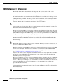
1
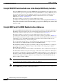
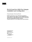
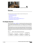
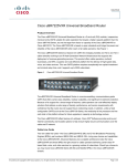
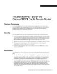
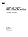
C H A P T E R
1
Overview
This chapter describes the PA-MC-T3 port adapter and contains the following sections:
•
Port Adapter Overview, page 1-1
•
Multichannel T3 Overview, page 1-2
•
Features, page 1-3
•
Interface Specifications, page 1-3
•
LEDs, page 1-4
•
Cables, Connectors, and Pinouts, page 1-5
•
Port Adapter Slot Locations on the Supported Platforms, page 1-7
•
Identifying Interface Addresses, page 1-17
Port Adapter Overview
The PA-MC-T3 is a single-width single-port, port adapter that provides one T3 interface connection
using BNC connectors. (See Figure 1-1.) The interface can provide up to 28 T1 lines (a single T3 group).
Each T1 line is presented to the system as a serial interface that can be configured individually.
Figure 1-1
PA-MC-T3 —Faceplate View
PA-MC-T3 Port Adapter Installation and Configuration
OL-2695-05
1-1
Chapter 1
Overview
Multichannel T3 Overview
Multichannel T3 Overview
The PA-MC-T3 T3 link is channelized into 28 independent T1 data lines. Each T1 line can be
unchannelized or channelized for serial transmission of data.
Each of the T1 lines can use the whole T1 bandwidth, a portion of the T1 bandwidth, or the T1 bandwidth
in channelized form for data transmission. Usable bandwidths for each T1 line are n x 56 kbps or n x 64
kbps, where n is a number representing time slots 1 to 24. Channelized T1 allows up to 24 time slots
(56 kbps/64 kbps) per T1 line. The unused portion of the T1 bandwidth, when not running at full T 1
speeds, cannot be used and is filled with idle channel data. Aggregation of multiple T1 lines is not
supported. The PA-MC-T3 can support a maximum of 128 logical channels.
Note
T1 lines on the PA-MC-T3 are numbered 1 to 28 instead of the more traditional zero-based scheme (0 to
27) used with other Cisco products. This is to ensure consistency with telco numbering schemes for T1
lines within channelized (multi-channel) T3 equipment.
The T3 section of the PA-MC-T3 supports the maintenance data link channel (when using c-bit parity)
as well as payload and network loopbacks. The T1 section of the PA-MC-T3 supports facilities data link
(FDL) in Extended Superframe (ESF) framing, as well as various loopbacks. Bit error rate (BER) testing
is supported on each of the T1 lines. Testing is typically done over an unframed T1 signal.
The PA-MC-T3 supports Cisco High-Level Data Link Control (HDLC), Frame Relay, PPP, and SMDS
Data Exchange Interface (DXI) encapsulations over each T1 link. For Switched Multimegabit Data
Service (SMDS) only, DXI is sent on the T1 line, so it needs to connect to an SMDS switch that has
direct DXI input.
Note
The PA-MC-T3 does not support the aggregation of multiple T1 lines (called inverse multiplexing, or
bonding) for higher bandwidth data rates.
The physical T3 link on the PA-MC-T3 consists of two female BNC connectors, one for receive (RX)
and one for transmit (TX). You must use 75-ohm RG-59 coaxial interface cables with male BNC
connectors to connect the PA-MC-T3 interface with external T3 equipment. (For cable information, refer
to the “Cables, Connectors, and Pinouts” section on page 1-5.)
Any of the 28 T1 lines can be configured as channelized T1 lines. You can group the time slots in these
T1 lines into several individual logical channel groups, each of which carries data with different
data-link layer protocol encapsulations.
Each logical channel group can be composed of individual 56-kbps or 64-kbps time slots, or individual
time slots plus ranges of time slots; for example, a channel group might be composed of time slots 1, 9,
and 12–14. Each logical channel group can contain from 1 to 24 time slots maximum; the same time slot
cannot be used in more than one logical channel group. Any unused time slots are filled with
programmable idle-channel data.
Each T1 line contains onboard T1 bit error rate test (BERT) circuitry. With this, the port adapter software
can send and detect programmable patterns, and you can run a BERT on any T1 line or all of the 28 T1
lines simultaneously.
Note
Onboard T3 BER testing is not supported.
PA-MC-T3 Port Adapter Installation and Configuration
1-2
OL-2695-05
Chapter 1
Overview
Features
Features
The PA-MC-T3 contains the following features:
•
Transmits and receives data bidirectionally at the T3 rate of 44.736 Mbps (digital signal carried on
a T3 line, digital signal level 3 [DS3]).
•
The T3 connection, provided by way of two female BNC connections for transmit (TX) and receive
(RX), requires RG-59 coaxial cable that has an impedance of 75 ohms.
•
Supports RFC 1406 and RFC 1407 (CISCO-RFC-1407-CAPABILITY.my). For RFC 1406, Cisco
supports all tables except the Frac table. For RFC 1407, Cisco supports all tables except the FarEnd
tables. (For information on accessing Cisco MIB files, refer to the Cisco Management Information
Base (MIB) User Quick Reference
•
PA-MC-T3 microcode is loaded into and operates from DRAM (or SDRAM) configuration and is
determined by the VIP model on which the PA-MC-T3 is installed.
•
On the Catalyst RSM/VIP2, PA-MC-T3 microcode is loaded into and operates from DRAM on the
Catalyst RSM/VIP2-40.
Interface Specifications
The PA-MC-T3 T3 port is designed to receive and transmit at the DSX-3 level while driving and
receiving from a 75-ohm coaxial cable (ATT 728A type coax). The T3 port connects directly to any
equipment with DSX-3-level BNC connectors.
Table 1-1 lists the specifications the T3 front end is designed to meet.
Table 1-1
Specifications for the T3 Front End
Parameter
Specification
Line rate
44.736 Mbps (±20 ppm)
Line code
B3ZS (bipolar with three-zero substitution)
Impedance
75 ohms
Pulse shape
ANSI T1.102, pulse amplitude is between 0.36 and 0.85 volts (V) peak
Input signal
DSX-3 (9.7 dB to –11.8 dB)
Output signal
DSX-3, able to drive 450 feet (135 meters) of 75-ohm coaxial cable (728A or
equivalent) and meet pulse shape template at the line side
PA-MC-T3 Port Adapter Installation and Configuration
OL-2695-05
1-3
Chapter 1
Overview
LEDs
LEDs
The PA-MC-T3 has one row of six status LEDs and one ENABLED LED. (See Figure 1-2.)
Figure 1-2
PA-MC-T3 LEDs
Table 1-2 lists port LED colors and indications.
Table 1-2
PA-MC-T3 LEDs
LED Label
Color
State
Meaning
ENABLED
Green
On
Port adapter is enabled for operation.
ALARM
Yellow
On
An alarm condition1 is received on any configured T1 line or the
T3 link.
Blinking A port adapter boot failure has occurred.2
LOOP
Yellow
On
A T1 line or the T3 link is in a loopback state and is not enabled
for normal data traffic.
LOS
Yellow
On
A loss of the received signal on the T3 link is detected by the line
interface unit (LIU) on the port adapter.
OOF
Yellow
On
A DS3 out-of-frame condition.
AIS
Yellow
On
An alarm indication signal is received on the T3 link.
FERF
Yellow
On
A far-end receive failure signal is detected by the receiver.3
1. Alarms include: T1 loss of frame (LOF), T1 alarm indication signal (AIS), T1 yellow alarm indication, T3 loss of signal
(LOS), T3 AIS, and a T3 far-end receive failure (FERF) yellow alarm.
2. This LED blinks momentarily during port adapter initialization.
3. When the OOF LED is on, the FERF LED is latched to its state prior to the out-of-frame condition; that is, it reflects the last
known state of the far-end receiver. When the OOF LED is off, the FERF LED reflects the live state of the far-end receiver.
After system initialization, the ENABLED LED goes on to indicate that the port adapter is enabled for
operation.
The following conditions must be met before the PA-MC-T3 is enabled:
•
The port adapter is correctly connected to and receiving power from one of the following:
– Catalyst RSM/VIP2 motherboard
– Catalyst 6000 family FlexWAN module
– VIP
•
A valid system software image for the port adapter has been downloaded successfully.
PA-MC-T3 Port Adapter Installation and Configuration
1-4
OL-2695-05
Chapter 1
Overview
Cables, Connectors, and Pinouts
•
The system bus recognizes one of the following:
– PA-MC-T3
– Catalyst RSM/VIP2 with a PA-MC-T3
– Catalyst 6000 family FlexWAN module with a PA-MC-T3
– VIP with a PA-MC-T3
If any of the above conditions is not met, or if the initialization fails for other reasons, the enabled LED
does not go on.
Note
In addition to the interface status information provided by the LEDs, you can also retrieve detailed
interface status information either through the router’s console port or through Telnet or Simple Network
Management Protocol (SNMP).
Cables, Connectors, and Pinouts
The interface connectors on the PA-MC-T3 are RG-59 coaxial BNC types, with one connector and cable
for transmit (TX) and one for receive (RX). The BNC connectors are transformer-coupled to the
PA-MC-T3 line interface unit (LIU), which is the analog physical interface on the PA-MC-T3.
The pinout and signal descriptions for the BNC connectors on the PA-MC-T3 are as follows:
Caution
•
Transmit (TX)—Transmitted signals appear on the center contact, and the outer shield is ground for
the 75-ohm RG-59 coaxial cable you attach to the TX BNC connector.
•
Receive (RX)—Received signals appear on the center contact, and the outer shield is ground for the
75-ohm RG-59 coaxial cable you attach to the RX BNC connector.
To prevent problems, you must check your 75-ohm RG-59 coaxial cable specifications when long cable
lengths are required to connect the PA-MC-T3 to your external DS3 (T3) equipment.
You must install a ferrite sleeve (also called a common-mode choke) on each 75-ohm coaxial cable to
reduce the effects of electromagnetic interference (EMI). (Cisco Systems supplies two ferrite sleeves
with your PA-MC-T3, one for each of the two 75-ohm coaxial cables.)
Note
You must attach the ferrite sleeve on the end of each coaxial cable, nearest the PA-MC-T3, as close to
the BNC connector as possible. (See Figure 1-3.)
Caution
The ferrite sleeve prevents electromagnetic interference (EMI) from affecting the T3-equipped system
and is a required component for proper system operation.
PA-MC-T3 Port Adapter Installation and Configuration
OL-2695-05
1-5
Chapter 1
Overview
Cables, Connectors, and Pinouts
Figure 1-3
Attaching the Ferrite Sleeve Around a Coaxial Cable
Figure 1-4 shows the typical 75-ohm RG-59 coaxial cable pair that you supply and should use with the
PA-MC-T3. Use only this type of coaxial cable pair for your PA-MC-T3 connections. Use one 75-ohm
coaxial cable for each PA-MC-T3 connection: RX and TX.
We strongly recommend that you fasten together your transmit and receive cables along their entire
length, as shown in Figure 1-4, which reduces the effects of EMI. You can use standard heat-activated
shrink tubing or cable ties for this purpose.
Figure 1-4
75-Ohm RG-59 Coaxial Cable Pair with Ferrite Sleeves Attached
You can also order from Cisco Systems a 75-ohm coaxial cable pair with ferrite beads attached (Cisco
Product Number CAB-ATM-DS3/E3). (See Figure 1-5.) This 75-ohm coaxial cable pair is not available
from outside commercial cable vendors.
Figure 1-5
CAB-ATM-DS3/E3 Cable—75-Ohm RG-59 Coaxial Cable with BNC Connectors
PA-MC-T3 Port Adapter Installation and Configuration
1-6
OL-2695-05
Chapter 1
Overview
Port Adapter Slot Locations on the Supported Platforms
Port Adapter Slot Locations on the Supported Platforms
This section discusses port adapter slot locations on the supported platforms. The illustrations that
follow summarize slot location conventions on each platform:
•
Catalyst RSM/VIP2 Slot Numbering, page 1-7
•
Catalyst 6000 Family FlexWAN Module Slot Numbering, page 1-9
•
Cisco 7200 Series Routers and Cisco 7200 VXR Routers Slot Numbering, page 1-10
•
Cisco uBR7200 Series Router Slot Numbering, page 1-11
•
Cisco 7201 Router Slot Numbering, page 1-13
•
Cisco 7301 Router Slot Numbering, page 1-13
•
Cisco 7304 PCI Port Adapter Carrier Card Slot Numbering, page 1-14
•
Cisco 7401ASR Router Slot Numbering, page 1-15
•
Cisco 7000 Series Routers and Cisco 7500 Series Routers VIP Slot Numbering, page 1-15
Catalyst RSM/VIP2 Slot Numbering
The Catalyst RSM/VIP2 can be installed in any slot in a Catalyst 5000 family switch except the top slots,
which contain the supervisor engines. The Catalyst RSM/VIP2 does not use interface processor slot
numbering; therefore, the slots in which it is installed are not numbered. A port adapter can be installed
into either port adapter slot 0 or slot 1 on a Catalyst RSM/VIP2. Figure 1-6 shows a Catalyst 5000 family
switch with two port adapters installed in a Catalyst RSM/VIP2.
Figure 1-6
Catalyst 5000 Family Switch with Port Adapters Installed on Catalyst RSM/VIP2
PA-MC-T3 Port Adapter Installation and Configuration
OL-2695-05
1-7
Chapter 1
Overview
Port Adapter Slot Locations on the Supported Platforms
Figure 1-7 shows two PA-MC-T3s installed in port adapter slot 0 and slot 1 on a Catalyst RSM/VIP2-40.
Figure 1-7
Catalyst RSM/VIP2-40 with Two PA-MC-T3s
PA-MC-T3 Port Adapter Installation and Configuration
1-8
OL-2695-05
Chapter 1
Overview
Port Adapter Slot Locations on the Supported Platforms
Catalyst 6000 Family FlexWAN Module Slot Numbering
The Catalyst 6000 family FlexWAN module can be installed in any slot in a Catalyst 6000 family switch
except slot 1, which is reserved for the supervisor engine. A port adapter can be installed into either port
adapter bay 0 or bay 1 on a FlexWAN module. Figure 1-8 shows a Catalyst 6000 family switch with two
blank port adapters installed in a FlexWAN module.
Note
Slot 1 is reserved for the supervisor engine. If a redundant supervisor engine is used, it would go in
slot 2; otherwise, slot 2 can be used for other modules.
Figure 1-8
Catalyst 6000 Family Switch with Port Adapters Installed on FlexWAN Module
PA-MC-T3 Port Adapter Installation and Configuration
OL-2695-05
1-9
Chapter 1
Overview
Port Adapter Slot Locations on the Supported Platforms
Cisco 7200 Series Routers and Cisco 7200 VXR Routers Slot Numbering
Cisco 7202 routers have two port adapter slots. The slots are numbered from left to right. You can place
a port adapter in either of the slots (slot 1 or slot 2). The Cisco 7202 router is not shown.
Cisco 7204 routers and Cisco 7204VXR routers have four slots for port adapters, and one slot for an
input/output (I/O) controller. The slots are numbered from the lower left to the upper right, beginning
with slot 1 and continuing through slot 4. You can place a port adapter in any of the slots (slot 1 through
slot 4). Slot 0 is always reserved for the I/O controller. The Cisco 7204 router and Cisco 7204VXR are
not shown.
Cisco 7206 routers and Cisco 7206VXR routers (including the Cisco 7206 and Cisco 7206VXR routers
as router shelves in a Cisco AS5800 Universal Access Server) have six slots for port adapters, and one
slot for an input/output (I/O) controller. The slots are numbered from the lower left to the upper right,
beginning with slot 1 and continuing through slot 6. You can place a port adapter in any of the six slots
(slot 1 through slot 6). Slot 0 is always reserved for the I/O controller.
Figure 1-9 shows the slot numbering on a Cisco 7206 router.
Figure 1-9
Port Adapter Slots in the Cisco 7206 Router
PA-MC-T3 Port Adapter Installation and Configuration
1-10
OL-2695-05
Chapter 1
Overview
Port Adapter Slot Locations on the Supported Platforms
Figure 1-10 shows a PA-MC-T3 in port adapter slot 3 of the Cisco 7206 router.
Figure 1-10
Cisco 7206 with a PA-MC-T3
The Cisco 7206VXR router is not shown.
Cisco uBR7200 Series Router Slot Numbering
The Cisco uBR7223 router has one port adapter slot (slot 1). Slot 0 is always reserved for the I/O
controller—if present. The Cisco uBR7223 router is not shown.
The Cisco uBR7246 router and Cisco uBR7246VXR router have two port adapter slots (slot1 and slot
2). Slot 0 is always reserved for the I/O controller—if present.
PA-MC-T3 Port Adapter Installation and Configuration
OL-2695-05
1-11
Chapter 1
Overview
Port Adapter Slot Locations on the Supported Platforms
Figure 1-11 shows the slot numbering of port adapters on a Cisco uBR7246 router or Cisco
uBR7246VXR router.
Figure 1-11
Port Adapter Slots in the Cisco uBR7246 and Cisco uBR7246VXR Routers
Figure 1-12 shows a PA-MC-T3 installed in port adapter slot 2 of a Cisco uBR7246 router.
Figure 1-12
Cisco uBR7246 With a PA-MC-T3
PA-MC-T3 Port Adapter Installation and Configuration
1-12
OL-2695-05
Chapter 1
Overview
Port Adapter Slot Locations on the Supported Platforms
Cisco 7201 Router Slot Numbering
Figure 1-13 shows the front view of a Cisco 7201 router with a port adapter installed. There is only one
port adapter slot (slot 1) in a Cisco 7201 router.
Figure 1-13
Port Adapter Slot in the Cisco 7201 Router
Cisco 7301 Router Slot Numbering
Figure 1-14 shows the front view of a Cisco 7301 router with a port adapter installed. There is only one
port adapter slot (slot 1) in a Cisco 7301 router.
Figure 1-14
Port Adapter Slot in the Cisco 7301 Router
PA-MC-T3 Port Adapter Installation and Configuration
OL-2695-05
1-13
Chapter 1
Overview
Port Adapter Slot Locations on the Supported Platforms
Cisco 7304 PCI Port Adapter Carrier Card Slot Numbering
The Cisco 7304 PCI port adapter carrier card installs into Cisco 7304 router module slots 2 through 5.
Figure 1-15 shows the module slot numbering on a Cisco 7304 router. The port adapter slot number is
the same as the module slot number. Slot 0 and slot 1 are reserved for the NPE module or NSE module.
Figure 1-16 shows a Cisco 7304 PCI port adapter carrier card with a port adapter installed. The Cisco
7304 PCI port adapter carrier card accepts one single-width port adapter.
Figure 1-15
Module Slots on the Cisco 7304 Router
Figure 1-16
Cisco 7304 PCI Port Adapter Carrier Card—Port Adapter Installed
PA-MC-T3 Port Adapter Installation and Configuration
1-14
OL-2695-05
Chapter 1
Overview
Port Adapter Slot Locations on the Supported Platforms
Cisco 7401ASR Router Slot Numbering
Figure 1-17 shows the front view of a Cisco 7401ASR router with a port adapter installed. There is only
one port adapter slot (slot 1) in a Cisco 7401ASR router.
Figure 1-17
Port Adapter Slot in Cisco 7401ASR Router
Cisco 7000 Series Routers and Cisco 7500 Series Routers VIP Slot Numbering
The PA-MC-T3 is supported on theVIP2 and VIP4 versatile interface processors used in Cisco 7000
series and Cisco 7500 series routers. In the Cisco 7010 router and Cisco 7505 router, the VIP
motherboard is installed horizontally in the VIP slot. In the Cisco 7507 router and Cisco 7513 router, the
VIP motherboard is installed vertically in the VIP slot. The port adapter can be installed in either bay
(port adapter slot 0 or 1) on the VIP. The bays are numbered from left to right on the VIP.
Figure 1-18 shows the slot numbering on a VIP2.
Figure 1-18
VIP2 Slot Locations
PA-MC-T3 Port Adapter Installation and Configuration
OL-2695-05
1-15
Chapter 1
Overview
Port Adapter Slot Locations on the Supported Platforms
Figure 1-19 shows the slot numbering on a VIP4.
Figure 1-19
VIP4 Slot Locations
Figure 1-20 shows two PA-MC-T3 port adapters in slot 0 and slot 1 of a VIP2-40.
Figure 1-20
Two PA-MC-T3s in Port Adapter Slot 0 and Slot 1 of a VIP2-40
PA-MC-T3 Port Adapter Installation and Configuration
1-16
OL-2695-05
Chapter 1
Overview
Identifying Interface Addresses
Cisco 7010 routers have three slots for port adapters, and two slots for Route Switch Processors (RSPs).
The slots are numbered from bottom to top. You can place the port adapter in any of the VIP interface
slots (slot 0 through 2). Slots 3 and 4 are always reserved for RSPs. The Cisco 7010 router is not shown.
Cisco 7505 routers have four slots for port adapters, and one slot for an RSP. The slots are numbered
from bottom to top. You can place the port adapter in any of the VIP interface slots (slot 0 through 3).
One slot is always reserved for the RSP. The Cisco 7505 router is not shown.
Cisco 7507 routers have five slots for port adapters, and two slots for RSPs. The slots are numbered from
left to right. You can place the port adapter in any of the VIP interface slots (slot 0, 1, 4, 5, or 6). Slots
2 and 3 are always reserved for RSPs. The Cisco 7507 router is not shown.
Cisco 7513 routers have eleven slots for port adapters, and two slots for RSPs. The slots are numbered
from left to right. You can place the port adapter in any of the VIP interface slots (slots 0 through 5, or
slots 9 through 12). Slots 6 and 7 are always reserved for RSPs. The Cisco 7513 router is not shown.
Identifying Interface Addresses
This section describes how to identify interface addresses for the PA-MC-T3 in supported platforms.
Interface addresses specify the actual physical location of each interface on a router or switch.
Note that PA-MC-T3 interface addresses always end with t1-line-number:channel-group-number where:
•
t1-line-number identifies the T1 line number on the PA-MC-T3 and is a number from 1 through 28.
•
channel-group-number identifies the logical channel group on the T1 line and is a number from 0
through 23.
Interfaces on a PA-MC-T3 installed in a router maintain the same address regardless of whether other
port adapters are installed or removed. However, when you move a port adapter to a different slot, the
first number in the interface address changes to reflect the new port adapter slot number.
Interfaces on a PA-MC-T3 installed in a VIP or FlexWAN module maintain the same address regardless
of whether other interface processors or modules are installed or removed. However, when you move a
VIP or FlexWAN module to a different slot, the interface processor or module slot number changes to
reflect the new interface processor or module slot.
Note
The Cisco IOS software recognizes a configured logical channel group as a serial interface; therefore,
you can use all configuration commands that are available for serial interfaces with configured logical
channel groups. You can configure a logical channel group to carry data traffic using the following
encapsulation methods: PPP, HDLC, SMDS, and Frame Relay. Set the encapsulation method you want
using the serial interface configuration commands. For configured logical channel groups, you can use
all command switches that apply to a serial interface (including optimum switching).
Note
Interface ports are numbered from left to right starting with 0.
PA-MC-T3 Port Adapter Installation and Configuration
OL-2695-05
1-17
Chapter 1
Overview
Identifying Interface Addresses
The following subsections describe the interface address formats for the supported platforms:
•
Catalyst RSM/VIP2 Interface Addresses in the Catalyst 5000 Family Switches, page 1-20
•
Catalyst 6000 Family FlexWAN Module Interface Addresses, page 1-20
•
Cisco 7200 Series Routers and Cisco 7200 VXR Routers Interface Addresses, page 1-21
•
Cisco uBR7200 Series Routers Interface Addresses, page 1-21
•
Cisco 7201 Router Interface Addresses, page 1-21
•
Cisco 7301 Router Interface Addresses, page 1-21
•
Cisco 7304 PCI Port Adapter Carrier Card Interface Addresses, page 1-22
•
Cisco 7401ASR Router Interface Addresses, page 1-22
•
Cisco 7000 Series Routers and Cisco 7500 Series Routers VIP Interface Addresses, page 1-22
Table 1-3 summarizes the interface address formats for the supported platforms.
Table 1-3
Identifying Interface Addresses
Platform
Interface Address Format
Numbers
Syntax
Catalyst RSM/VIP in
Catalyst 5000 family
switches
Port-adapter-slot-number/interface-port-number/
t1-line-number:channel-group-number
Port adapter slot— 0 or 1
0/0/1:0
Interface port—0
T1 line number—1 through 28
Logical channel group on the T1
line—0 through 23
Catalyst 6000 family
FlexWAN module in
Catalyst 6000 family
switches
Module-slot-number/port-adapter-bay-number/
interface-port-number/t1-line-number:channelgroup-number
Module slot—21 through 13
(depends on the number of slots
in the switch)
3/0/0/1:0
Port adapter bay—0 or 1
Interface port—0
T1 line number—1 though 28
Logical channel group on the T1
line—0 through 23
Cisco 7200 series
routers and Cisco 7200
VXR routers
Port-adapter-slot-number/interface-port-number/
t1-line-number:channel-group-number
Port adapter slot—1 through 6
(depends on the number of slots
in the router)2
1/0/1:0
Interface port—0
T1 line number—1 through 28
Logical channel group on the T1
line—0 through 23
Cisco 7201 router
Port-adapter-slot-number/interface-port-number/
t1-line-number:channel-group-number
Port adapter slot—Always 1
1/0/1:0
Interface port—0
T1 line number—1 through 28
Logical channel group on the T1
line—0 through 23
PA-MC-T3 Port Adapter Installation and Configuration
1-18
OL-2695-05
Chapter 1
Overview
Identifying Interface Addresses
Table 1-3
Identifying Interface Addresses (continued)
Platform
Interface Address Format
Cisco uBR7223 router
Numbers
Port-adapter-slot-number/interface-port-number/
t1-line-number:channel-group-number
Port adapter slot—Always 1
Syntax
2
1/0/1:0
Interface port—0
T1 line number—1 through 28
Logical channel group on the T1
line—0 through 23
Cisco uBR7246 router
Port-adapter-slot-number/interface-port-number
t1-line-number:channel-group-number
Port adapter slot—1 or 22
1/0/1:0
Interface port—0
T1 line number—1 through 28
Logical channel group on the T1
line—0 through 23
Cisco 7301 router
Port-adapter-slot-number/interface-port-number/
t1-line-number:channel-group-number
Port adapter slot—Always 1
1/0/1:0
Interface port—0
T1 line number—1 through 28
Logical channel group on the T1
line—0 through 23
Cisco 7304 PCI port
adapter carrier card in
Cisco 7304 router
Module-slot-number/interface-port-number/
t1-line-number:channel-group-number
Module slot— 2 through 5
3/0/1:0
Interface port—0
T1 line number—1 through 28
Logical channel group on the T1
line—0 through 23
Cisco 7401ASR router
Port-adapter-slot-number/interface-port-number/
t1-line-number:channel-group-number
Port adapter slot—Always 1
1/0/1:0
Interface port—0
T1 line number—1 through 28
Logical channel group on the T1
line—0 through 23
VIP in Cisco 7000
Interface-processor-slot-number/port-adapter-slot Interface processor slot—0
series routers or
-number/interface-port-number/t1-line-number:
through 12 (depends on the
Cisco 7500 series router channel-group-number
number of slots in the router)
3/1/0/1:0
Port adapter slot— 0 or 1
Interface port— 0
T1 line number—1 through 28
Logical channel group on the T1
line—0 through 23
1. Slot 1 is reserved for the supervisor engine. If a redundant supervisor engine is used, it must go in slot 2; otherwise, slot 2 can be used for other modules.
2. Port adapter slot 0 is reserved for the Fast Ethernet port on the I/O controller (if present).
PA-MC-T3 Port Adapter Installation and Configuration
OL-2695-05
1-19
Chapter 1
Overview
Identifying Interface Addresses
Catalyst RSM/VIP2 Interface Addresses in the Catalyst 5000 Family Switches
In Catalyst 5000 family switches, the Catalyst RSM/VIP2 can be installed in any slot except the top slots,
which contain the supervisor engine modules. The Catalyst RSM/VIP2 in a Catalyst 5000 family switch
does not use interface processor slot numbering; therefore, the slots in which it is installed are not
numbered. A port adapter can be installed into either port adapter slot 0 or slot 1 on a Catalyst
RSM/VIP2. See Figure 1-6 and Figure 1-7.
The interface address is composed of a four-part number in the format
port-adapter-slot number/interface-port number/t1-line-number:channel-group-number. See Table 1-3.
For example, if a PA-MC-T3 is installed in port adapter slot 1 of a Catalyst RSM/VIP2 in a Catalyst 5000
family switch, the interface address would be 1/0/1/0 (port adapter slot 1, interface port 0, T1 line 1, and
channel group 0).
Catalyst 6000 Family FlexWAN Module Interface Addresses
The Catalyst 6000 family FlexWAN module can be installed in module slots 2 through 9 (depending on
the number of slots in the router). Slot 1 is reserved for the supervisor engine. A port adapter can be
installed into either port adapter bay 0 or bay 1 on a FlexWAN module. See Figure 1-8.
The interface address is composed of a five-part number in the format module-number/
port-adapter-bay-number/interface-port-number/t1-line-number:channel-group-number. See Table 1-3.
The first number identifies the module slot of the chassis in which the FlexWAN module is installed (slot
2 through slot 3, 6, or 9 depending on the number of slots in the chassis). These module slots are
generally numbered from top to bottom, starting with 1.
The second number identifies the bay of the FlexWAN module in which the port adapter is installed
(0 or 1). The bays are numbered from left to right on the FlexWAN module.
The third number identifies the physical port number on the port adapter. The PA-T3+ is a single-port
port adapter, therefore the port number is always 0. The PA-MC-T3 is a single-port port adapter,
therefore the port is always 0.
The fourth number identifies the T1 line number on the PA-MC-T3 and is a number from 1 through 28.
The fifth number identifies the logical channel group on the T1 line and is a number from 0 through 23.
For example, if a PA-MC-T3 is installed in the FlexWAN module in module slot 3, port adapter bay 0,
the interface address would be 3/0/0/1:0 (module slot 3, port adapter bay 0, interface port 0, T1 line 1,
logical channel group 0). If the port adapter was in port adapter bay 1 on the FlexWAN module, the
interface address would be 3/1/0/1:0.
Note
If you remove the FlexWAN module with the PA-MC-T3 from module slot 3 and install it in module slot
6, port adapter bay 0, the interface address would become 6/0/0/1:0.
Note
The FlexWAN module physical port address begins with slot 0, which differs from the conventional
Catalyst 6000 family port address, which begins with slot 1.
PA-MC-T3 Port Adapter Installation and Configuration
1-20
OL-2695-05
Chapter 1
Overview
Identifying Interface Addresses
Cisco 7200 Series Routers and Cisco 7200 VXR Routers Interface Addresses
In Cisco 7200 series routers and Cisco 7200 VXR routers, port adapter slots are numbered from the
lower left to the upper right, beginning with slot 1 and continuing through slot 2 for the Cisco 7202,
slot 4 for the Cisco 7204 and Cisco 7204VXR, and slot 6 for the Cisco 7206 and Cisco 7206VXR. Port
adapters can be installed in any available port adapter slot from 1 through 6 (depending on the number
of slots in the router). (Slot 0 is reserved for the I/O controller.) See Figure 1-9 and Figure 1-10.
The interface address is composed of a four-part number in the format
port-adapter-slot-number/interface-port-number/t1-line-number: channel-group-number. See
Table 1-3. For example, if a PA-MC-T3 is installed in slot 1of a Cisco 7200 series router, the interface
address would be 1/0/1:0 (port adapter slot 1, interface port 0, T1 line 1, and logical channel group 0).
If a PA-MC-T3 were installed in slot 4, the interface address would be 4/0/1:0.
Cisco uBR7200 Series Routers Interface Addresses
In the Cisco uBR7223 router, only one slot accepts port adapters and it is numbered slot 1.
In the Cisco uBR7246 router and Cisco uBR7246VXR router, port adapters can be installed in two port
adapter slots (slot1 and slot 2). Slot 0 is always reserved for the I/O controller—if present. See
Figure 1-11 and Figure 1-12.
The interface address is composed of a four-part number in the format
port-adapter-slot-number/interface-port-number/t1-line-number: channel-group-number. See
Table 1-3. For example, if a PA-MC-T3 is installed in slot 1of a Cisco uBR7223 router, the interface
address would be 1/0/1/0 (port adapter slot 1 interface port 0, T1 line 1, and channel group 0). If the
PA-MC-T3 were installed in slot 2 of a Cisco uBR7246 router, the interface address would be 2/0/1/0
(port adapter slot 2, interface port 0, T1 line 1 and channel group 0).
Cisco 7201 Router Interface Addresses
In the Cisco 7201 router, only one slot accepts port adapters and it is numbered as slot 1. See
Figure 1-13.
The interface address is composed of a four-part number in the format
port-adapter-slot-number/interface-port-number/t1-line-number:channel-group number. See Table 1-3.
For example, if a PA-MC-T3 is installed in a Cisco 7201 router, the interface address would be 1/0/1/0
(port adapter slot 1 interface port 0, T1 line 1, and channel group 0).
Cisco 7301 Router Interface Addresses
In the Cisco 7301 router, only one slot accepts port adapters and it is numbered as slot 1. See
Figure 1-14.
The interface address is composed of a four-part number in the format
port-adapter-slot-number/interface-port-number/t1-line-number:channel-group number. See Table 1-3.
For example, if a PA-MC-T3 is installed in a Cisco 7301 router, the interface address would be 1/0/1/0
(port adapter slot 1 interface port 0, T1 line 1, and channel group 0).
PA-MC-T3 Port Adapter Installation and Configuration
OL-2695-05
1-21
Chapter 1
Overview
Identifying Interface Addresses
Cisco 7304 PCI Port Adapter Carrier Card Interface Addresses
In the Cisco 7304 router, port adapters are installed in a Cisco 7304 PCI port adapter carrier card, which
installs in Cisco 7304 router module slots 2 through 5. The port adapter slot number is the same as the
module slot number. SeeFigure 1-15 and Figure 1-16.
The interface address is composed of a four-part number in the format
port-adapter-slot-number/interface-port-number/t1-line-number:channel-group number. See Table 1-3.
For example, if a PA-MC-T3 is installed in the Cisco 7304 PCI port adapter carrier card in Cisco 7304
router module slot 3, the interface address would be 3/0/1/0 (port adapter slot 3 interface port 0, T1 line
1, and channel group 0).
Cisco 7401ASR Router Interface Addresses
In the Cisco 7401ASR router, only one slot accepts port adapters and it is numbered as slot 1. See
Figure 1-17.
The interface address is composed of a four-part number in the format
port-adapter-slot-number/interface-port-number/t1-line-number:channel-group number. See Table 1-3.
For example, if a PA-MC-T3 is installed in a Cisco 7401ASR router, the interface address would be
1/0/1/0 (port adapter slot 1 interface port 0, T1 line 1, and channel group 0).
Cisco 7000 Series Routers and Cisco 7500 Series Routers VIP Interface
Addresses
In Cisco 7000 series routers and Cisco 7500 series routers, port adapters are installed on a versatile
interface processor (VIP), which installs in interface processor slots 0 through 12 (depending on the
number of slots in the router). The port adapter can be installed in either bay (port adapter slot 0 or 1)
on the VIP. See Figure 1-18, Figure 1-19, and Figure 1-20.
The interface address for the VIP is composed of a five-part number in the format
interface-processor-slot-number/port-adapter-slot-number/interface-portnumber/t1-line-number:channel-group-number. See Table 1-3.
The first number identifies the slot in which the VIP is installed (slot 0 through 12, depending on the
number of slots in the router).
The second number identifies the bay (port adapter slot) on the VIP in which the port adapter is installed
(0 or 1). The bays are numbered from left to right on the VIP.
The third number identifies the physical port number (interface port number) on the port adapter. The
port numbers always begin at 0 and are numbered from left to right. The number of additional ports
depends on the number of ports on the port adapter. The PA-MC-T3 is a single-port port adapter,
therefore the port is always 0.
The fourth number identifies the T1 line number on the PA-MC-T3 and is a number from 1 through 28.
The fifth number identifies the logical channel group on the T1 line and is a number from 0 through 23.
PA-MC-T3 Port Adapter Installation and Configuration
1-22
OL-2695-05
Chapter 1
Overview
Identifying Interface Addresses
For example, if a PC-MC-T3 is installed in a VIP in interface processor slot 3, port adapter slot 1, the
interface address of the PA-MC-T3 is 3/1/0/1:0 (interface processor slot 3, port adapter slot 1, interface
port 0, T1 line 1, channel group 0). If the port adapter was in port adapter slot 0 on the VIP, this same
interface address would be numbered 3/0/0/1:0.
Note
Although the processor slots in the seven-slot Cisco 7507 and the thirteen-slot Cisco 7513 chassis are
vertically oriented and those in the five-slot Cisco 7010 and Cisco 7505 chassis are horizontally oriented,
all Cisco 7500 series routers use the same method for slot and port numbering.
PA-MC-T3 Port Adapter Installation and Configuration
OL-2695-05
1-23
Chapter 1
Overview
Identifying Interface Addresses
PA-MC-T3 Port Adapter Installation and Configuration
1-24
OL-2695-05