1
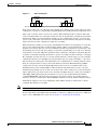
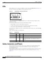
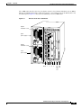
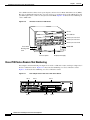
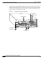
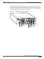
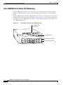
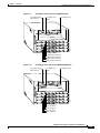
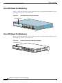
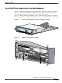
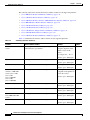
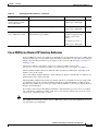
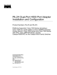
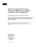
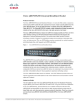
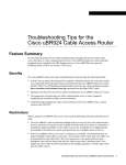
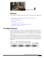
C H A P T E R
1
Overview
This chapter describes the PA-4E1G port adapter and contains the following sections:
•
Port Adapter Overview, page 1-1
•
Interface Specifications, page 1-2
•
LEDs, page 1-4
•
Cables, Connectors, and Pinouts, page 1-4
•
Port Adapter Slot Locations on the Supported Platforms, page 1-7
•
Identifying Interface Addresses, page 1-19
Port Adapter Overview
The PA-4E1G, shown in Figure 1-1 and Figure 1-2, provides up to four E1 synchronous serial interfaces,
which are compatible with and specified by G.703/G.704. The PA-4E1G network interfaces provide a
connection between standard serial interfaces such as V.35 to telephone lines or Post, Telephone, and
Telegraph (PTT) networks. Each PA-4E1G interface operates in full-duplex mode at E1 (2.048 Mbps)
speed.
The PA-4E1G interfaces do not operate in the data terminal equipment (DTE) and data communications
equipment (DCE) modes that are typical of data communications interfaces. The PA-4E1G interfaces
operate with either a line-recovered or an internal clock signal. The default is for a line clock signal that
the interface recovers from the received data stream. The interface can also operate with an internal clock
signal. The PA-4E1G generates the internal clock signal; the interface does not use the motherboard or
system clock.
Figure 1-1
PA-4E1G—75-Ohm, Unbalanced (Front Panel View)
E1 G.703/G.704-75 OHM
EN
LB
LA
A
LB
R
A
LB
R
1
LA
A
LB
R
LA
A
R
2
3
H9600
0
LA
PA-4E1G Serial Port Adapter Installation and Configuration
OL-3065-05
1-1
Chapter 1
Overview
Interface Specifications
Figure 1-2
PA-4E1G—120-Ohm, Balanced (Front Panel View)
E1 G.703/G.704-120 OHM
EN
LB
LA
A
LB
R
LA
LB
LA
A
LB
R
1
LA
A
R
2
3
H9607
0
A
R
Features
The PA-4E1G provides the following features and capabilities:
Note
•
Provides framed and unframed service access, E1 (2.048 Mbps) line speeds over unbalanced 75-ohm
or balanced 120-ohm cable, with 15-pin, D-shell (DB-15) receptacles on the port adapter
•
Operates over E1 leased-line services, and provides ITU-T G.703 with high-density bipolar of order
3 (HDB3) line encoding
•
Operates with either an external or internal clock signal, and runs at wire speed
•
Provides for local and remote loopback testing services
•
Allows you to fractionalize a data stream into a single channel from 64 kilobits per second (kbps)
to 1984 kbps
•
Provides G.704 framing for n x 64-kbps service support (where n = 1 to 31)
•
Support for 4-bit cyclic redundancy check (CRC4) to provide and ensure data integrity
•
Support for point-to-point connections to supported platforms
•
Eliminates the need for a separate, external data termination unit that is typically used to convert
standard serial interfaces, such as V.35, to E1-G.703/G.704
PA-4E1Gs are available as spare parts PA-4E1G-120(=) and PA-4E1G-75(=).
Interface Specifications
Each PA-4E1G interface is available in either balanced (120-ohm) or unbalanced (75-ohm) mode; a
unique port adapter supports each type. Neither the balanced and unbalanced modes nor the balanced
and unbalanced cables are interchangeable; you cannot configure a balanced port to support an
unbalanced line, nor can you attach an interface cable intended for a balanced line to an unbalanced port.
Balanced interfaces typically use three conductors and three signal states: high, low, and ground. The
high and low signals mirror each other. Unbalanced interfaces use only two signals: signal and ground.
You can discover the mode of each interface by examining the agency approval label on each port
adapter, or by using the show controller cbus command.
Following is an example of discovering whether the PA-4E1G is in balanced or unbalanced mode:
Router# show controllers cbus
Serial1/1/0, applique is G.703 Unbalanced
[remainder of displayed text omitted from example]
Serial1/1/1, applique is G.703 Unbalanced
[remainder of displayed text omitted from example]
The PA-4E1G interface is divided into 32 time slots or frames. (See Figure 1-3.)
PA-4E1G Serial Port Adapter Installation and Configuration
1-2
OL-3065-05
Chapter 1
Overview
Interface Specifications
Figure 1-3
Time Slot Diagram
2,048 Mbps
32 time slots = 256 bits
8 bits
H2402
64 kbps
Time slot
0
1
2
3
28 29
30
31
Each of the 32 time slots is an 8-bit frame that transmits data at 64 kbps. Each of these time slots can be
configured to carry data or to remain empty. (The PA-4E1G inserts an idle pattern into empty time slots.)
Time slot 0, or the first 8 bits, is reserved as overhead. The remaining 248 bits (31 frames with 8 bits
each) are designated time slots 1 through 31. Time slot 16 is also designated as a framing slot when using
framed mode. When you use framed mode (G.704), you can configure time slot 16 to carry data and
operate as any of the other slots; therefore, in framed mode time slot 0 must be designated as a framing
signal; time slot 16 can be configured for either data or framing.
With framed mode (G.704) you can specify a bandwidth for the interface by designating 31 of the time
slots for data and reserving time slot 0 for framing (timing). When you use framed mode, you must
designate start and stop time slots; the slots within the start and stop boundaries are used for data, and
the remaining slots are left idle. For example, on an interface with framing set on time slots 1 through
8, the interface carries data within the specified 8 frames, and frames 9 through 31 remain idle. Because
each time slot transmits at 64 kbps, the interface operates at 512 kbps (8 frames x 64 kbps = 512 kbps).
By configuring 16 of the time slots to carry data and the other 16 to remain empty, you can essentially
configure the interface for 1.024 Mbps (by leaving half the time slots empty and unable to carry data).
The system inserts an idle pattern into unused time slots to identify them as overhead (unused for data).
Only one contiguous time slot range can be used. In Private Automatic Branch Exchange (PABX)
systems, time slot 16 is always left unused. By default, time slot 16 is not enabled for data in the
PA-4E1G interface. The command ts16 overrides the default and enables time slot 16 to carry data.
Unframed mode (G.703) uses all 32 time slots for data. None of the 32 time slots are used for framing
signals. This allows each of the 32 time slots to transmit at 64 kbps; therefore, 32 time slots x 64 kbps =
2.048 Mbps. While unframed mode is the default, you can also specify unframed mode with the
command timeslot 0-0, which specifies time slot 0 as the start slot with no stop (ending) time slot;
therefore, all slots are used for data. The no timeslot command restores the default of unframed mode.
Framed mode supports a 4-bit cyclic redundancy check (CRC4), which you enable with a software
command. The default is for no CRC.
Note
The E1-G.703/G.704 interface on PA-4E1G is compliant with BABT 221.
For more information about CRC4 with a PA-4E1G on a VIP, Cisco 7100 series router, Cisco 7200 series
router, or Cisco uBR7200 series router, refer to Chapter 4, “Configuring the PA-4E1G.”
PA-4E1G Serial Port Adapter Installation and Configuration
OL-3065-05
1-3
Chapter 1
Overview
LEDs
LEDs
The PA-4E1G has one row of three status LEDs for each port and one ENABLED LED. (See Figure 1-4.)
The green- and amber-colored LED for each port indicates port status.
Figure 1-4
EN
PA-4E1G LEDs—Partial Front-Panel View
LB
LA
A
R
H9602
0
After system initialization, the ENABLED LED goes on to indicate that the port adapter has been
enabled for operation.
The following conditions must be met before the PA-4E1G is enabled:
•
The PA-4E1G is correctly connected and receiving power.
•
A valid system software image for the port adapter has been downloaded successfully.
•
The system recognizes the PA-4E1G or a VIP with a PA-4E1G.
If any of the above conditions are not met, or if the initialization fails for other reasons, the enabled LED
does not go on.
Table 1-1 lists port LED colors and indications.
Table 1-1
PA-4E1G LEDs
LED Label
Color
State
Meaning
Enabled (EN)
Green
On
Port adapter is enabled for operation.
Loopback (LB)
Amber
On
Line or local loopback is active.
Local alarm (LA)
Amber
On
A loss of signal (LOS), a loss of frame (LOF), an alarm
indication signal (AIS), or any combination of these is
detected.
Remote alarm (RA) Amber
On
A remote source indicates an error on its incoming signal.
Cables, Connectors, and Pinouts
This section describes the port adapter cables for data communications and the PA-4E1G interfaces.
Each PA-4E1G provides up to four 15-pin, D-shell (DB-15) receptacles, which support only
E1-G.703/G.704 interfaces.
The PA-4E1Gs use a DB-15 receptacle for both the balanced and unbalanced ports. The label on the port
adapter indicates if the ports on that port adapter are 75-ohm or 120-ohm. (See Figure 1-1 and
Figure 1-2.)
PA-4E1G Serial Port Adapter Installation and Configuration
1-4
OL-3065-05
Chapter 1
Overview
Cables, Connectors, and Pinouts
The port adapter end of all E1-G.703/G.704 adapter cables is a DB-15 connector. At the network end,
the adapter cable for unbalanced (75-ohm) connections uses a BNC connector. The adapter cables for
balanced (120-ohm) connections use DB-15, twinaxial, or RJ-45 connections to accommodate
connection standards in different countries.
Note
Warning
You must connect the correct type of interface cable for the port to operate.
It is a requirement of the statutory approval of the E1-G.703/G.704 interface that the jackscrews of the
connector backshell are securely screwed down while the port adapter is operating.
Cables for balanced and unbalanced mode are available with the following types of network-end
connectors:
•
Unbalanced (75-ohm) coaxial cables with BNC connectors at the network end, which are used
primarily for connection in the United Kingdom. (See Figure 1-5.)
E1-G.703/G.704 Interface Cable for Unbalanced Connections—with BNC Connectors
and Coaxial Cables
H2421
Figure 1-5
•
Balanced (120-ohm) cable with a DB-15 connector at the network end. (See Figure 1-6.)
E1-G.703/G.704 Interface Cable for Balanced Connections—with DB-15 Connectors on
Both Ends
H2476
Figure 1-6
•
Balanced (120-ohm) twinaxial split cable (with separate transmit and receive cables), each with a
twinaxial connector. (See Figure 1-7.)
E1-G.703/G.704 Interface Cable for Balanced Connections—with Twinaxial
Connectors and Cables
H2424
Figure 1-7
PA-4E1G Serial Port Adapter Installation and Configuration
OL-3065-05
1-5
Chapter 1
Overview
Cables, Connectors, and Pinouts
Cable Product Numbers
Table 1-2 lists the product numbers and descriptions of the E1-G.703/G.704 cables.
Table 1-2
Product Numbers and Descriptions of E1-G.703/G.704 Port Adapter Cables
Cable Product Numbers
Description
CAB-E1-TWINAX(=)1
E1 cable, twinaxial, 120-ohm, balanced, 5 m
CAB-E1-DB15(=)
E1 cable, DB-15, 120-ohm, balanced, 5 m
CAB-E1-BNC(=)
E1 cable, BNC, 75-ohm, unbalanced, 5 m
1. The appended equal sign (=) indicates a spare part.
Cable Distance Limitations
Unbalanced G.703 interfaces allow for a longer maximum cable length than those specified for balanced
circuits. Table 1-3 lists the maximum cable lengths for each E1-G.703/G.704 cable type by the
connector used at the network (non-port adapter) end.
Table 1-3
E1-G.703/G.704 Maximum Cable Lengths
Connection Type
BNC
Twinaxial
Balanced
–
300 m
Unbalanced
600 m
–
PA-4E1G Serial Port Adapter Installation and Configuration
1-6
OL-3065-05
Chapter 1
Overview
Port Adapter Slot Locations on the Supported Platforms
E1-G.703/G.704 Port Adapter Cable Pinouts
Table 1-4 shows the signal pinouts for each type of E1-G.703/G.704 interface cable. All cables use a
DB-15 connector at the port adapter end.
Table 1-4
E1-G.703/G.704 Port Adapter Cable Connector Pinouts
Port Adapter End
Network End
DB-151
DB-152
DB-15 (Null Modem)
Twinaxial2
RJ-452
BNC3
Pin
Signal4
Pin
Pin
Signal
Pin
Signal
Signal
9
Tx tip
1
3
Rx tip
4
Rx tip
Tip
2
Tx ring
9
11
Rx ring
5
Rx ring
Shield
10
Tx shield
2
4
Rx shield
6
Rx shield
–
8
Rx tip
3
1
Tx tip
1
Tx tip
Tip
15
Rx ring
11
9
Tx ring
2
Tx ring
Shield
7
Rx shield
4
2
Tx shield
3
Tx shield
–
1. Any pins not described in this table are not connected.
2. 120-ohm, balanced cable
3. 75-ohm, unbalanced cable
4. Tx = transmit, Rx = receive
Port Adapter Slot Locations on the Supported Platforms
This section discusses port adapter slot locations on the supported platforms. The illustrations that
follow summarize slot location conventions on each platform:
•
Cisco 7000 Series Routers VIP Slot Numbering, page 1-8
•
Cisco 7100 Series Routers Slot Numbering, page 1-10
•
Cisco 7200 Series Routers and Cisco 7200 VXR Routers Slot Numbering, page 1-11
•
Cisco uBR7200 Series Router Slot Numbering, page 1-14
•
Cisco 7201 Router Slot Numbering, page 1-16
•
Cisco 7301 Router Slot Numbering, page 1-16
•
Cisco 7304 PCI Port Adapter Carrier Card Slot Numbering, page 1-17
•
Cisco 7401ASR Router Slot Numbering, page 1-18
•
Cisco 7500 Series Routers VIP Slot Numbering, page 1-18
PA-4E1G Serial Port Adapter Installation and Configuration
OL-3065-05
1-7
Chapter 1
Overview
Port Adapter Slot Locations on the Supported Platforms
Cisco 7000 Series Routers VIP Slot Numbering
Port adapters are supported on the VIPs (versatile interface processors) used in Cisco 7000 series routers.
In the Cisco 7000 router, the VIP motherboard is installed vertically in the VIP slot.In the Cisco 7010
router, the VIP motherboard is installed horizontally in the VIP slot. A port adapter can be installed in
either bay (port adapter slot 0 or 1) on the VIP. The bays are numbered from left to right on the VIP.
Figure 1-8 shows the slot numbering of a VIP.
Figure 1-8
VIP Slot Locations
Port adapter slot 1
29328
Port adapter slot 0
Port adapter
handles not
shown
PA-4E1G Serial Port Adapter Installation and Configuration
1-8
OL-3065-05
Chapter 1
Overview
Port Adapter Slot Locations on the Supported Platforms
Cisco 7000 routers have five slots for port adapters, and two slots for Route Switch Processors (RSPs).
The slots are numbered from left to right. You can place a port adapter in any of the VIP interface slots
(slot 0 through 4). Figure 1-9 shows the slot numbering on a Cisco 7000 router.
Figure 1-9
VIP Slots in the Cisco 7000 Router
Captive
installation screw
DC
AC
FA
IL
PO
WE
R
Upper
power supply
I
O
Captive
installation screw
DC
FA
IL
PO
WE
R
H2358
AC
Lower
power supply
I
O
Slot 0
1
2
3
4
SP RP
or
slot
SSP
slot
PA-4E1G Serial Port Adapter Installation and Configuration
OL-3065-05
1-9
Chapter 1
Overview
Port Adapter Slot Locations on the Supported Platforms
Cisco 7010 routers have three slots for port adapters, and two slots for Route Switch Processors (RSPs).
The slots are numbered from bottom to top. You can place a port adapter in any of the VIP interface slots
(slot 0 through 2). Slots 3 and 4 are always reserved for RSPs. Figure 1-10 shows the slot numbering on
a Cisco 7010 router.
Figure 1-10
VIP Slots in the Cisco 7010 Router
RP slot
SP or SSP slot
Interface processor slot 2
Interface processor slot 1
Interface processor slot 0
H2359
Power switch
Chassis ground
screw
Power receptacle
DC OK LED
AC-input power supply
Cisco 7100 Series Routers Slot Numbering
Port adapters can be installed in port adapter slot 3 in Cisco 7120 series routers, and in port adapter slot 4
in Cisco 7140 series routers. Figure 1-11 shows the slot numbering on a Cisco 7120 series router.
Figure 1-12 shows the slot numbering on a Cisco 7140 series router.
Figure 1-11
Port Adapter Slots in the Cisco 7120 Series Router
Slot 5
Slot 3
Slot 4
SLOT 0
SLOT 1
PWR
ACT ACT
0
FE 0 / 0
I
E3
EN
TX
FE
0/1
LNK LNK
0
1
CONS
AUX
SYS
RDY
RX
RX
2
CEL CAR ALM
7120 - AE3
Slot 1
Slot 0
18498
5
Slot 2
PA-4E1G Serial Port Adapter Installation and Configuration
1-10
OL-3065-05
Chapter 1
Overview
Port Adapter Slot Locations on the Supported Platforms
Figure 1-12
Port Adapter Slots in the Cisco 7140 Series Router
Slot 5
Slot 3
Slot 4
AC OK
DC OK
OTF
RESET
PWR
ACT ACT
EN
5
0
FE 0 / 0
I
SLOT 1
EN
RX
RX
155 - MM
TX
CONS
155 - MM
RX
TX
RX
EN
CEL CAR ALM
FE 0 / 1
LNK LNK
0
1
AC OK
SYS
RDY
DC OK
OTF
2
CEL CAR ALM
7140 - 2MM3
Slot 0
Slot 1
AUX
18499
SM-ISM
SLOT 0
BOOT
ERROR
Slot 2
Cisco 7200 Series Routers and Cisco 7200 VXR Routers Slot Numbering
Cisco 7202 routers have two port adapter slots. The slots are numbered from left to right. You can place
a port adapter in either of the slots (slot 1 or slot 2). Figure 1-13 shows the slot numbering on a
Cisco 7202 router.
Figure 1-13
Port Adapter Slots in the Cisco 7202 Router
(blank port
adapter installed)
Cisco 7200 SERIES
2
CLA
TX
S
LA S 1
SE LA
P R RP S E
O U RO R P
IT DUK RO
LA T DU
S E DE C T
PR
R RK
OD
DE LA
UC
CLA SS
TO
E
SS 1
LA
E
SE
1
R
CL
AS
S
1
RX
15
5-S
MI
T
SE
RE
U
PO
O WE
K
R
CP
0
EJ
EC
T
SL
O
T
PC
M
C
IA
1O
EN
AB
LE
D
0
SL
O
T
1
FAST ETHERNET INPUT/OUTPUT CONTROLLER
11603
EN
1
AB
LE
D
RX
CE
RX LLS
CA
RX RRIE
AL R
AR
M
ENHANCED ATM
PA-4E1G Serial Port Adapter Installation and Configuration
OL-3065-05
1-11
Chapter 1
Overview
Port Adapter Slot Locations on the Supported Platforms
Cisco 7204 routers and Cisco 7204VXR routers have four slots for port adapters, and one slot for an
input/output (I/O) controller. The slots are numbered from the lower left to the upper right, beginning
with slot 1 and continuing through slot 4. You can place a port adapter in any of the slots (slot 1 through
slot 4). Slot 0 is always reserved for the I/O controller. Figure 1-14 shows the slot numbering on a Cisco
7204 router. The Cisco 7204VXR router is not shown.
Figure 1-14
Port Adapter Slots in the Cisco 7204 Router
Port adapter slot 4
Port adapter slot 2
Blank port adapter
Cisco 7200 SERIES
4
LIN
0
MII
K
EN
AB
LE
D
0
TX
2
RX
4
TX
3
RX
TX
RX
2
1
TX
RX
TX
EN
LB
CD
RC
RD
TC
TD
LB
CD
RC
RD
TC
TD
LB
CD
RC
RD
TC
TD
LB
CD
RC
EN
RD
TC
ETHERNET-10BFL
RX
3
2
3
LINK
1
0
2
1
0
EN
AB
LE
D
3
FAST SERIAL
TD
RJ
45
FAST ETHERNET
ETHERNET 10BT
SE
RE
II
0
D
LE
AB
R
E J4
N 5
R
LINJ4
K5
M
E II
N
T
0
T
EC
O
EJ
SL
PC
M
CIA
EN
R
W
P K
1O O
H7399
45
CP
RJ-
U
M
FE
SL
O
T
1
T
1
FAST ETHERNET INPUT/OUTPUT CONTROLLER
Port adapter slot 3
Port adapter slot 1
Port adapter slot 0
PA-4E1G Serial Port Adapter Installation and Configuration
1-12
OL-3065-05
Chapter 1
Overview
Port Adapter Slot Locations on the Supported Platforms
Cisco 7206 routers and Cisco 7206VXR routers have six slots for port adapters, and one slot for an
input/output (I/O) controller. The slots are numbered from the lower left to the upper right, beginning
with slot 1 and continuing through slot 6. You can place a port adapter in any of the six slots (slot 1
through slot 6). Slot 0 is always reserved for the I/O controller. Figure 1-15 shows the slot numbering
on a Cisco 7206 router. The Cisco 7206VXR router is not shown.
Figure 1-15
Port Adapter Slots in the Cisco 7206 Router
3
2
1
0
6
TOKEN RING
5
FAST ETHERNET
4
5
RJ4
MII
0
LIN
K
D
LE
AB
EN
J-4
2
TX
RX
4
TX
RX
3
TX
RX
5
0
T
T
O
M N
E
SL
EC
EJ
IA
C
M
PC
EN
AB
LE
D
0
R
II
Port adapter slot 5
Port adapter slot 3
Port adapter slot 1
5
J-4
R EN
R
5
PW
J-4
R INK O K
1 O
L
28329
FE
M
II
T
O
SL
2
RX
1
FAST ETHERNET INPUT/OUTPUT CONTROLLER
1
Cisco 7200
Series
TX
EN
RX
1
0
7
6
5
4
3
2
1
0
ETHERNET-10BFL
TX
3
2
3
LINK
1
0
2
1
SERIAL-V.35
EN
3
EN
AB
LE
0
D
ETHERNET 10BT
Port adapter slot 6
Port adapter slot 4
Port adapter slot 2
Port adapter slot 0
PA-4E1G Serial Port Adapter Installation and Configuration
OL-3065-05
1-13
Chapter 1
Overview
Port Adapter Slot Locations on the Supported Platforms
Cisco uBR7200 Series Router Slot Numbering
The Cisco uBR7223 router has one port adapter slot (slot 1). Slot 0 is always reserved for the I/O
controller—if present. Figure 1-16 shows the slot numbering of port adapters on a Cisco uBR7223
router.
The Cisco uBR7246 router and Cisco uBR7246VXR router have two port adapter slots (slot1 and slot
2). Slot 0 is always reserved for the I/O controller—if present. Figure 1-17 shows the slot numbering of
port adapters on a Cisco uBR7246 router. Figure 1-18 shows the slot numbering of port adapters on a
Cisco uBR7246VXR router.
Figure 1-16
Port Adapter Slots in the Cisco uBR7233 Router
Port adapter slot 0
(I/O controller)
uBR - MCI6
5
uBR - MCI6
D
S
2
U
S
U
S
U
S
D
LE
U
S
AB
1
EN
0
Cable modem card slot 2
Cable modem card slot 3
15745
5
D
S
4
U
S
3
U
S
2
U
S
1
U
S
U
S
D
LE
AB
0
EN
U
S
Port adapter slot 1
PA-4E1G Serial Port Adapter Installation and Configuration
1-14
OL-3065-05
Chapter 1
Overview
Port Adapter Slot Locations on the Supported Platforms
Port Adapter Slots in the Cisco uBR7246 Router
5
uBR - MCI6
5
uBR - MCI6
5
uBR - MCI6
5
uBR - MCI6
S
S
Port adapter slot 2
D
U
S
4
U
S
3
U
2
U
S
1
U
D
0
U
LE
Port adapter slot 1
(blank)
S
S
D
U
S
2
U
S
D
1
U
U
LE
0
S
S
D
U
S
2
U
S
D
1
U
U
LE
0
D
H11323
S
S
U
S
2
U
S
D
1
U
U
LE
0
EN
AB
S
EN
AB
S
EN
AB
S
EN
AB
S
Port adapter slot 0
(I/O controller)
S
Figure 1-17
Cable modem card slot 3
Cable modem card slot 4
Cable modem card slot 5
Cable modem card slot 6
Figure 1-18
Port Adapter Slots in the Cisco uBR7246VXR Router
Port adapter slot 0
(I/O controller)
Port adapter slot 1
(blank)
Port adapter slot 2
uBR - CLK-T1
SEC
LOS
ACTIVE
5
uBR - MCI6
5
uBR - MCI6
5
uBR - MCI6
5
uBR - MCI6
S
S
D
4
U
S
3
U
S
U
S
2
U
S
D
1
U
U
LE
0
FAULT
S
S
D
U
S
2
U
S
D
1
U
U
LE
0
S
S
D
U
S
2
U
S
D
1
U
U
LE
0
31501
S
D
S
2
U
S
1
U
S
U
D
LE
U
0
EN
AB
S
EN
AB
S
EN
AB
S
EN
AB
S
FREERUN
ER
Line card slot 3
Line card slot 4
Line card slot 5
Line card slot 6
PA-4E1G Serial Port Adapter Installation and Configuration
OL-3065-05
1-15
Chapter 1
Overview
Port Adapter Slot Locations on the Supported Platforms
Cisco 7201 Router Slot Numbering
Figure 1-19 shows the front view of a Cisco 7201 router with a port adapter installed. There is only one
port adapter slot (slot 1) in a Cisco 7201 router.
Figure 1-19
Port Adapter Slot in the Cisco 7201 Router
Port adapter slot
D
R
LE LS RIE M
AB EL AR AR
EN RX C RX C X AL
R
ATM
Cisco 720
1
PA
SLOT 1
LINK/ACTV
SFP
CONSOLE
RJ45 EN
LINK/ACTV
TX SFP
RX
LINK/ACTV
SFP
LINK/ACTV
TX SFP
RX
GE 0/0
230308
RJ45 EN
MNGMNT
USE ONLY
GE 0/1
GE 0/2
ALARM
GE 0/3
AUX
FE 0/0
FE
LINK
PWR OK
0
COMPACT
FLASH
STATUS
CF
ACTV
Cisco 7301 Router Slot Numbering
Figure 1-20 shows the front view of a Cisco 7301 router with a port adapter installed. There is only one
port adapter slot (slot 1) in a Cisco 7301 router.
Figure 1-20
Cisco 7301 Router with a Port Adapter Installed
Port adapter slot
D
LE
AB
EN
S IER
LL R RM
CE CAR LA
RX RX RX A
ATM
GIGABIT ETHER
NET
RJ45 EN
0/0
LINK
TX GBIC
GIGABIT ETHER
NET
RX
RJ45 EN
0/1
LINK
TX GBIC
GIGABIT ETHER
NET
RX
RJ45 EN
0/2
LINK
TX GBIC
AUX
RX
CISCO 7400
CISCO 7411SERIES
CONSOLE
ALARM
COMPACT
FLASH
STATUS
100-24 0V,
2A, 50/60
Hz
24V=9 A,
48 - 60V=5
A
84988
SLOT 1
PA-4E1G Serial Port Adapter Installation and Configuration
1-16
OL-3065-05
Chapter 1
Overview
Port Adapter Slot Locations on the Supported Platforms
Cisco 7304 PCI Port Adapter Carrier Card Slot Numbering
The Cisco 7304 PCI Port Adapter Carrier Card installs in Cisco 7304 router module slots 2 through 5.
Figure 1-21 shows a Cisco 7304 PCI Port Adapter Carrier Card with a port adapter installed. The
Cisco 7304 PCI Port Adapter Carrier Card accepts one single-width port adapter.
Figure 1-22 shows the module slot numbering on a Cisco 7304 router. The port adapter slot number is
the same as the module slot number. Slot 0 and slot 1 are reserved for the NPE module or NSE module.
Figure 1-21
7300-C
Cisco 7304 PCI Port Adapter Carrier Card—Port Adapter Installed
C-PA
84653
D
R
LE LS RIE M
AB CEL AR AR
EN RX RX C X AL
R
OIR
STATUS
7300 PA
ATM
CARRIER
Figure 1-22
Module Slots on the Cisco 7304 Router
Slot 4
7300-2
OC3AT
M-MM
TX
OIR
0
Slot 5
RX
STATUS
TX
2-PORT
OC3 ATM
CARRIER
ALARM/
9K-10C
1
RX
MM
48
ACTIVE/
LOOPBA
CK
CARRIER
ALARM/
ACTIVE/
LOOPBA
CK
TX
OIR
RX
STATUS
1-POR
T OC48
POS w/
9K-40C3
/POS-M
M
SMSR
OIR
STATUS
4-POR
T OC3
POS
0
1
2
3
w/ MM
CARRIE
R/
ALARM
70550
ACTIVE/
LOOPBA
CK
Slot 0
Slot 2
Slot 3
Slot 1
PA-4E1G Serial Port Adapter Installation and Configuration
OL-3065-05
1-17
Chapter 1
Overview
Port Adapter Slot Locations on the Supported Platforms
Cisco 7401ASR Router Slot Numbering
Figure 1-23 shows the front view of a Cisco 7401ASR router with a port adapter installed. There is only
one port adapter slot (slot 1) in a Cisco 7401ASR router.
Figure 1-23
D
R
LE LS RIE M
AB EL AR AR
EN RX C RX C X AL
TX
RX
ENHANCED
ATM
57680
R
Port Adapter Slot in the Cisco 7401ASR Router
Cisco 7500 Series Routers VIP Slot Numbering
Port adapters are supported on the VIPs (versatile interface processors) used in Cisco 7500 series
routers. In the Cisco 7505 router, the VIP motherboard is installed horizontally in the VIP slot. In the
Cisco 7507 router and Cisco 7513 router, the VIP motherboard is installed vertically in the VIP slot. A
port adapter can be installed in either bay (port adapter slot 0 or 1) on the VIP. The bays are numbered
from left to right on the VIP. Figure 1-24 shows the slot numbering on a VIP.
Figure 1-24
VIP Slot Locations
Port adapter slot 1
29328
Port adapter slot 0
Port adapter
handles not
shown
PA-4E1G Serial Port Adapter Installation and Configuration
1-18
OL-3065-05
Chapter 1
Overview
Identifying Interface Addresses
Cisco 7505 routers have four slots for port adapters, and one slot for an RSP. The slots are numbered
from bottom to top. You can place a port adapter in any of the VIP interface slots (slot 0 through 3). One
slot is always reserved for the RSP. Figure 1-25 shows the slot numbering on a Cisco 7505 router.
Figure 1-25
VIP Slots in the Cisco 7505 Router
VIP in interface processor slot 3
T
SE
E
OL
NS
CO
U
RE
CP
EC
EJ
AL
RM
NO
SL S L O
OT T
0 1
T
HA
LT
ROUTE SWITCH PROCESSOR
Slot 3
Slot 2 Interface
processor
Slot 1 slots
29619
Slot 0
Cisco 7507 routers have five slots for port adapters, and two slots for RSPs. The slots are numbered from
left to right. You can place a port adapter in any of the VIP interface slots (slot 0, 1, 4, 5, or 6). Slots 2
and 3 are always reserved for RSPs. The Cisco 7507 router is not shown.
Cisco 7513 routers have eleven slots for port adapters, and two slots for RSPs. The slots are numbered
from left to right. You can place a port adapter in any of the VIP interface slots (slots 0 through 5, or
slots 9 through 12). Slots 6 and 7 are always reserved for RSPs. The Cisco 7513 router is not shown.
Identifying Interface Addresses
This section describes how to identify interface addresses for the PA-4E1G in supported platforms.
Interface addresses specify the actual physical location of each interface on a router or switch.
Interfaces on a PA-4E1G installed in a router maintain the same address regardless of whether other port
adapters are installed or removed. However, when you move a port adapter to a different slot, the first
number in the interface address changes to reflect the new port adapter slot number.
Interfaces on a PA-4E1G installed in a VIP maintain the same address regardless of whether other
interface processors are installed or removed. However, when you move a VIP to a different slot, the
interface processor slot number changes to reflect the new interface processor slot.
PA-4E1G Serial Port Adapter Installation and Configuration
OL-3065-05
1-19
Chapter 1
Overview
Identifying Interface Addresses
The following subsections describe the interface address formats for the supported platforms:
•
Cisco 7000 Series Routers VIP Interface Addresses, page 1-21
•
Cisco 7100 Series Routers Interface Addresses, page 1-22
•
Cisco 7200 Series Routers and Cisco 7200 VXR Routers Interface Addresses, page 1-22
•
Cisco uBR7200 Series Routers Interface Addresses, page 1-22
•
Cisco 7201 Router Interface Addresses, page 1-22
•
Cisco 7301 Router Interface Addresses, page 1-23
•
Cisco 7304 PCI Port Adapter Carrier Card Interface Addresses, page 1-23
•
Cisco 7401ASR Router Interface Addresses, page 1-23
•
Cisco 7500 Series Routers VIP Interface Addresses, page 1-23
Table 1-5 summarizes the interface address formats for the supported platforms.
Table 1-5
Identifying Interface Addresses
Platform
Interface Address Format
Numbers
Syntax
VIP in Cisco 7000 series
routers
Interface-processor-slot-number/port-adapter-slotnumber/interface-port-number
Interface processor slot—0
through 4 (depends on the
number of slots in the
router)
3/1/0
Port adapter slot— 0 or 1
Interface port—0 through 3
Cisco 7120 series router
Port-adapter-slot-number/interface-port-number
Port adapter slot—always 3
3/1
Interface port—0 through 3
Cisco 7140 series router
Port-adapter-slot-number/interface-port-number
Port adapter slot—always 4
4/0
Interface port—0 through 3
Cisco 7200 series routers
and Cisco 7200 VXR
routers (Cisco 7202,
Cisco 7204,
Cisco 7204VXR,
Cisco 7206,
Cisco 7206VXR)
Port-adapter-slot-number/interface-port-number
Cisco 7201 router
Port-adapter-slot-number/interface-port-number
Port adapter slot—1 through 1/0
6 (depends on the number of
slots in the router)1
Interface port—0 through 3
Port adapter slot—always 1
1/0
Interface port—0 through 3
Cisco uBR7223 router
Port-adapter-slot-number/interface-port-number
Port adapter slot—always 11 1/0
Interface port—0 through 3
Cisco uBR7246 and
Cisco uBR7246 VXR
routers
Port-adapter-slot-number/interface-port-number
Cisco 7301 routers
Port-adapter-slot-number/interface-port-number
Port adapter slot—1 or 21
1/0
Interface port—0 through 3
Port adapter slot—always 1
1/0
Interface port—0 through 3
PA-4E1G Serial Port Adapter Installation and Configuration
1-20
OL-3065-05
Chapter 1
Overview
Identifying Interface Addresses
Table 1-5
Identifying Interface Addresses (continued)
Platform
Interface Address Format
Numbers
Syntax
Cisco 7304 PCI Port
Adapter Carrier Card in
Cisco 7304 routers
Module-slot-number/interface-port-number
Module slot—2 through 5
3/0
Cisco 7401ASR routers
Port-adapter-slot-number/interface-port-number
Interface port—0 through 3
Port adapter slot—always 1
1/0
Interface port—0 through 3
VIP in Cisco 7000 series or
Cisco 7500 series routers
Interface-processor-slot-number/port-adapter-slotnumber/interface-port-number
Interface processor slot—0
through 12 (depends on the
number of slots in the
router)
3/1/0
Port adapter slot—0 or 1
Interface port—0 through 3
1. Port adapter slot 0 is reserved for the Fast Ethernet port on the I/O controller (if present).
Cisco 7000 Series Routers VIP Interface Addresses
In Cisco 7000 series routers, port adapters are installed on a versatile interface processor (VIP), which
installs in interface processor slots 0 through 4 (depending on the number of slots in the router). The port
adapter can be installed in either bay (port adapter slot 0 or 1) on the VIP. See Figure 1-8, Figure 1-9,
and Figure 1-10
The interface address for the VIP is composed of a three-part number in the format
interface-processor-slot-number/port-adapter-slot-number/interface-port-number. See Table 1-5.
The first number identifies the slot in which the VIP is installed (slot 0 through 4, depending on the
number of slots in the router).
The second number identifies which bay on the VIP the port adapter is installed (0 or 1). The bays are
numbered from left to right on the VIP.
The third number identifies the physical port number (interface port number) on the port adapter. The
port numbers always begin at 0 and are numbered from left to right. The number of additional ports
depends on the number of ports on the port adapter. The PA-4E1G is a four-port port adapter, therefore
the port can be 0 through 3.
For example, if the four-port PA-4E1G is installed in a VIP in interface processor slot 3, port adapter
slot 1, the interface addresses would be 3/1/0, 3/1/1. 3/1/2, and 3/1/3 (interface processor slot 3, port
adapter slot 1, and interfaces 0,1, 2, and 3).
Note
Although the processor slots in the 7-slot Cisco 7000 are vertically oriented and those in the 5-slot
Cisco 7010 are horizontally oriented, all Cisco 7000 series routers use the same method for processor
slot and interface port numbering.
PA-4E1G Serial Port Adapter Installation and Configuration
OL-3065-05
1-21
Chapter 1
Overview
Identifying Interface Addresses
Cisco 7100 Series Routers Interface Addresses
In Cisco 7120 series router, port adapters are installed in port adapter slot 3. See Figure 1-11. In the
Cisco 7140 series router, port adapters are installed in port adapter slot 4. See Figure 1-12.
The interface address is composed of a two-part number in the format
port-adapter-slot-number/interface-port-number. See Table 1-5. For example, if a four-port PA-4E1G is
installed on a Cisco 7120 router, the interface addresses would be 3/0 through 3/3. If a four-port
PA-4E1G is installed on a Cisco 7140 router, the interface addresses would be 4/0 through 4/3.
Cisco 7200 Series Routers and Cisco 7200 VXR Routers Interface Addresses
In Cisco 7200 series routers and Cisco 7200 VXR routers, port adapter slots are numbered from the
lower left to the upper right, beginning with slot 1 and continuing through slot 2 for the Cisco 7202,
slot 4 for the Cisco 7204 and Cisco 7204VXR, and slot 6 for the Cisco 7206 and Cisco 7206VXR. Port
adapters can be installed in any available port adapter slot from 1 through 6 (depending on the number
of slots in the router). (Slot 0 is reserved for the I/O controller.) See Figure 1-13, Figure 1-14, and
Figure 1-15
The interface address is composed of a two-part number in the format
port-adapter-slot-number/interface-port-number. See Table 1-5. For example, if a four-port PA-4E1G is
installed in slot 1of a Cisco 7200 series router, the interface addresses would be 1/0 through 1/3.
Cisco uBR7200 Series Routers Interface Addresses
In the Cisco uBR7223 router, only one slot accepts port adapters and it is numbered slot 1. See
Figure 1-16
In the Cisco uBR7246 router and Cisco uBR7246VXR router, port adapters can be installed in two port
adapter slots (slot1 and slot 2). Slot 0 is always reserved for the I/O controller—if present. See
Figure 1-17 and Figure 1-18.
The interface address is composed of a two-part number in the format
port-adapter-slot-number/interface-port-number. See Table 1-5. For example, if a four-port PA-4E1G is
installed in slot 1of a Cisco uBR7223 series router, the interface addresses would be 1/0 through 1/3. If
a four-port PA-4E1G is installed in slot 2 of a Cisco uBR7246 or Cisco uBR7246VXR router, the
interface addresses would be 2/0 through 2/3.
Cisco 7201 Router Interface Addresses
In the Cisco 7201 router, only one slot accepts port adapters and it is numbered as slot 1. See
Figure 1-19.
The interface address is composed of a two-part number in the format
port-adapter-slot-number/interface-port-number. See Table 1-5. For example, if a four-port PA-4E1G is
installed in a Cisco 7201 router, the interface addresses would be 1/0 through 1/3.
PA-4E1G Serial Port Adapter Installation and Configuration
1-22
OL-3065-05
Chapter 1
Overview
Identifying Interface Addresses
Cisco 7301 Router Interface Addresses
In the Cisco 7301 router, only one slot accepts port adapters and it is numbered as slot 1. See
Figure 1-20.
The interface address is composed of a two-part number in the format
port-adapter-slot-number/interface-port-number. See Table 1-5. For example, if a four-port PA-4E1G is
installed in a Cisco 7301 router, the interface addresses would be 1/0 through 1/3.
Cisco 7304 PCI Port Adapter Carrier Card Interface Addresses
In the Cisco 7304 router, port adapters are installed in a Cisco 7304 PCI port adapter carrier card, which
installs in Cisco 7304 router module slots 2 through 5. The port adapter slot number is the same as the
module slot number. See Figure 1-21 and Figure 1-22.
The interface address is composed of a two-part number in the format
module-slot-number/interface-port-number. See Table 1-5. For example, if a four-port PA-4E1G is
installed in the Cisco 7304 PCI port adapter carrier card in Cisco 7304 router module slot 3, the interface
addresses would be 3/0 through 3/3.
Cisco 7401ASR Router Interface Addresses
In the Cisco 7401ASR router, only one slot accepts port adapters and it is numbered as slot 1. See
Figure 1-23.
The interface address is composed of a two-part number in the format
port-adapter-slot-number/interface-port-number. See Table 1-5. For example, if a four-port PA-4E1G is
installed in a Cisco 7401ASR router, the interface addresses would be 1/0 through 1/3.
Cisco 7500 Series Routers VIP Interface Addresses
In Cisco 7000 series routers and Cisco 7500 series routers, port adapters are installed on a versatile
interface processor (VIP), which installs in interface processor slots 0 through 12 (depending on the
number of slots in the router). The port adapter can be installed in either bay (port adapter slot 0 or 1)
on the VIP. See Figure 1-24, and Figure 1-25.
The interface address for the VIP is composed of a three-part number in the format
interface-processor-slot-number/port-adapter-slot-number/interface-port-number. See Table 1-5.
The first number identifies the slot in which the VIP is installed (slot 0 through 12, depending on the
number of slots in the router).
The second number identifies the bay (port adapter slot) on the VIP in which the port adapter is installed
(0 or 1). The bays are numbered from left to right on the VIP.
The third number identifies the physical port number (interface port number) on the port adapter. The
port numbers always begin at 0 and are numbered from left to right. The number of additional ports
depends on the number of ports on the port adapter. The PA-4E1G is a four-port port adapter, therefore
the port can be 0 through 3.
PA-4E1G Serial Port Adapter Installation and Configuration
OL-3065-05
1-23
Chapter 1
Overview
Identifying Interface Addresses
For example, if a four-port PA-4E1G is installed in a VIP in interface processor slot 3, port adapter slot 1,
the interface addresses would be 3/1/0 through 3/1/3 (interface processor slot 3, port adapter slot 1, and
interfaces 0, 1, 2 and3).
Note
Although the processor slots in the 7-slot Cisco 7507 and the 13-slot Cisco 7513 and Cisco 7576 are
vertically oriented and those in the 5-slot Cisco 7505 are horizontally oriented, all Cisco 7500 series
routers use the same method for slot and interface port numbering.
PA-4E1G Serial Port Adapter Installation and Configuration
1-24
OL-3065-05