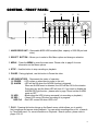
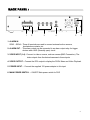
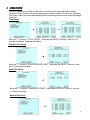
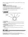
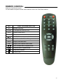
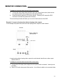
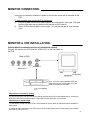
1
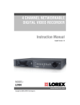
4-CHANNEL DVR Instruction Manual English Version 3.0 BEFORE OPERATING THIS SYSTEM, PLEASE READ THIS MANUAL THOROUGHLY AND RETAIN IT FOR FUTURE REFERENCE MODEL: L154-81 www.lorexcctv.com Copyright ©2006 Lorex Technology Inc Thank you for purchasing the 4 channel DVR from Lorex Techonolgy Inc. The DVR converts analog video into digital format and records them on a hard disk drive depending on the system purchased. Digital video allows you to quickly access and search for a specific time segment or event which has been recorded. The DVR supports 2 HDD units with a maximum capacity of 250 GB per hard drive. To learn more about this system or to find out more about our products available, please visit our website at: www.lorexcctv.com CAUTION ! RISK OF ELECTRIC SHOCK. DO NOT OPEN. CAUTION! TO REDUCE THE RISK OF ELECTRIC SHOCK, DO NOT REMOVE COVER (OR BACK). NO USER-SERVICEABLE PARTS INSIDE. REFER SERVICING TO QUALIFIED SERVICE PERSONNEL. Explanation of two Symbols The lightning flash with arrowhead symbol, within an equilateral triangle, is intended to alert the user to the presence of un-insulated "dangerous voltage" within the product's enclosure that may be of sufficient magnitude to constitute a risk of electric shock to persons. ! The exclamation point within an equilateral triangle is intended to alert the user to the presence of important operating and maintenance (servicing) instructions in the literature accompanying the appliance. THE GRAPHIC SYMBOLS WITH SUPPLEMENTAL MARKING ARE ON THE BOTTOM OF THE SYSTEM. “WARNING – TO PREVENT FIRE OR SHOCK HAZARD, DO NOT EXPOSE THE UNIT TO RAIN OR MOISTURE” -i- NOTE This equipment has been certified and found to comply with the limits regulated by FCC, EMC and LVD. Therefore, it is designed to provide reasonable protection against interference and will not cause interference with other appliance usage. However, it is imperative that user follows this manual's guidelines to avoid improper usage which may result in damage to the unit, electrical shock and fire hazard or injury. In order to improve the feature functions and quality of this product, the specifications are subject to change without notice from time to time. FCC CLASS B NOTICE Note: This equipment has been tested and found to comply with the limits For a Class B digital device, pursuant to Part 15 of the FCC Rules. These limits are designed to provide reasonable protection against harmful interference in a residential installation. This equipment generates, uses and can radiate radio frequency energy and, if not installed and used in accordance with the instruction, may cause harmful interference to radio communications. However, there is no guarantee that interference will not occur in a particular installation. If this equipment does cause harmful interference to radio or television reception, (which can be determined by turning the equipment off and on), the user is encouraged to try to correct the interference by one or more of the following measures: • Increase the separation between the equipment and the camera and/or monitor. • Connect the equipment into an outlet on a circuit different from that to which the monitor is connected. • Consult the dealer or an experienced radio or television technician for help. LOREX TECHNOLOGY INC. www.lorexcctv.com -ii- CONTENTS: GENERAL PRECAUTIONS ----------------------------------------------------------------------- 1 FEATURES ------------------------------------------------------------------------------------------- 2 SYSTEM CONTENTS ----------------------------------------------------------------------------- 3 GETTING STARTED ------------------------------------------------------------------------------- 4 CONTROLS - FRONT PANEL ------------------------------------------------------------------- 5 BACK PANEL --------------------------------------------------------------------- 7 MAIN MENU CONTROL--------------------------------------------------------------------------- 8 OPERATION CAMERA SELECT (1-4) -------------------------------------------------------- 14 RECORDING ---------------------------------------------------------------------- 14 SEARCH MENU ------------------------------------------------------------------ 15 PLAYBACK------------------------------------------------------------------------ 16 KEY LOCK ------------------------------------------------------------------------ 16 REMOTE CONTROL------------------------------------------------------------------------------ 17 CAMERA INSTALLATION------------------------------------------------------------------------ 18 MONITOR CONNECTION--------------------------------------------------------qt---------------- 18 MONITOR & VCR INSTALLATION------------------------------------------------------------- 21 TROUBLESHOOTING ---------------------------------------------------------------------------- 23 TECHNICAL SPECIFICATIONS --------------------------------------------------------------- 24 OPTIONAL ACCESSORIES--------------------------------------------------------------------- 25 APPENDIX # 1 – INSTALLING THE HDD---------------------------------------------------- 26 APPENDIX #2 – RECORDING TIME ( IN HOURS ) --------------------------------------- 29 APPENDIX #3 – RECORDING TIME ( IN HOURS ) --------------------------------------- 30 CARE & MAINTENANCE--------------------------------------------------------------------------- 31 -iii- GENERAL PRECAUTIONS: 1. 2. 3. 4. 5. 6. 7. 8. 9. 10. 11. 12. 13. 14. Read Instructions All of the safety and operating instructions should be read and understood before the product is used. Retain Instructions The safety and operating instructions should be retained for future reference. Heed Warnings All warnings on the product and the instruction manual should be followed. Follow Instructions All operating and use instructions should be followed for optimal performance Cleaning Disconnect this video product from the power supply before cleaning. Do not use liquid cleaners or aerosol cleaners. Use a damp cloth for cleaning. Attachments Do not use attachments not recommended by the video product manufacturer as they may cause hazards. Water and Moisture Do not use this product near water - for example, near a bathtub, wash bowl, kitchen sink, wet basement, or near a swimming pool. Accessories Use this product only with a stand, tripod, bracket or table recommended by the manufacturer or sold with the product. Any mounting of the product should follow the manufacturer’s instructions. Ventilation This product should never be placed near or over a radiator or heat register. This product should not be placed in a built-in installation, such as a book case or rack, unless proper ventilation is provided or the Manufacturer’s instructions have been adhered to. Power Source This product should be operated from the type of Power source indicated by the marking label. If you are not sure of the type of power supply to your location, consult your product dealer or your local Power company Power Cord Protection Power supply cords should not be routed so that they are likely to be walked on or pinched by items placed on or near them Lightning For added protection, unplug this product from its outlet during a lightning storm. This will prevent damage to the video product due to lightning and power surges Overloading To avoid the risk of fire and electric shock, do not plug this product into an over-loaded power supply. Object and Liquid Entry Never push objects into the openings of this product as they may touch dangerous voltage points that may result in fire or electric shock. Never spill a liquid of any kind on this product. 15. 16. 17. 18. 19. 20. 21. 22. Servicing Do not attempt to service this product yourself as opening or removing covers may expose you to voltage or other hazards. Refer all servicing to qualified service personnel Damage Requiring Service Disconnect this product from the power supply and refer servicing to qualified service personnel under the following conditions: a. When the power supply cord or plug is damaged b. If objects have fallen into the product c. If the product has been exposed to rain or liquids d. If the product does not operate normally by following the instruction manual. Adjust only the controls that are covered in the instruction manual as an improper adjustment may result in damage and will often require extensive work by a qualified service technician to restore the product to its normal operation e. If the product has been dropped or the cabinet has been damaged f. When the product displays a distinct change in performance - this indicates a need for service Replacement Parts When replacement parts are required, be sure the technician uses replacement parts specified by the manufacturer. Unauthorized substitutions may result in fire, electric shock, or other hazards. Safety Check Upon completion of any service to this product ask the service technician to perform safety checks to determine that the product is in proper working condition. Grounding or Polarization This product is equipped with a three-wire grounding-type plug, a plug having a third (grounding) pin and will only fit into a grounding-type power outlet. This is a safety feature. If you are unable to insert the plug into the outlet, contact your electrician to replace your obsolete outlet. Do not defeat the safety purpose of the grounding-type plug. Power Lines An outside antenna system should not be located in the vicinity of overhead power lines or other electric light or power circuits, or where it can fall into such power lines or circuits. When installing an outside antenna system, extreme care should be taken to keep from touching such power lines or circuits as contact with them might be fatal. Wall or Ceiling Mounting The product should be mounted to a wall or ceiling only as recommended by the manufacturer. Heat The product should be situated away from heat such as radiators, heat registers, stoves, or other products (including amplifiers) that produce heat. -1- CAUTIONS: 1. All the warnings and instructions of this manual should be followed 2. Remove the plug from the outlet before cleaning. Do not use liquid aerosol detergents. Use water damped cloth for cleaning 3. Do not use this unit in very humid and wet places 4. Keep enough space around the unit for ventilation. Slots and openings of the cabinet should not be blocked. 5. During flashes of lightning or cracks of thunder, or when the system is not used for a long time, unplug the system power supply and disconnect the antenna and cables to protect the unit from lightening or power surges. 6. Do not try to retrieve the HDD data by PC. DVR Features • Modified MPEG (5~20Kbyte/frame) video compression format • Recording Frame Rate at 30 fps (NTSC ) -- Quad mode 7.5fps (NTSC) -- Each mode • Display resolution : 720x480 NTSC - Full Screen • 4 camera inputs (4 BNC) • On Screen Display and Real Time Clock Function • Alarm terminal block - integrated • Video loss detected on each channel. Alarm history stores & records up to 256 events • Quad or Full Screen viewing and recording options • Recording rate of up to 30 FPS • 3 Recording modes: Manual, Alarm and Schedule • Playback speed at 4 times faster • Supports up to 250 GB per HDD • Quick search by date/time and alarm • Security password protection -2- SYSTEM INCLUDES: OWNER’S MANUAL 4 CHANNEL DVR An 80 GB HDD is installed in the DVR Power Adapter & Cord (DC 12V, 4.5A ) 4 CABLES, 4 RCA-RCA 8 BNC TO RCA ADAPTERS 2 KEYS FOR CARTRIDGE HDD SCREWS (for optional HDD) CHECK YOUR PACKAGE TO MAKE SURE THAT YOU RECEIVED THE COMPLETE SYSTEM, INCLUDING THE COMPONENTS SHOWN ABOVE. -3- GETTING STARTED: 1. Connect the AC power cord and plug it into an electrical outlet. The power LED will illuminate GREEN and the HDD LED will also illuminate GREEN. The message seen on the monitor will say “HDD Checking….., Master Hard Drive”, Slave Hard Drive, Not Detected. It will then go to a Quad Screen and show a camera loss (if there are no cameras connected). The screen will display “LOSS” respectively as shown below. 2. Before operating the DVR press the MENU button and set the systems “time” first (refer to page 8). NOTE : 1. If the HDD is not installed correctly or not installed, the “HDD not found” message will appear for 3 seconds and then return to a 4 CH display mode. 2. If the keys on the DVR are locked, the default master password is 111111 to disable the key lock. 3. HDD LED’s - Flashing green LED indicates that the HDD is being detected. A steady Green LED indicates that the HDD is in use -4- CONTROL - FRONT PANEL: 13 1 12 2 3 4 11 5 6 7 10 8 9 1. HARD DRIVE UNIT – Removable 80GB HDD installed (Max. capacity of 250 GB per hard drive) 2. SELECT BUTTON – Allows you to select a Sub-Menu option and change a selection 3. MENU - Press the MENU to enter the main menu. Please refer to page 8 for more information on the Menu options 4. STOP – Use this button to stop recording or playback 5. PAUSE - During playback, use this button to Pause the video 6. LED INDICATORS – Represents the status of operation (1) POWER : LED comes on when there’s power to the unit (2) ALARM : LED will be ON when the ALARM function is triggered. When an ALARM event is detected, the LED will be ON for the duration. Press any key and the Alarm LED will turn off. If you want to disable the ALARM LED light function , please refer to page 10 and set the ALARM mode as OFF (3) HDD : Blinks when the HDD is being accessed (via recording or playback) (4) REC / : Green LED comes ON when recording is in progress. HDD Full : Red LED comes ON when HDD is full 7. PLAY - Pressing this button brings up the Search menu, which allows you to quickly find recordings and access video playback. You can select recordings from a list, or search by Time/Date event. For more information on Playback / Search options, please refer to pages 15 & 16 -5- 8. REC – Initiates manual recording 9. SHUTTLE RING – REV/ PAUSE/ FF – This shuttle ring has three functions: 1) REV : During playback, turn this button counterclockwise to rewind 10 seconds back 2) PAUSE: Pauses video during playback 3) FF : During playback, turn this button clockwise to Fast Forward the video 4X the speed FF 1: 2 x Forward Speed FF2: 3 x Forward Speed FF 3: 4 x Forward Speed 10. POWER BUTTON – Press the “POWER” button to turn the DVR “ON” , and press and hold for about 2 seconds to turn the DVR “OFF”. 11. QUAD BUTTON – Switches from a full screen mode to a QUAD screen mode on the monitor 12. CAMERA SELECT (1-4) - Press the Camera Select Buttons (1-4) to select the channel to be displayed in full screen 13. UP/DOWN BUTTON – Allows you to scroll up or down in the Menu mode Note: If you perform a REV to FF function, during the 1st FF the playback will pause and the FF function will activate during the 2nd FF. -6- BACK PANEL : 1 2 3 4 5 6 1. ALARM IN SEN1 – SEN4 – These 4 terminals are used to connect external motion sensors, door/window contacts, etc. 2. ALARM OUT – This alarm output can be connected to an alarm output relay for trigger devices with a N/O (Normally open) circuit 3. VIDEO INPUT (1-4) - Connect to video a source, such as camera (BNC Connection). The video outputs from the desired cameras to these inputs 4. VIDEO OUTPUT – Connect the RCA output to display the DVR’s Menu and Video Playback 5. POWER INPUT – Connect the supplied 12V power adapter to this input 6. MAIN POWER SWITCH – ON/OFF Main power switch for DVR -7- MAIN MENU CONTROL: Enter the MENU screen by pressing the Menu button. Scroll through the 8 options by pressing the UP and DOWN buttons. To enter a sub-menu, press the SELECT button once the correct selection is made. To exit the Main Menu, press the Menu button. Outlined below are the buttons used for Menu setting : “ “and “ ” : Scroll up and down within a menu option “SELECT” : Press this button to select and change the values in a menu option “MENU” : Complete modification of a menu option; exit a menu (MAIN MENU) 1. 2. 3. 4. 5. 6. 7. 8. TIME/DATE SCHEDULE SENSOR/ALARM RECORD SETTING CAMERA OPTIONS EVENT LOG ADVANCED SYSTEM INFO After 20 seconds of Inactivity in the Menu mode, the system will go back to the live camera screen There are 8 options available in the Main Menu: TIME/DATE ---------------- Time/Date Setup SCHEDULE ------------------Schedule Record Setup SENSOR/ALARM --------- Sensor / Alarm Setup RECORD SETTING ------- Recording Mode Setup CAMERA OPTIONS ------ Camera Select EVENT LOG ---------------- Event List ADVANCED ---------------- Password Input SYSTEM INFO ------------- System Information Setup PRESS ( ), THEN (SELECT) PRESS (MENU) TO EXIT 1. TIME/DATE This submenu allows you to change the Time and Date displayed on the monitor (On Screen Display), and recorded through the DVR. (i) TIME FORMAT: Set the time display format. Time format can be selected either by a 24 hour or 12 hour base (AM or PM). (ii) DATE FORMAT: There are three formats to display the date: MM-DD-YYYY, YYYY-MM-DD or DD-MMYYYY 01 / 01/ 03 5: 00: 56 AM TIME / DATE SET TIME FORMAT DATE FORMAT DATE / TIME SET 12HR MM/DD/YY 01 / 01 /03 5:00:56 AM PRESS ( ), THEN (SELECT) PRESS (MENU) TO EXIT MM/ DD/ YY HH : 00: SS (iii) DATE/Time SET: The time and date will be displayed below (e.g. 06/01/05 10:49:41 AM) 2. SCHEDULE SETTING This Submenu allows you to Schedule times in which you’re programming the DVR to record automatically. -8- (i) SCHEDULE ON/OFF: Select the recording schedule to be ON or OFF (ii) PASSWORD (RECORD STOP): If you select [ON], you will need to input a password when you want to RECORD STOP, and [OFF] will allow you to RECORD STOP without a password. The default master password is: 111111, and the user password is: 222222. Note: The password is not needed when you perform manually recording. SCHEDULE SETTING SCHEDULE ON/OFF OFF PASSWORD (RECORD STOP) ON RECORD FPS 1 RECORD QUALITY LOW SET BY WEEK SET BY DAY PRESS ( ), THEN (SELECT) PRESS (MENU) TO EXIT (iii) RECORD FPS: Allows you to set the recording speed in Frames Per Second . Available FPS settings are: 1, 2, 3, 4, 5, 7,10, 15 & 30. The speed of 30 FPS is also known as “Real Time”. 1 FPS is the slowest Time Lapse speed; it will allow for the Set by Week – Step 1 longest recording durations as it records less 0 3 6 9 12 15 18 21 24 information. Please refer to Appendix # 2 for the |. .|. .|. .|. .|. .|. .|. .|. .| different recording times >MON | | | | | | | | | | | | | | | | | | | | | | | | | (iv) RECORD QUALITY: Sets the quality level of recording. Available settings are: Low, Normal or High Note: Higher quality recording consumes more memory on your HDD (v) SET BY WEEK : Set the scheduled recording time weekly. Monday to Friday 00:00 to 23:59 Please Note: If there is a power failure during schedule recording, and the main AC power comes back, you will see the letter [M] (P) for master power loss at the bottom of the monitor, followed by the Letter[M] [S] for master schedule recording. At this point the DVR will continue to record for the set Scheduled time. After the schedule recording the DVR will start recording in the Master Manual [M][M] recording mode. You will need to press the STOP button to stop the recording. TUE WED THU FRI SAT SUN | | | | | | || || || || || || || || || || || || ||| ||| ||| ||| ||| ||| | | | | | | || || || || || || | | | | | | || || || || || || ||| ||| ||| ||| ||| ||| ||| ||| ||| ||| ||| ||| ||| ||| ||| ||| ||| ||| | | | | | | | | | | | | |. .|. .|. .|. .|. .|. .|. .|. .| 0 3 6 9 12 15 18 21 24 PRESS ( ), THEN (SELECT) PRESS (MENU) TO EXIT Set by Week – Step 2 >MON TUE WED THU FRI SAT SUN 0 || || || ||| | || | || ||| ||| ||| | | || || || ||| | || | || ||| ||| ||| | | || || || ||| | || | || ||| ||| ||| | | || || || ||| | || | || ||| ||| ||| | | || || || ||| | || | || ||| ||| ||| | | || || || ||| | || | || ||| ||| ||| | | || || || ||| | || | || ||| ||| ||| | | 0 PRESS ( ), THEN (SELECT) PRESS (MENU) TO EXIT -9- (VI) SET BY DAY: Set the scheduled recording time by the selected day. You can program up to 30 scheduled recordings. Under the Record-Time you can also choose to ADD or DEL (Delete) once you’ve made the selection Example: 01 2005 04/01 22:40 09:10 ADD This means that recording will take place on April.1, 2005 at 10:40 pm to April.2, 2005 to 7:50 am for 9 hours and 10 minutes • After setting the DAY, choose ADD and press the SELECT button Note: HH is based on a 24 hour clock 3. SENSOR/ALARM This submenu allows you to configure the recording parameters under the Alarm condition. (i) BUZZER: Select the buzzer ON or OFF when the alarm is activated O1 02 03 04 05 06 07 08 09 10 YEAR MM / DD 20 .. .. / .. 20 .. .. / .. 20 .. .. / .. 20 .. .. / .. 20 .. .. / .. 20 .. .. / .. 20 .. .. / .. 20 .. .. / .. 20 .. .. / .. 20 .. .. / .. HH .. : .. : .. : .. : .. : .. : .. : .. : .. : .. : MM .. .. .. .. .. .. .. .. .. .. RECORD TIME .. . .. .. . .. .. . .. .. . .. .. . .. .. . .. .. . .. .. . .. .. . .. .. . .. PRESS ( ), THEN (SELECT) PRESS (MENU) TO EXIT SENSOR / ALARM SET-UP BUZZER ALARM RECORD DURATION ALARM OUTPUT DURATION ALARM INPUT: CAMERA 1 CAMERA 2 CAMERA 3 CAMERA 4 ON 10 OFF OFF (ii) ALARM RECORD DURATION: Selects how OFF long the DVR will automatically record after an OFF OFF alarm is triggered. Available duration times are: OFF, 05, 10, 15, 20, 25, 30, 35, 40, 45, PRESS ( ), THEN (SELECT) 50, 55, 60, 90, 120, 150, 180, 210 AND 240 PRESS (MENU) TO EXIT seconds (iii) ALARM OUTPUT DURATION: Selects how long the DVR will automatically record after an output alarm is triggered. Available duration times are: OFF, CONT, 05, 10, 15, 20, 25, 30, 35, 40, 45, 50, 55, 60, 90, 120, 150, 180, 210 AND 240 seconds (iv) ALARM INPUT: Select the type of alarm input for each camera, OFF, N/O (Normally Open) or N/C (Normally Closed). The alarm inputs are set up at the back of the DVR, labelled “SEN1 – SEN4” (Sensor 1 – Sensor 4) 4. RECORD SETTING This submenu allows you to set the Record parameters for your Hard Disk Drive. Use this section to configure your record settings. The selected FPS and Quality will determine how long the DVR will record for. Use the chart in Appendix #2 to select the appropriate settings (i) RECORD MODE: Set to record a Full Screen or Quad screen (ii) RECORD QUALITY: Sets the quality level of recording. Available settings are: NORMAL, HIGH, LOW. The default setting is: NORMAL. RECORD SETTING RECORD MODE RECORD QUALITY RECORD FPS RECORD CAM 1 RECORDCAM 2 RECORDCAM 3 RECORDCAM 4 EACH NORMAL 30 OFF OFF OFF OFF PRESS ( ), THEN (SELECT) PRESS (MENU) TO EXIT -10- NOTE : Higher quality recording consumes more memory on your HDD. Appendix#3 shows the different recording speed associated with the type of setting that you select (iii) RECORD FPS: Allows you to set the Frames Per Second for recording. Available FPS settings are: 1, 2, 4, 5, 7, 10, 15, 30. 1 FPS is the slowest speed; it will allow for the longest recording durations as it records less information. Please refer to Appendix #2 for the different recording times (iv) RECORD CAMERA 1 – RECORD CAMERA 4: Allows you to select the camera ON or OFF for recording 5. CAMERA OPTIONS This submenu allows you to set up the camera you want to display and the TITLE (i) CAMERA 1–4: Select the camera(s) that you want to record (ii) TITLE: Select whether the Title Set for the camera is ON or OFF (iii)TITLE SET: Assign a title to each camera (Max: 8 characters). Initially each title is the camera’s number. (Example: CH 1) Note: the button ”Select” = ^ , ”Stop” = v direction. Valid characters are:A~Z,1~9,+,-,/,: ,etc CAMERA SELECT CAMERA 1 CAMERA 2 CAMERA 3 CAMERA 4 TITLE TITLE SET ON ON ON ON ON PRESS ( ), THEN (SELECT) PRESS (MENU) TO EXIT 6. EVENT LOG The event log keeps a record of all errors and alarms that may occur on the DVR. Each of these are stored with a Time/Date Stamp. A single page can display up to 10 alarm recorded events. Press “▲ ” + “▼ ”(UP and DOWN) buttons and then press the SELECT button to DELETE ALL EVENTS to clear the EVENT record. A password will need to be entered at this point. (i) VIDEO LOSS: Records Information when the camera is disconnected or removed on any of the 4 channel inputs. (ii) POWER LOSS: Records information when there’s any interruption in the main power. Up to 9 power loss events can be displayed. (iii) HDD ERROR: An error message will be displayed if the HDD cartridge was not inserted properly or not locked with the key. (Please see the troubleshooting chart ) EVENT LOG VIDEO LOSS POWER LOSS HDD ERROR ALARM HDD FULL 00 09 00 06 00 DELETE ALL EVENTS PRESS ( ), THEN (SELECT) PRESS (MENU) TO EXIT (iv)ALARM: Records all alarm events. Up to 6 events can be recorded (v) HDD FULL: Will display when the HDD has reached its maximum capacity -11- 7. ADVANCED Menu settings such as changing & enabling the master and user password, loading the default settings, overwriting the HDD and clearing the Master and Slave HDD can PASSWORD INPUT(6): _ _ _ _ _ _ be done. The default MASTER password (Password Input (6): _ _ _ _ _ _ ) for the DVR is 111111, and should be entered to get into the Advanced Menu. After entering the correct password, the monitor will display the words, “Password Correct” Note: If all master and user passwords are disabled, this menu will not display again. ADVANCED MENU Advanced Menu (i) CHANGE MASTER PASSWORD: To CHANGE MASTER PASSWORD change the master password you will CHANGE USER PASSWORD MASTER PASSWORD ENABLE OFF need to enter the “Current Password”, the USER PASSWORD ENABLE OFF “New Password”, and the confirmation of DEFAULT SETTING the password. The default master OVERWRITE ENABLED [YES] password is 111111. When you have MASTER HDD CLEAR entered the current password and you are SLAVE HDD CLEAR N/A ready to enter the new password and LOAD DEFAULT Y/N? confirmation password do not press the UP or Down arrow keys to move down, PRESS ( ), THEN (SELECT) since the DVR will take this as a character PRESS (MENU) TO EXIT (ii) CHANGE USER PASSWORD: To change the user password you will need to enter the “Current Password”, the “New Password”, and the confirmation of the password. The default user password is 222222. When you have entered the current password and you are ready to enter the new password and confirmation password do not press the UP or Down arrow keys to move down, since the DVR will take this as a character (iii) MASTER PASSWORD ENABLE: Press the select button to enable (ON) or disable (OFF) (iv) USER PASSWORD ENABLE: Press the select button to enable (ON) or disable (OFF) (v) DEFAULT SETTING: If this is selected then the DVR will load all the original default settings, such as schedule, sensor/alarm, etc. You will be asked whether you’d like to load the default (YES) or (NO) (vi) OVERWRITE ENABLED: When enabled (YES), recording will continue uninterrupted when the HDD is full. The previous recording will be Overwritten in a “first in, first out” basis. When disabled (NO), recording will stop when the HDD fills up. It will then need to be cleared in order for recording to continue. -12- (vii) MASTER HDD CLEAR: When the Master HDD is full you will need to clear the space. You will be asked to format the HDD (HDD FORMAT Y/N?) (viii) SLAVE HDD CLEAR: When the Slave HDD (if installed) is full you will need to clear the space. You will be asked to format the HDD (HDD FORMAT Y/N?) 8. SYSTEM INFO Information such as the Master or Slave HDD size, Master or Slave space used, and the Total HDD used will be displayed here The HDD capacity will show on the screen when the HDD CAP display comes “ON”. The HDD CAP is a reminder that when the HDD is full it will display 0.0GB on the screen SYSTEM INFORMATION > HDD CAP DISPLAY MASTER MASTER SLAVE SLAVE TOTAL HDD HDD HDD HDD HDD ON SIZE USED SIZE USED USED N/A N/A N/A M/A PRESS ( ), THEN (SELECT) PRESS (MENU) TO EXIT -13- OPERATION: Please Note: If the DVR was disconnected or a power failure was to occur, the back-up battery will retain the settings for up to 5 years. Therefore, the time, date and password will default back to the factory setting and will have to be manually reset. All other settings will remain the same. 1. CAMERA SELECT (1-4) Press Camera Select (1-4) to select the camera to display in full screen 2. RECORDING The DVR offers 3 recording modes listed below. Please refer to Appendix #2 for a chart of recording speeds Note: During recording, if the power was turned off accidentally, recorded video will still be stored in the HDD. The DVR will return to the original recording setting after the power is restored. When you press the “REC” button on the DVR, you will find the date, time and recording type. Note: When the HDD is full, the character “*” will display on the bottom right-hand corner of the screen. It will indicate that the HDD is full. It will not disappear until you format the HDD. There are 3 recording modes: Alarm, Schedule, and Manual Recording. (i) ALARM RECORDING DVR is triggered by an external alarm input. A Normally Closed or Normally Open device would be connected to the external sensors alarm inputs on the back of the DVR, marked “SEN 1 to SEN 4”. (ii) SCHEDULE RECORDING Recording is activated by a Timer schedule. Refer to page 8 for instructions on how to set schedules for recording. (iii) MANUAL RECORDING Recording is initiated manually by pressing the REC button. In this case, recording will continue until “STOP” is pressed on the unit. Note: In all recording modes, recording will occur on all connected camera’s. There is no way to record only on specific channels. (the Alarm and Schedule recording is the first priority during manual recording) -14- 3. SEARCH MENU The DVR allows you to easily find sections of recorded video using the Search feature. Press the “PLAY” button to show the search menu, which consists of Total Event, Schedule Rec Event, Alarm Rec Event and Manual Rec Event starting with the most recent recordings listed first. Total Event: Move the ">" Pointer to “TOTAL EVENT”, and press the SELECT button to view up to 12 recordings (Manual, Schedule and Alarm) Schedule Rec Event: Move the ">" Pointer to “SCHEDULE REC EVENT”, and press the SELECT button to view up to 3 schedule recordings Alarm Rec Event: Move the ">" Pointer to “ALARM REC EVENT”, and press the SELECT button to view up to 2 alarm recordings Manual Rec Event: -15- Move the ">" Pointer to “MANUAL REC EVENT”, and press the SELECT button to view up to 7 manual recordings Time Search To search for a specific recorded time: 1. Press the PLAY button to display the SEARCH MENU 2. Press the SELECT button to view the TOTAL EVENT 3. Press the QUAD button. The curser will go to HARD DRIVE: MASTER 4. Go into the time segment by pressing the UP & DOWN arrow keys. 5. Press the SELECT button to specify the particular time that you’d like to see the recorded video. 6. Press the PLAY button to view the specific time recorded 4. PLAYBACK MENU The following controls on the shuttle button are available during playback. FF1 PAUSE SHUTTLE BUTTON FF2 FF3 REW REV FW (i) REWIND (REW) By turning the shuttle button counterclockwise you can rewind recorded information. (ii) PAUSE You can pause the playback by pressing the pause button on by turning the shuttle button. The image will be displayed on the screen. (iii) FORWARD (FW) By turning the shuttle button clockwise you can Fast Forward up to 4 times the play speed: FF1 – 2x, FF2 – 3x, FF3 – 4x (iv) STOP Pressing the “ STOP ” button will stop all DVR operations and return to the live monitoring mode. KEY LOCK: For advanced security, you can “Lock” the buttons on your DVR. Key-Lock prevents other people from using the system. To enable Keylock: Press the SELECT key three times to enable the Key Lock. To disable Keylock: Press any key and enter your password (master or user password) (Default master password: 111111, default user password:222222). -16- REMOTE CONTROL: Features of the Remote Control. For more details on specific remote control features, refer to the Front Panel features. KEY REC POWER QUAD 1-4 FUNCTION DESCRIPTION Initiates Recording Turns power to DVR ON or OFF Displays Quad screen Allows user to select individual cameras UP / DOWN arrow keys, used in Menu mode SEL Set & Select a Sub-Menu / Change a selection MENU Brings up the Main Menu PLAY Brings up the Playback Search mode Fast Forwards video in Playback mode Rewinds video in Playback mode Stops video Playback Pauses video -17- CAMERA INSTALLATION : Optional Camera Installation (camera not included with system) Connect the camera to the CAMERA INPUT on the rear panel of the system Back of DVR CH 1 CH 2 CH 3 AUDIO CH 4 VIDEO INPUT VIDEO VIDEO OUT DC 12V CAMERA MONITOR CONNECTION : How do I connect the L154-81 to a monitor? There are many types of monitors. Setup instructions for two different types of monitors are described: • Connect a slave monitor • Connect a quad monitor (used as a slave monitor) Cameras A. Monitor ‘Slave’ B. Monitor ‘Quad’ Video In DVR Video Out Back of DVR Back of Monitor (not included) Example 1: Connect a slave monitor (typical connection) A slave monitor displays video output and on screen display (OSD) from the DVR. (1) Four camera video outputs connect to the four video inputs of the DVR in a typical connection. (2) The DVR video output connects to video input of the monitor. The L154-81 includes 4 RCA cables and 8 BNC to RCA adapters. This cable/adapter combination will allow this DVR to connect to most slave monitors without having to purchase additional cables or adapters. -18- MONITOR CONNECTION : Example 2: Connect a quad monitor (used as a slave monitor) A quad monitor supports four camera connections. The screen can display 4 cameras simultaneously or one camera at a time. The L154-81 is a four channel DVR that records four channels of video. It also performs the function of a quad monitor. If you already have a quad monitor with cameras connected to it, this is the best solution for connecting your DVR: 1) 2) Connect your camera video output to the video input of the DVR. Then connect your video output from the DVR to the video input of the quad monitor. Under this setup the quad monitor simply acts as a slave monitor and the on screen display of the DVR will appear on the monitor. How do I maintain the camera input to the quad monitor and connect the L154-81 to the monitor? There are two different ways to connect the monitor to the DVR. Setup instructions for two different types of monitors are provided: • Quad monitor with (looping) video outputs • Quad monitor without (looping) video outputs Example 1: Connect a Quad monitor with (looping) video outputs In this example the quad monitor has individual (looping) video outputs for each channel. Cameras Quad Monitor (not included) *NOTE: On Lorex quad monitors the BNC video input channel connectors also support video output. The BNC video input/output on a Lorex quad monitor can be connected to BNC video input of the DVR. Video In Looping Video Out Video/ VCR In Video Out DVR 1) 2) Connect the video output* from channel 1 of the monitor to channel 1 video input of the DVR. Repeat this procedure for the rest of the channels. -19- MONITOR CONNECTION : To display the recorded video from the DVR on the monitor 1) 2) Connect the video output from the DVR to the video input of the monitor (there should be a selector switch on the quad monitor that indicates VCR). Press the selector switch for VCR on the monitor. Selecting VCR causes the DVR functions to override the quad monitor functions. This connection procedure will allow you to use all of the functions of the DVR. Example 2: Connect a Quad monitor without (looping) video outputs In this example the quad monitor does not have looping video outputs for each channel. Cameras Back of Monitor (not included) Video/ VCR Out Video In Video/ VCR In DVR Video Out A quad monitor without looping video outputs for each channel should have a video output labeled VCR out To display the recorded video from the DVR on the monitor 1) Connect the VCR output (video output) from the quad monitor to channel 1 video input on the DVR. 2) Select VCR on the front panel of the monitor. You will then be able to view recorded video. -20- MONITOR CONNECTION : In this type of connection, whatever is visible on the monitor screen will be recorded on the DVR. To view recorded video from the DVR on the monitor 1) 2) Connect a cable from the DVR video output to the quad monitor video input. The quad monitor video input may be labeled on the monitor as VCR video in. Select VCR on the front panel of the monitor. You will then be able to view recorded video. MONITOR & VCR INSTALLATION : Optional Monitor Installation (monitor not included with system) Connect the monitor and VCR from the VIDEO OUT on the rear panel of the DVR. Back of DVR CH 1 CH 2 CH 3 CH 4 VIDEO INPUT VIDEO OUT (not included) Note: If you are using a standard VCR you must select an A/V or AUX channel on your VCR for recording to take place (not included) Connection to a monitor for viewing You can connect your DVR to a monitor for viewing purposes and for On Screen display set-up. Connect an RCA video cable from your DVR marked “Video output” to the video input on the monitor. Connection to a standard VCR You may wish to record from the DVR to a VHS cassette in order to back up video and make it viewable for other parties. To record the video signal from your DVR connect an RCA video cable from the Video output on the DVR to the Video input on your VCR. -21- CONNECT L154 TO A TYPICAL LOREX MONITOR CONNECTION OF A TYPICAL LOREX OBSERVATION MONITOR TO A L154 DVR BACK OF LOREX OBSERVATION MONITOR BNC (Input/Output) BACK OF L154 DVR BNC video input NOTE: On Lorex quad monitors the BNC video input channel connectors also support video output. The BNC video input/output on a Lorex quad monitor can be connected to BNC video input of the DVR. To view the menu or playback of the DVR, press the monitor’s VCR button located on the front of the monitor. Please refer to the monitor manual for more information. -22- TROUBLESHOOTING: When a malfunction occurs, it may not be serious and can be corrected easily. The following table describes the most common problems and solutions. Please read this table thoroughly before calling your DVR dealer. PROBLEM No power SOLUTION • Check power cord connections. • Confirm that there is power at the outlet. Not responding when any of the • Check if it is under Key Lock mode. buttons are pushed • Press any key, and enter the default password 111111 or the current password. No recorded video • Check if the HDD is installed properly. Schedule Record enable does not work No live video • Check if the Schedule Enable is set to YES. • Check camera video cable and connections. • Check monitor video cable and connections. • Confirm that the camera has power. • Check camera lens setting. HDD not found Re-insert HDD as per Appendix #1. Make sure that the HDD cartridge is locked. Check the jumper setting, it must be set to MASTER. Recording stopped The HDD is full, and overwrite is not enabled. -23- TECHNICAL SPECIFICATIONS: Television System NTSC Resolution 720x480 Video Input 4 camera Video Input Signal 1.0 Vp-p 75 Ohms Video Outputs 1 looping, 1 main monitor Video Output Signal 1.0 Vp-p 75 Ohms Quad screen 320x112 Full Screen (Each) 640x224 Compression rate 5-20KB Algorithm Modified Motion JPEG Recording Timer, Alarm, Manual Storage HDD Time base Forward, Backward (Fast, Normal, Pause) Searching speed 4 times Alarm Input 4 Input Alarm Output 1 relay output (3A max, NO Normally Open) Alarm Record Speed, Quality variable Alarm latch up (Alarm Dwell) Adjustable Buzzer Out On/Off (ON time is 20 sec.) Hard Drive Standard 80 GB(Built in) Power Supply AC input AC100-240V/50/60H Switching Adaptor, 12V 4.5A DC output Video Input 4 BNC Video Output 2 RCA Alarm In/Out 2-pin Terminal (NO/NC) Video Signal Recording Mode Recording Capacity Replay Alarm Connectors As our products are subject to continuous improvement, SVII and its subsidiaries reserve the right to modify product design, specifications and prices, without notice and without incurring any obligation. E&OE -24- OPTIONAL ACCESSORIES The following accessories are available to add to your existing system. SPECIALTY CAMERAS Select from a wide assortment of specialty cameras (dome, weatherproof, bullet, waterproof, etc.,) to suit individual needs. TIME LAPSE VCR Used to record key events. Select from a 40 hour real time or 1280 hour time lapse VCR SUNSHADE HOUSING Protects observation camera from the sun For selected models only. TO ORDER THESE ACCESSORY ITEMS OR FOR A COMPLETE LINE OF ACCESSORIES www.lorexcctv.com -25- APPENDIX #1 – INSTALLING THE HDD The HDD serves the same purpose in a DVR as a video cassette does in a VCR. However, installing the HDD is a bit more complicated. Please follow the next steps carefully in order to ensure proper installation. The compartment located on the front panel of the DVR is the removable Cartridge Casing in which you insert the HDD. The various parts of the Cartridge Casing are labeled for your reference. 1. Remove the Cartridge Casing from the DVR Lift the Handle and pull towards you. The Cartridge Casing will slide out of the DVR. Cartridge Casing 1 1. Keyhole 2. LED indicator lights (Power indicator & HDD Access indicator) 3. Handle 3 2 YOU MAY FIND THAT THE CARTRIDGE CASING IS LOCKED. IN THIS CASE, SKIP AHEAD TO STEP 8 TO FIND INSTRUCTIONS ON UNLOCKING THE CABINET, THEN RETURN TO STEP 2. 2. Remove the Cover from the Cartridge Casing a) Unclip the release latch with the word “OPEN” printed beside it by gently pushing on the latch. b) Slide the cover off to where it locks or catches the stopper and lift the Cartridge Casing to remove it. -26- 3. Connect the HDD into the Cartridge Casing Take the Hard Disk Drive and Connect the two cables from the back of the Cartridge Casing to the HDD. The cables should be pushed in firmly, but not forcibly. The 4 Pin connection is the DC Power cable, and the wider cable is the standard Hard Drive IDE type connection. 4. Secure the HDD in the Casing (optional) Use screws and tighten them, positioning the HDD into place. This step is optional, but it is recommended. 5. Slide the top Cover over the Cartridge Casing Slide the Cover forward over the Cartridge Case. Ensure it is secured in place over the release latch. 6. Reinsert the Cartridge Casing into the DVR Fully insert the Cartridge Case into the DVR. -27- 7. Lock the Cabinet Lock the cabinet by turning the key clockwise. A (locked) B (unlocked) If you need to unlock the cabinet, turn the key counter-clockwise from the position shown above. IF YOU DO NOT LOCK THE CABINET, THE DVR SYSTEM WILL NOT FUNCTION PROPERLY. -28- APPENDIX #2 –THE INTERNAL HDD What size HDD does the L154 support? The L154 is a four channel DVR and supports up to two HDD’s with a maximum capacity of 250 GB each. If you are purchasing the DVR with a hard disk drive, the drive may be installed in the removable bay on the internal drive bay. Internal Drive Bay Accessible through bottom panel. Removable Hard Disk Drive The internal drive bay is located in the bottom panel of the DVR as referenced above. The internal drive bay is accessible from the bottom panel of the DVR by removing 4 screws from the HDD cover. Installing the HDD in the internal compartment allows you to add more storage capacity when you include the removable HDD in the front panel bay. Install the Internal HDD On the bottom of the DVR there is a place for the Internal HDD. (1) Remove the screws and install the Internal HDD. (2) Assemble the screws. Note DVR Top Make sure to set the HDD to slave mode then activate the slave (1) mode in the menu and re-start the DVR. (2) DVR Bottom Detect the disk capacity of the DVR (1) Connect the DVR to a monitor (refer to the monitor connections section) (2) Turn the DVR unit on. (3) Check the screen for the following words which show that the DVR is initializing: HDD checking… Master hard drive (4) Check the upper right hand corner of the screen for the disk capacity. The L154 will indicate a 0 GB capacity. The L154 will indicate an 80 GB capacity and the L154 will indicate a 160 GB capacity. As recorded space is consumed, the available space will diminish. -29- APPENDIX #3 – RECORDING TIME (IN HOURS) The Recording Time is based on Recording Speed (Frame Rate), Recording Quality and Recording Mode. The table below is based on a 80GB HDD. RECORDING QUALITY FRAME RATE LOW RESOLUTION HIGH RESOLUTION 12K Bytes/Frame 20K Bytes/Frame Quad Screen Full Screen Quad Screen Full Screen 30 FPS 58 hours 112 hours 36 hours 64 hours 15 FPS 116 hours 224 hours 72 hours 128 hours 07 FPS 232 hours 448 hours 144 hours 256 hours 01 FPS 1740 hours 3360 hours 1080 hours 1920 hours -30- CONTENTS: GENERAL PRECAUTIONS ----------------------------------------------------------------------- 1 FEATURES ------------------------------------------------------------------------------------------- 2 SYSTEM CONTENTS ----------------------------------------------------------------------------- 3 GETTING STARTED ------------------------------------------------------------------------------- 4 CONTROLS - FRONT PANEL ------------------------------------------------------------------- 5 BACK PANEL --------------------------------------------------------------------- 7 MAIN MENU CONTROL--------------------------------------------------------------------------- 8 OPERATION CAMERA SELECT (1-4) -------------------------------------------------------- 14 RECORDING ---------------------------------------------------------------------- 14 SEARCH MENU ------------------------------------------------------------------ 15 PLAYBACK------------------------------------------------------------------------ 16 KEY LOCK ------------------------------------------------------------------------ 16 REMOTE CONTROL------------------------------------------------------------------------------ 17 CAMERA INSTALLATION------------------------------------------------------------------------ 18 MONITOR CONNECTION--------------------------------------------------------q---------------- 18 MONITOR & VCR INSTALLATION------------------------------------------------------------- 21 TROUBLESHOOTING ---------------------------------------------------------------------------- 23 TECHNICAL SPECIFICATIONS --------------------------------------------------------------- 24 OPTIONAL ACCESSORIES--------------------------------------------------------------------- 25 APPENDIX # 1 – INSTALLING THE HDD---------------------------------------------------- 26 APPENDIX #2 – RECORDING TIME ( IN HOURS ) --------------------------------------- 29 APPENDIX #3 – RECORDING TIME ( IN HOURS ) --------------------------------------- 30 CARE & MAINTENANCE--------------------------------------------------------------------------- 31 -iii- It’s all on the web Product Information User Manuals Quick Start Guides Specification Sheets Software Upgrades Firmware Upgrades VISIT www.lorexcctv.com www.lorexcctv.com LOREX Technology Inc.