1
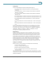
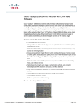
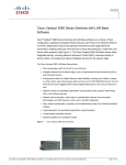
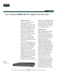
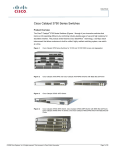
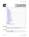
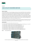
Data Sheet
Cisco Catalyst 2960 Series Switches
®
®
Cisco Catalyst 2960 Series Intelligent Ethernet Switches are a family of fixedconfiguration, standalone devices that provide desktop Fast Ethernet and Gigabit
Ethernet connectivity, enabling enhanced LAN services for entry-level enterprise,
mid-market, and branch office networks. The Catalyst 2960 Series offers integrated
security, including network admission control (NAC), advanced quality of service (QoS),
and resiliency to deliver intelligent services for the network edge.
The Cisco Catalyst 2960 Series offers:
Intelligent features at the network edge, such as sophisticated access control lists (ACLs)
and enhanced security
Dual-purpose uplinks for Gigabit Ethernet uplink flexibility, allowing use of either a copper
or a fiber uplink-each dual-purpose uplink port has one 10/100/1000 Ethernet port and one
Small Form-Factor Pluggable (SFP)-based Gigabit Ethernet port, with one port active
at a time
Network control and bandwidth optimization using advanced QoS, granular rate limiting,
ACLs, and multicast services
Network security through a wide range of authentication methods, data encryption
technologies, and network admission control based on users, ports, and MAC addresses
Easy network configuration, upgrades, and troubleshooting using Cisco Network
Assistant software
Auto-configuration for specialized applications using Smartports
Limited Lifetime Hardware Warranty
Figure 1.
Cisco Catalyst 2960 Series Switches
All contents are Copyright © 1992–2007 Cisco Systems, Inc. All rights reserved. This document is Cisco Public Information.
Page 1 of 14
Data Sheet
Configurations
The Cisco Catalyst 2960 Series comprises the following switches (Figure 1):
Cisco Catalyst 2960-8TC: 8 Ethernet 10/100 ports and 1 dual-purpose uplink port;
compact size
Cisco Catalyst 2960-24TT: 24 Ethernet 10/100 ports and 2 fixed Ethernet 10/100/1000
uplink ports; 1 rack unit (RU)
Cisco Catalyst 2960-48TT: 48 Ethernet 10/100 ports and 2 fixed Ethernet 10/100/1000
uplink ports; 1 RU
Cisco Catalyst 2960-24TC: 24 Ethernet 10/100 ports and 2 dual-purpose uplink ports; 1 RU
Cisco Catalyst 2960-48TC: 48 Ethernet 10/100 ports and 2 dual-purpose uplink ports; 1 RU
Cisco Catalyst 2960G-8TC: 8 Ethernet 10/100/1000 ports, 1 of which is dual-purpose;
compact size
Cisco Catalyst 2960G-24TC: 24 Ethernet 10/100/1000 ports, 4 of which are dual-purpose;
1 RU
Cisco Catalyst 2960G-48TC: 48 Ethernet 10/100/1000 ports, 4 of which are dual-purpose;
1 RU
The Cisco Catalyst 2960 Series software image is a rich suite of intelligent services, including
advanced QoS, rate limiting, ACLs, and IPv6 (future). The SFP-based Gigabit Ethernet ports
accommodate a range of SFP transceivers, including the Cisco 1000BASE-SX, 1000BASE-LX,
1000BASE-BX, 1000BASE-ZX, 100BASE-FX, 100BASE-LX, 100BASE-BX, and coarse
wavelength-division multiplexing (CWDM) SFP transceivers.
Gigabit Ethernet
At speeds of 1000 Mbps, Gigabit Ethernet provides the bandwidth to meet new and evolving
network demands, alleviate bottlenecks, and boost performance while increasing the return on
existing infrastructure investments. Today's workers are placing higher demands on networks,
running multiple concurrent applications. For example, a worker joins a team conference call
through an IP videoconference, sends a 10-MB spreadsheet to meeting participants, broadcasts
the latest marketing video for the team to evaluate, and queries the customer relationship
management (CRM) database for the latest real-time feedback. Meanwhile, a multigigabyte
system backup starts in the background and the latest virus updates are delivered to the client.
Intelligence in the Network
Networks of today are evolving to address four new developments at the network edge:
Increase in desktop computing power
Introduction of bandwidth-intensive applications
Expansion of highly sensitive data on the network
Presence of multiple device types, such as IP phones, WLAN access points,
and IP video cameras
These new demands contend for resources with existing mission-critical applications. As a result,
IT professionals must view the edge of the network as critical to effectively manage the delivery of
information and applications.
All contents are Copyright © 1992–2007 Cisco Systems, Inc. All rights reserved. This document is Cisco Public Information.
Page 2 of 14
Data Sheet
As companies increasingly rely on networks as their strategic business infrastructure, it is more
important than ever to ensure their high availability, security, scalability, and control. By adding
Cisco intelligent functions for LAN access, you can now deploy networkwide intelligent services
that consistently address these requirements from the desktop to the core and through the WAN.
With Cisco Catalyst Intelligent Ethernet switches, Cisco helps companies realize the full benefits
of adding intelligent services into their networks. Deploying capabilities that make the network
infrastructure highly available to accommodate time-critical needs, scalable to accommodate
growth, secure enough to protect confidential information, and capable of differentiating and
controlling traffic flows is critical to further optimizing network operations.
Enhanced Security
The wide range of security features that the Cisco Catalyst 2960 Series offers helps businesses
protect important information, keep unauthorized people off the network, guard privacy, and
maintain uninterrupted operation.
The Cisco Identity Based Networking Services (IBNS) solution provides authentication, access
control, and security policy administration to secure network connectivity and resources. Cisco
IBNS in the Cisco Catalyst 2960 Series prevents unauthorized access and helps ensure that users
get only their designated privileges. It provides the ability to dynamically administer granular levels
of network access. Using the 802.1x standard and the Cisco Secure Access Control Server (ACS),
users can be assigned a VLAN upon authentication, regardless of where they connect to the
network. This setup allows IT departments to enable strong security policies without compromising
user mobility, and with minimal administrative overhead.
To guard against denial-of-service (DoS) and other attacks, ACLs can be used to restrict access
to sensitive portions of the network by denying packets based on source and destination MAC
addresses, IP addresses, or TCP/User Datagram Protocol (UDP) ports. ACL lookups are done in
hardware, so forwarding performance is not compromised when implementing ACL-based security.
Port security can be used to limit access on an Ethernet port based on the MAC address of the
device to which it is connected. It also can be used to limit the total number of devices plugged into
a switch port, thereby protecting the switch from a MAC flooding attack as well as reducing the
risks of rogue wireless access points or hubs.
With Dynamic Host Configuration Protocol (DHCP) snooping, DHCP spoofing can be thwarted by
allowing only DHCP requests (but not responses) from untrusted user-facing ports. Additionally,
the DHCP Interface Tracker (Option 82) feature helps enable granular control over IP address
assignment by augmenting a host IP address request with the switch port ID.
The MAC Address Notification feature can be used to monitor the network and track users by
sending an alert to a management station so that network administrators know when and where
users entered the network. Secure Shell Protocol Version 2 (SSHv2) and Simple Network
Management Protocol Version 3 (SNMPv3) encrypt administrative and network-management
information, protecting the network from tampering or eavesdropping. TACACS+ or RADIUS
authentication enables centralized access control of switches and restricts unauthorized users
from altering the configurations. Alternatively, a local username and password database can be
configured on the switch itself. Fifteen levels of authorization on the switch console and two levels
on the Web-based management interface provide the ability to give different levels of configuration
capabilities to different administrators.
All contents are Copyright © 1992–2007 Cisco Systems, Inc. All rights reserved. This document is Cisco Public Information.
Page 3 of 14
Data Sheet
Availability and Scalability
The Cisco Catalyst 2960 Series is equipped with a large set of features that allow for network
scalability and higher availability through multicast filtering as well as a complete suite of Spanning
Tree Protocol enhancements aimed to maximize availability in a Layer 2 network.
Enhancements to the standard Spanning Tree Protocol, such as Per-VLAN Spanning Tree Plus
(PVST+), UplinkFast, and PortFast, help to maximize network uptime. PVST+ allows for Layer 2
load sharing on redundant links to efficiently use the extra capacity inherent in a redundant design.
UplinkFast, PortFast, and BackboneFast all greatly reduce the standard 30- to 60-second
Spanning Tree Protocol convergence time. Flexlink provides bidirectional, fast convergence in less
than 100 milliseconds. The Loopguard and bridge protocol data unit (BPDU) guard enhancements
provide Spanning Tree Protocol loop avoidance.
Advanced QoS
The Cisco Catalyst 2960 Series offers superior multilayer QoS features to help ensure that
network traffic is classified and prioritized, and that congestion is avoided in the best possible
manner. Configuration of QoS is greatly simplified through automatic QoS (Auto QoS), a feature
that detects Cisco IP phones and automatically configures the switch for the appropriate
classification and egress queuing. This optimizes traffic prioritization and network availability
without the challenge of a complex configuration.
The Cisco Catalyst 2960 Series can classify, reclassify, police, mark, queue, and schedule
incoming packets and can queue and schedule packets at egress. Packet classification allows
the network elements to discriminate between various traffic flows and enforce policies based on
Layer 2 and Layer 3 QoS fields.
To implement QoS, the Cisco Catalyst 2960 Series Switch first identifies traffic flows or packet
groups, then classifies or reclassifies these groups using the differentiated services code point
(DSCP) field or the 802.1p class of service (CoS) field. Classification and reclassification can be
based on criteria as specific as the source or destination IP address, source or destination MAC
address, or the Layer 4 TCP or UDP port. At the ingress, the Catalyst 2960 Series also polices to
determine whether a packet is in or out of profile, marks to change the classification label, passes
through or drops out of profile packets, and queues packets based on classification. Control-plane
and data-plane ACLs are supported on all ports to help ensure proper treatment on a per-packet
basis.
The Cisco Catalyst 2960 Series supports four egress queues per port, giving network
administrators more control in assigning priorities for the various applications on the LAN. At
egress, the switch performs congestion control and scheduling, the algorithm or process that
determines the order in which queues are processed. The Catalyst 2960 Series Switch supports
Shaped Round Robin (SRR) and strict priority queuing. The SRR algorithm helps ensure
differential prioritization.
These QoS features allow network administrators to prioritize mission-critical and bandwidthintensive traffic, such as enterprise resource planning (ERP), voice (IP telephony traffic), and
computer-aided design and manufacturing (CAD/CAM), over applications such as FTP or e-mail.
For example, it would be undesirable to have a large file download destined to one port on a
switch increase latency in voice traffic destined to another port on this switch. This condition is
avoided by ensuring that voice traffic is properly classified and prioritized throughout the network.
Other applications, such as Web browsing, can be handled on a lower-priority basis.
All contents are Copyright © 1992–2007 Cisco Systems, Inc. All rights reserved. This document is Cisco Public Information.
Page 4 of 14
Data Sheet
The Cisco Catalyst 2960 Series can perform rate limiting through its support of the Cisco
committed information rate (CIR) function. Through CIR, bandwidth can be guaranteed in
increments as small as 1 Mbps. Bandwidth can be allocated based on several criteria, including
MAC source address, MAC destination address, IP source address, IP destination address, and
TCP or UDP port number. Bandwidth allocation is essential when network environments require
service-level agreements or when it is necessary to control the bandwidth given to certain users.
Management
The new Express Setup feature simplifies the initial configuration of a switch. Now you can set up
the switch through a Web browser, eliminating the need for terminal-emulation programs and the
command-line interface (CLI). Express Setup reduces the cost of deployment by helping lessskilled personnel quickly and easily set up switches.
Cisco Network Assistant is a PC-based network-management application optimized for LANs
with up to 250 users. Cisco Network Assistant offers centralized management of Cisco switches,
routers, and WLAN access points. It supports a wide range of Cisco Catalyst intelligent switches
from Cisco Catalyst 2960 through Cisco Catalyst 4506. Through a user-friendly GUI, users can
configure and manage a wide array of switch functions and start the device manager of Cisco
routers and Cisco wireless access points. A few mouse clicks enable the Cisco recommended
security, availability, and QoS features without the need to consult a detailed design guide.
The Security wizard automatically restricts unauthorized access to servers with sensitive data.
Smartports and wizards save time for network administrators, reduce human errors, and help
ensure that the configuration of the switch is optimized for these applications. Available at no
cost, Cisco Network Assistant can be downloaded from the Cisco Website.
In addition to Cisco Network Assistant, Cisco Catalyst 2960 Series switches provide for extensive
management using SNMP network-management platforms such as CiscoWorks LAN Management
Solution (LMS). LMS is a suite of powerful management tools that simplify the configuration,
administration, monitoring and troubleshooting of Cisco networks. It integrates these capabilities
into a world-class solution for improving the accuracy and efficiency of your operations staff, while
increasing the overall availability of your network. LMS supports over 400 different device types
providing:
Network discovery, topology views, end-station tracking and VLAN management
Real-time network fault analysis with easy-to-deploy device specific best-practice templates
Hardware and software inventory management, centralized configuration tools,
and Syslog monitoring
Network response time and availability monitoring and tracking
Real-time device, link, and port traffic management, analysis, and reporting
Table 1 gives the features and benefits of the Cisco Catalyst 2960 Series. Table 2 gives the
hardware specifications, and Table 3 gives the power specifications. Table 4 lists the management
and standards support, and Table 5 provides the safety and compliance information.
All contents are Copyright © 1992–2007 Cisco Systems, Inc. All rights reserved. This document is Cisco Public Information.
Page 5 of 14
Data Sheet
Table 1.
Features and Benefits of Cisco Catalyst 2960 Series
Feature
Benefit
Ease of Use and
Deployment
Express Setup simplifies initial configuration with a Web browser, eliminating the need for more
complex terminal emulation programs and CLI knowledge.
DHCP autoconfiguration of multiple switches through a boot server eases switch deployment.
Automatic QoS (Auto QoS) simplifies QoS configuration in voice-over-IP (VoIP) networks by
issuing interface and global switch commands to detect Cisco IP phones, classify traffic, and
enable egress queue configuration.
Autosensing on each 10/100 port detects the speed of the attached device and automatically
configures the port for 10- or 100-Mbps operation, easing switch deployment in mixed 10- and
100-Mbps environments.
Autonegotiating on all ports automatically selects half- or full-duplex transmission mode
to optimize bandwidth.
Dynamic Trunking Protocol (DTP) helps enable dynamic trunk configuration across all switch
ports.
®
Port Aggregation Protocol (PAgP) automates the creation of Cisco Fast EtherChannel groups
or Gigabit EtherChannel groups to link to another switch, router, or server.
Link Aggregation Control Protocol (LACP) allows the creation of Ethernet channeling with
devices that conform to IEEE 802.3ad. This feature is similar to Cisco EtherChannel
technology and PAgP.
DHCP Server enables a convenient deployment option for the assignment of IP addresses in
networks that do not have without a dedicated DHCP server.
DHCP Relay allows a DHCP relay agent to broadcast DHCP requests to the network DHCP
server.
1000BASE-SX, 1000BASE-LX/LH, 1000BASE-ZX, 1000BASE-BX, 100BASE-FX, 100BASELX, 100BASE-BX, and coarse wavelength-division multiplexing (CWDM) physical interface
support through a field-replaceable SFP module provides unprecedented flexibility in switch
deployment.
The default configuration stored in flash memory ensures that the switch can be quickly
connected to the network and can pass traffic with minimal user intervention.
Automatic medium-dependent interface crossover (Auto-MDIX) automatically adjusts transmit
and receive pairs if an incorrect cable type (crossover or straight-through) is installed on a
copper port.
Time-domain reflectometer (TDR) to diagnose and resolve cabling problems on copper ports.
Availability and Scalability
Superior
Redundancy for
Fault Backup
Cisco UplinkFast and BackboneFast technologies help ensure quick failover recovery,
enhancing overall network stability and reliability.
IEEE 802.1w Rapid Spanning Tree Protocol provides rapid spanning-tree convergence
independent of spanning-tree timers and the benefit of distributed processing.
Per-VLAN Rapid Spanning Tree Plus (PVRST+) allows rapid spanning-tree reconvergence
on a per-VLAN spanning-tree basis, without requiring the implementation of spanning-tree
instances.
Command-switch redundancy enabled in Cisco Network Assistant software allows designation
of a backup command switch that takes over if the primary command switch fails.
Unidirectional Link Detection Protocol (UDLD) and Aggressive UDLD allow unidirectional links
to be detected and disabled to avoid problems such as spanning-tree loops.
Switch port autorecovery (errdisable) automatically attempts to re-enable a link that is disabled
because of a network error.
Cisco Redundant Power System 675 (RPS 675) support provides superior internal powersource redundancy for up to six Cisco networking devices, resulting in improved fault tolerance
and network uptime.
Bandwidth aggregation up to 8 Gbps through Cisco Gigabit EtherChannel technology and up to
800 Mbps through Cisco Fast EtherChannel technology enhances fault tolerance and offers
higher-speed aggregated bandwidth between switches and to routers and individual servers.
Integrated Cisco
IOS® Software
Features for
Bandwidth
Optimization
Per-port broadcast, multicast, and unicast storm control prevents faulty end stations from
degrading overall systems performance.
IEEE 802.1d Spanning Tree Protocol support for redundant backbone connections and loopfree networks simplifies network configuration and improves fault tolerance.
PVST+ allows for Layer 2 load sharing on redundant links to efficiently use the extra capacity
inherent in a redundant design.
IEEE 802.1s Multiple Spanning Tree Protocol allows a spanning-tree instance per VLAN,
enabling Layer 2 load sharing on redundant links.
Egress committed rate (ECR) guarantee provides load balancing and redundancy.
Local Proxy Address Resolution Protocol (ARP) works in conjunction with Private VLAN Edge
to minimize broadcasts and maximize available bandwidth.
VLAN1 minimization allows VLAN1 to be disabled on any individual VLAN trunk link.
VLAN Trunking Protocol (VTP) pruning limits bandwidth consumption on VTP trunks by
flooding broadcast traffic only on trunk links required to reach the destination devices.
All contents are Copyright © 1992–2007 Cisco Systems, Inc. All rights reserved. This document is Cisco Public Information.
Page 6 of 14
Data Sheet
Feature
Benefit
Internet Group Management Protocol (IGMP) version 3 snooping provides fast client joins and
leaves of multicast streams and limits bandwidth-intensive video traffic to only the requestors.
IGMP filtering provides multicast authentication by filtering out no subscribers and limits the
number of concurrent multicast streams available per port.
Multicast VLAN registration (MVR) continuously sends multicast streams in a multicast VLAN
while isolating e streams from subscriber VLANs for bandwidth and security reasons.
QoS and Control
Advanced QoS
Standard 802.1p CoS and DSCP field classification are provided, using marking and
reclassification on a per-packet basis by source and destination IP address, source and
destination MAC address, or Layer 4 TCP or UDP port number.
Cisco control-plane and data-plane QoS ACLs on all ports help ensure proper marking on a
per-packet basis.
Four egress queues per port enable differentiated management of up to four traffic types
across the stack.
SRR scheduling ensures differential prioritization of packet flows by intelligently servicing the
ingress and egress queues.
Weighted tail drop (WTD) provides congestion avoidance at the ingress and egress queues
before a disruption occurs.
Strict priority queuing guarantees that the highest-priority packets are serviced ahead of all
other traffic.
There is no performance penalty for highly granular QoS functions.
Granular Rate
Limiting
The Cisco CIR function guarantees bandwidth in increments as small as 1 Mbps.
Rate limiting is provided based on source and destination IP address, source and destination
MAC address, Layer 4 TCP and UDP information, or any combination of these fields, using
QoS ACLs (IP ACLs or MAC ACLs), class maps, and policy maps.
Asynchronous data flows upstream and downstream from the end station or on the uplink are
easily managed using ingress policing and egress shaping.
Up to 64 aggregate or individual polices are available per Fast Ethernet or Gigabit Ethernet
port.
Security
Networkwide
Security Features
IEEE 802.1x allows dynamic, port-based security, providing user authentication.
IEEE 802.1x with VLAN assignment allows a dynamic VLAN assignment for a specific
user regardless of where the user is connected.
IEEE 802.1x with voice VLAN permits an IP phone to access the voice VLAN irrespective
of the authorized or unauthorized state of the port.
IEEE 802.1x and port security are provided to authenticate the port and manage network
access for all MAC addresses, including those of the client.
IEEE 802.1x with Guest VLAN allows guests without 802.1x clients to have limited network
access on the guest VLAN.
Port-based ACLs for Layer 2 interfaces allow application of security policies on individual
switch ports.
Unicast MAC filtering prevents the forwarding of any type of packet with a matching
MAC address.
Unknown unicast and multicast port blocking allows tight control by filtering packets that the
switch has not already learned how to forward.
SSHv2 and SNMPv3 provide network security by encrypting administrator traffic during Telnet
and SNMP sessions. SSHv2 and the cryptographic version of SNMPv3 require a special
cryptographic software image because of U.S. export restrictions.
Bidirectional data support on the Switched Port Analyzer (SPAN) port allows the Cisco Secure
intrusion detection system (IDS) to take action when an intruder is detected.
TACACS+ and RADIUS authentication enable centralized control of the switch and restrict
unauthorized users from altering the configuration.
MAC address notification allows administrators to be notified of users added to or removed
from the network.
DHCP snooping allows administrators to ensure consistent mapping of IP to MAC addresses.
This can be used to prevent attacks that attempt to poison the DHCP binding database, and to
rate-limit the amount of DHCP traffic that enters a switch port.
DHCP Interface Tracker (Option 82) feature augments a host IP address request with the
switch port ID.
Port security secures the access to an access or trunk port based on MAC address.
After a specific timeframe, the aging feature removes the MAC address from the switch to
allow another device to connect to the same port.
Trusted Boundary provides the ability to trust the QoS priority settings if an IP phone is present
and to disable the trust setting if the IP phone is removed, thereby preventing a malicious user
from overriding prioritization policies in the network.
Multilevel security on console access prevents unauthorized users from altering the switch
configuration.
All contents are Copyright © 1992–2007 Cisco Systems, Inc. All rights reserved. This document is Cisco Public Information.
Page 7 of 14
Data Sheet
Feature
Benefit
The user-selectable address-learning mode simplifies configuration and enhances security.
BPDU Guard shuts down Spanning Tree Protocol PortFast-enabled interfaces when BPDU's
are received to avoid accidental topology loops.
Spanning-Tree Root Guard (STRG) prevents edge devices not in the network administrator's
control from becoming Spanning Tree Protocol root nodes.
IGMP filtering provides multicast authentication by filtering out no subscribers and limits the
number of concurrent multicast streams available per port.
Dynamic VLAN assignment is supported through implementation of VLAN Membership Policy
Server (VMPS) client functions to provide flexibility in assigning ports to VLANs. Dynamic
VLAN helps enable the fast assignment of IP addresses.
Cisco Network Assistant software security wizards ease the deployment of security features for
restricting user access to a server as well as to a portion of or the entire network.
Up to 512 (Aces) are supported, with two profiles: Security (384 Security ACL entries and
128 QoS policies), and QoS (128 Security ACL entries and 384 QoS polices).
Manageability
Superior
Manageability
Cisco IOS CLI support provides a common user interface and command set with all
Cisco routers and Cisco Catalyst desktop switches.
Cisco Service Assurance Agent (SAA) support facilitates service-level management throughout
the LAN.
Switching Database Manager templates for security and QoS allow administrators to easily
adjust memory allocation to the desired features based on deployment-specific requirements.
VLAN trunks can be created from any port using standards-based 802.1q tagging.
Up to 255 VLANs per switch or stack and up to 128 spanning-tree instances per switch
are supported.
Four thousand VLAN IDs are supported.
Voice VLAN simplifies telephony installations by keeping voice traffic on a separate VLAN
for easier administration and troubleshooting.
Cisco VTP supports dynamic VLANs and dynamic trunk configuration across all switches.
IGMPv3 snooping provides fast client joins and leaves of multicast streams and limits
bandwidth-intensive video traffic to only the requestors.
Remote SPAN (RSPAN) allows administrators to remotely monitor ports in a Layer 2
switch network from any other switch in the same network.
For enhanced traffic management, monitoring, and analysis, the Embedded Remote
Monitoring (RMON) software agent supports four RMON groups (history, statistics, alarms, and
events).
Layer 2 trace route eases troubleshooting by identifying the physical path that a packet takes
from source to destination.
All RMON groups are supported through a SPAN port, which permits traffic monitoring of a
single port, a group of ports, or the entire stack from a single network analyzer or RMON probe.
Domain Name System (DNS) provides IP address resolution with user-defined device names.
Trivial File Transfer Protocol (TFTP) reduces the cost of administering software upgrades by
downloading from a centralized location.
Network Timing Protocol (NTP) provides an accurate and consistent timestamp to all intranet
switches.
Multifunction LEDs per port for port status; half-duplex and full-duplex mode; and 10BASE-T,
100BASE-TX, and 1000BASE-T indication as well as switch-level status LEDs for system,
redundant power supply, and bandwidth use provide a comprehensive and convenient visual
management system.
Cisco Network
Assistant
Software
Cisco Network Assistant is a no-charge, Windows-based application that simplifies the
administration of networks of up to 250 users. It supports a wide range of Cisco Catalyst
intelligent switches. With Cisco Network Assistant, users can manage Cisco Catalyst switches
and launch the device managers of Cisco integrated services routers and Cisco Aironet WLAN
access points.
The easy-to-use graphical interface provides both a topology map and front-panel view of the
cluster and stacks.
Configuration wizards need just a few user inputs to automatically configure the switch to
optimally handle different types of traffic: voice, video, multicast, and high-priority data.
A security wizard is provided to restrict unauthorized access to applications, servers, and
networks.
Upgrading the Cisco IOS Software on Cisco Catalyst switches is a simple matter of pointing
and clicking, with one-click upgrades.
Cisco Network Assistant supports multilayer feature configurations such as routing protocols,
ACLs, and QoS parameters.
Multidevice and multiport configuration capabilities allow administrators to save time by
configuring features across multiple switches and ports simultaneously.
The user-personalized interface allows modification of polling intervals, table views,
and other settings.
Alarm notification provides automated e-mail notification of network errors and alarm
All contents are Copyright © 1992–2007 Cisco Systems, Inc. All rights reserved. This document is Cisco Public Information.
Page 8 of 14
Data Sheet
Feature
Benefit
thresholds.
Cisco Express
Setup
Express Setup simplifies initial configuration of a switch through a Web browser, eliminating
the need for terminal emulation programs and CLI knowledge.
The Web interface helps less-skilled personnel quickly and simply set up switches, thereby
reducing the cost of deployment.
CiscoWorks
Support
CiscoWorks network-management software provides management capabilities on a per-port
and per-switch basis, providing a common management interface for Cisco routers, switches,
and hubs.
SNMPv1, v2c, and v3 and Telnet interface support delivers comprehensive in-band
management, and a CLI-based management console provides detailed out-of-band
management.
Cisco Discovery Protocol Versions 1 and 2 help enable a CiscoWorks network-management
station for automatic switch discovery.
The CiscoWorks LAN Management Solution supports the Cisco Catalyst 2960 Series.
Table 2.
Cisco Catalyst 2960 Series Switch Hardware
Description
Performance
Specification
16 Gbps switching fabric (Catalyst 2960-8TC, Catalyst 2960-24TT, Catalyst 2960-24TC, Catalyst
2960-48TT, Catalyst 2960-48TC)
32 Gbps switching fabric (Catalyst 2960G-8TC, Catalyst 2960G-24TC, Catalyst 2960G-48TC)
Forwarding rate based on 64-byte packets:
Catalyst 2960-8TC: 2.7 Mpps
Catalyst 2960-24TT: 6.5 Mpps
Catalyst 2960-24TC: 6.5 Mpps
Catalyst 2960-48TT: 10.1 Mpps
Catalyst 2960-48TC: 10.1 Mpps
Catalyst 2960G-8TC: 11.9 Mpps
Catalyst 2960G-24TC: 35.7 Mpps
Catalyst 2960G-48TC: 39.0 Mpps
64 MB DRAM
32 MB flash memory
Configurable up to 8000 MAC addresses
Configurable up to 255 IGMP groups
Configurable maximum transmission unit (MTU) of up to 9000 bytes, with a maximum Ethernet
frame size of 9018 bytes (Jumbo frames) for bridging on Gigabit Ethernet ports, and up to 1998
bytes for bridging of Multiprotocol Label Switching (MPLS) tagged frames on both 10/100 and
10/100/1000 ports
Connectors
and Cabling
10BASE-T ports: RJ-45 connectors, 2-pair Category 3, 4, or 5 unshielded twisted-pair (UTP)
cabling
100BASE-TX ports: RJ-45 connectors, 2-pair Category 5 UTP cabling
1000BASE-T ports: RJ-45 connectors, 4-pair Category 5 UTP cabling
1000BASE-T SFP-based ports: RJ-45 connectors, 4-pair Category 5 UTP cabling
1000BASE-SX, -LX/LH, -ZX, -BX and CWDM SFP-based ports: LC fiber connectors
(single/multimode fiber)
100BASE-LX, -BX, -FX: LC fiber connectors (single/multimode fiber).
Power
Connectors
Customers can provide power to a switch by using either the internal power supply or the Cisco
RPS 675. The connectors are located at the back of the switch.
Note: The Catalyst 2960-8TC and Catalyst 2960G-8TC do not have RPS ports.
Internal-Power-Supply Connector
The internal power supply is an autoranging unit.
The internal power supply supports input voltages between 100 and 240VAC.
Use the supplied AC power cord to connect the AC power connector to an AC power outlet.
Cisco RPS Connector
The connector offers connection for an optional Cisco RPS 675 that uses AC input and supplies
DC output to the switch.
The connector offers a 675W redundant power system that supports up to six external network
devices and provides power to one failed device at a time.
The connector automatically senses when the internal power supply of a connected device fails
and provides power to the failed device, preventing loss of network traffic.
Only the Cisco RPS 675 (model PWR675-AC-RPS-N1=) should be attached to the redundantpower-system receptacle.
Indicators
Per-port status: Link integrity, disabled, activity, speed, full-duplex
All contents are Copyright © 1992–2007 Cisco Systems, Inc. All rights reserved. This document is Cisco Public Information.
Page 9 of 14
Data Sheet
Description
Specification
System status: System, RPS, link status, link duplex, link speed
Dimensions
(H x W x D)
Cisco Catalyst 2960-8TC: 1.73 x 10.6 x 6.4 in. (4.4 x 27 x 16.3 cm)
Cisco Catalyst 2960-24TT: 1.73 x 17.5 x 9.3 in. (4.4 x 44.5 x 23.6 cm)
Cisco Catalyst 2960-48TT: 1.73 x 17.5 x 9.3 in. (4.4 x 44.5 x 23.6 cm)
Cisco Catalyst 2960-24TC: 1.73 x 17.5 x 9.3 in. (4.4 x 44.5 x 23.6 cm)
Cisco Catalyst 2960-48TC: 1.73 x 17.5 x 9.3 in. (4.4 x 44.5 x 23.6 cm)
Cisco Catalyst 2960G-8TC: 1.73 x 10.6 x 8.1 in. (4.4 x 27 x 20.5 cm)
Cisco Catalyst 2960G-24TC: 1.73 x 17.5 x 12.9 in. (4.4 x 44.5 x 32.8 cm)
Cisco Catalyst 2960G-48TC: 1.73 x 17.5 x 12.9 in. (4.4 x 44.5 x 32.8 cm)
Weight
Cisco Catalyst 2960-8TC: 3 lb (1.4 kg)
Cisco Catalyst 2960-24TT: 8 lb (3.6 kg)
Cisco Catalyst 2960-48TT: 8 lb (3.6 kg)
Cisco Catalyst 2960-24TC: 8 lb (3.6 kg)
Cisco Catalyst 2960-48TC: 8 lb (3.6 kg)
Cisco Catalyst 2960G-8TC: 3 lb (1.4 kg)
Cisco Catalyst 2960G-24TC: 10 lb (4.5 kg)
Cisco Catalyst 2960G-48TC: 12 lb (5.4 kg)
Environmental
Ranges
Operating temperature: 32 to 113°F (0 to 45°C)
Storage temperature: –13 to 158°F (–25 to 70°C)
Operating relative humidity: 10 to 85% (noncondensing)
Operating altitude: Up to 10,000 ft (3049m)
Storage altitude: Up to 15,000 ft (4573m)
Acoustic Noise
ISO 7779: Bystander position operating to an ambient temperature of 25°C
Cisco Catalyst 2960-8TC: 0 dBa (no fan)
Cisco Catalyst 2960-24TT: 40 dBa
Cisco Catalyst 2960-48TT: 40 dBa
Cisco Catalyst 2960-24TC: 40 dBa
Cisco Catalyst 2960-48TC: 40 dBa
Cisco Catalyst 2960G-8TC: 0 dBa (no fan)
Cisco Catalyst 2960G-24TC: 41 dBa
Cisco Catalyst 2960G-48TC: 43 dBa
Mean Time
Between Failure
(MTBF)
Cisco Catalyst 2960-8TC: 530,877 hrs
Cisco Catalyst 2960-24TT: 282,416 hrs
Cisco Catalyst 2960-48TT: 245,213 hrs
Cisco Catalyst 2960-24TC: 280,271 hrs
Cisco Catalyst 2960-48TC: 243,595 hrs
Cisco Catalyst 2960G-8TC: 465,567 hrs
Cisco Catalyst 2960G-24TC: 219,629 hrs
Cisco Catalyst 2960G-48TC: 167,606 hrs
Table 3.
Power Specifications for Cisco Catalyst 2960 Series Switch
Description
Maximum Power
Consumption
Specification
20W (Cisco Catalyst 2960-8TC)
30W (Cisco Catalyst 2960-24TT and Catalyst 2960-24TC)
45W (Cisco Catalyst 2960-48TT and Catalyst 2960-48TC)
30W (Cisco Catalyst 2960G-8TC)
75W (Cisco Catalyst 2960G-24TC)
140W (Cisco Catalyst 2960G-48TC)
AC Input Voltage
and Current
100-240VAC (autoranging), 0.5-0.25A, 50-60 H z ( Cisco Catalyst 2960-8T C)
100-240V AC (autoranging) , 0.8-0.4A, 50-60 H z ( Cisco Catalyst 2960G -8T C)
100-240V AC (autoranging) , 1.3–0.8A, 50–60 H z ( Cisco Catalyst 2960-24T T
and Catalyst 2960-24T C and Catalyst 2960-48T T and Catalyst 2960-48T C)
100-240V AC (autoranging) , 3.0–1.5A, 50–60 H z ( Cisco Catalyst 2960G -24T C
and Catalyst 2960G -48T C)
Power Rating
Cisco Catalyst 2960-8TC: 0.035 kVA
Cisco Catalyst 2960-24TT: 0.05kVA
Cisco Catalyst 2960-48TT: 0.075kVA
All contents are Copyright © 1992–2007 Cisco Systems, Inc. All rights reserved. This document is Cisco Public Information.
Page 10 of 14
Data Sheet
Description
Specification
Cisco Catalyst 2960-24TC: 0.05kVA
Cisco Catalyst 2960-48TC: 0.075kVA
Cisco Catalyst 2960G-8TC: 0.05 kVA
Cisco Catalyst 2960G-24TC: 0.075kVA
Cisco Catalyst 2960G-48TC: 0.140kVA
DC Input Voltages
(RPS Input)
(No RPS input for Cisco Catalyst 2960-8TC and Catalyst 2960G-8TC)
Cisco Catalyst 2960-24TT: +12V at 5A
Cisco Catalyst 2960-48TT: +12V at 5A
Cisco Catalyst 2960-24TC: +12V at 5A
Cisco Catalyst 2960-48TC: +12V at 5A
Cisco Catalyst 2960G-24TC: +12V at 10.5A
Cisco Catalyst 2960G-48TC: +12V at 10.5A
Table 4.
Management and Standards Support for Cisco Catalyst 2960 Series Switch
Description
Management
Specification
BRIDGE-MIB
CISCO-VTP-MIB
CISCO-CDP-MIB
ENTITY-MIB
CISCO-CLUSTER-MIB
ETHERLIKE-MIB
CISCO-CONFIG-MAN-MIB
IF-MIB
CISCO-ENVMON-MIB
OLD-CISCO-CHASSIS-MIB
CISCO-FLASH-MIB
OLD-CISCO-FLASH-MIB
CISCO-FTP-CLIENT-MIB
OLD-CISCO-INTERFACES-MIB
CISCO-IMAGE-MIB
OLD-CISCO-SYS-MIB
CISCO-IP-STAT-MIB
RFC1213-MIB
CISCO-L2L3-INTERFACE-CONFIG-MIB
RFC1253-MIB
CISCO-MAC-NOTIFICATION-MIB
RMON-MIB
CISCO-MEMORY-POOL-MIB
RMON2-MIB
CISCO-PAGP-MIB
SNMP-FRAMEWORK-MIB
CISCO-PING-MIB
SNMP-MPD-MIB
CISCO-PROCESS-MIB
SNMP-NOTIFICATION-MIB
CISCO-RTTMON-MIB
SNMP-TARGET-MIB
CISCO-STP-EXTENSIONS-MIB
SNMPv2-MIB
CISCO-SYSLOG-MIB
TCP-MIB
CISCO-VLAN-IFTABLE-RELATIONSHIP-MIB
UDP-MIB
CISCO-VLAN-MEMBERSHIP-MIB
Standards
IEEE 802.1s
100BASE-BX (SFP)
IEEE 802.1w
100BASE-FX (SFP)
IEEE 802.1x
100BASE-LX (SFP)
IEEE 802.3ad
1000BASE-BX (SFP)
IEEE 802.3ah (100BASE-X single/multimode
fiber only)
1000BASE-SX
IEEE 802.3x full duplex on 10BASE-T,
100BASE-TX, and 1000BASE-T ports
1000BASE-ZX
IEEE 802.1D Spanning Tree Protocol
IEEE 802.1p CoS Prioritization
IEEE 802.1Q VLAN
IEEE 802.3 10BASE-T specification
IEEE 802.3u 100BASE-TX specification
IEEE 802.3ab 1000BASE-T specification
IEEE 802.3z 1000BASE-X specification
1000BASE-LX/LH
1000BASE-CWDM SFP 1470 nm
1000BASE-CWDM SFP 1490 nm
1000BASE-CWDM SFP 1510 nm
1000BASE-CWDM SFP 1530 nm
1000BASE-CWDM SFP 1550 nm
1000BASE-CWDM SFP 1570 nm
1000BASE-CWDM SFP 1590 nm
1000BASE-CWDM SFP 1610 nm
RMON I and II standards
SNMPv1, SNMPv2c, and SNMPv3
All contents are Copyright © 1992–2007 Cisco Systems, Inc. All rights reserved. This document is Cisco Public Information.
Page 11 of 14
Data Sheet
Table 5.
Safety and Compliance
Description
Specification
Safety Certifications
UL 60950-1, First Edition
CUL to CAN/CSA 22.2 No. 60950-1, First Edition
TUV/GS to EN 60950-1, First Edition
CB to IEC 60950-1 with all country deviations
AS/NZS 60950-1, First Edition
CE Marking
NOM (through partners and distributors)
Electromagnetic
Compatibility
Certifications
FCC Part 15 Class A
EN 55022 Class A (CISPR22)
EN 55024 (CISPR24)
AS/NZS CISPR22 Class A
CE
CNS13438 Class A
MIC
GOST
China EMC Certifications
Telco
Common Language Equipment Identifier (CLEI) code
Warranty
Limited lifetime warranty
Service and Support
Cisco is committed to minimizing total cost of ownership (TCO). Its portfolio of technical support
services help ensure that its products operate efficiently, remain highly available, and benefit from
the most up-to-date system software. The services and support programs described in Table 6 are
available as part of the Cisco Desktop Switching Service and Support solution, and are available
directly from Cisco and through resellers.
Table 6.
Cisco Services and Support Programs
Service and Support
Cisco Total Implementation
Solutions (TIS), available direct
from Cisco
Cisco Packaged TIS, available
through resellers
Cisco SMARTnet® and
SMARTnet Onsite support,
available direct from Cisco
Cisco Packaged SMARTnet
support program, available
through resellers
Cisco SMB Support Assistant
Features
Project management
Site survey, configuration, and deployment
Installation, text, and cutover
Training
Major moves, adds, and changes
Design review and product staging
24-hour access to software updates
Web access to technical repositories
Telephone support through the Cisco
Technical Assistance Center (TAC)
Advance replacement of hardware parts
All contents are Copyright © 1992–2007 Cisco Systems, Inc. All rights reserved. This document is Cisco Public Information.
Benefits
Supplements existing
staff
Helps ensure that
functions meet needs
Mitigates risk
Helps enable proactive or
expedited issue resolution
Lowers TCO by taking
advantage of Cisco
expertise and knowledge
Helps minimize network
downtime
Page 12 of 14
Data Sheet
Ordering Information
Table 7 gives ordering information for Cisco Catalyst 2960 Series switches.
Table 7.
Ordering Information for Cisco Catalyst 2960 Series Switches
Part Numbers
WS-C2960-8TC-L
Description
8 Ethernet 10/100 ports and 1 dual-purpose uplink (dual-purpose uplink port has one
10/100/1000 Ethernet port and 1 SFP-based Gigabit Ethernet port, 1 port active)
Compact size with no fan; magnet included
LAN Base Image installed
WS-C2960-24TT-L
24 Ethernet 10/100 ports and two 10/100/1000TX uplinks
1 RU fixed-configuration
LAN Base Image installed
WS-C2960-48TT-L
48 Ethernet 10/100 ports and two 10/100/1000TX uplinks
1 RU fixed-configuration
LAN Base Image installed
WS-C2960-24TC-L
24 Ethernet 10/100 ports and 2 dual-purpose uplinks (each dual-purpose uplink port
has one 10/100/1000 Ethernet port and 1 SFP-based Gigabit Ethernet port, 1 port
active)
1 RU fixed-configuration
LAN Base Image installed
WS-C2960-48TC-L
48 Ethernet 10/100 ports and 2 dual-purpose uplinks (each dual-purpose uplink port
has one 10/100/1000 Ethernet port and 1 SFP-based Gigabit Ethernet port, 1 port
active)
1 RU fixed-configuration
LAN Base Image installed
WS-C2960G-8TC-L
7 Ethernet 10/100/1000 ports and 1 dual-purpose uplink (dual-purpose uplink port has
one 10/100/1000 Ethernet port and 1 SFP-based Gigabit Ethernet port, 1 port active)
Compact size with no fan; magnet included
LAN Base Image installed
WS-C2960G-24TC-L
20 Ethernet 10/100/1000 ports and 4 dual-purpose uplinks (each dual-purpose uplink
port has one 10/100/1000 Ethernet port and 1 SFP-based Gigabit Ethernet port, 1 port
active)
1 RU fixed-configuration
LAN Base Image installed
WS-C2960G-48TC-L
44 Ethernet 10/100/1000 ports and 4 dual-purpose uplinks (each dual-purpose uplink
port has one 10/100/1000 Ethernet port and 1 SFP-based Gigabit Ethernet port, 1 port
active)
1 RU fixed-configuration, multilayer switch
LAN Base Image installed
PWR675-AC-RPS-N1=
Cisco RPS 675 with one connector cable
CAB-RPS-1614=
1.2m cable for Cisco RPS 675 to external device connection
CBLGRD-C2960-8TC=
Cable guard for the Cisco Catalyst 2960-8TC compact switch
CBLGRD-C2960G-8TC=
Cable guard for the Cisco Catalyst 2960G-8TC compact switch
RCKMNT-19-CMPCT=
Rack-mount for the Cisco Catalyst 2960-8TC and Catalyst 2960G-8TC compact switches
RCKMNT-1RU=
Spare rack-mount kit for the Cisco Catalyst 2960 Series
RCKMNT-REC-1RU=
1 RU recessed rack-mount kit for the Cisco Catalyst 2960 Series
GLC-LH-SM=
1000BASE-LX/LH SFP transceiver module for MMF and SMF, 1300-nm wavelength
GLC-SX-MM=
1000BASE-SX SFP transceiver module for MMF, 850-nm wavelength
GLC-ZX-SM=
1000BASE-ZX SFP transceiver module for SMF, 1550-nm wavelength
GLC-T=
1000BASE-T SFP transceiver module for Category 5 copper wire
Not supported on the Cisco Catalyst 2960-8TC and Catalyst 2960G-8TC
compact switches
GLC-BX-D=
1000BASE-BX10 SFP transceiver module for single strand SMF, 1490-nm TX / 1310-nm
RX wavelength
GLC-BX-U=
1000BASE-BX10 SFP transceiver module for single strand SMF, 1310-nm TX / 1490-nm
All contents are Copyright © 1992–2007 Cisco Systems, Inc. All rights reserved. This document is Cisco Public Information.
Page 13 of 14
Data Sheet
Part Numbers
Description
RX wavelength
GLC-GE-100FX=
100BASE-FX SFP module for Gigabit Ethernet ports, 1310-nm wavelength, 2 km over MMF
Not supported on the Cisco Catalyst 2960-8TC and Catalyst 2960G-8TC compact switches
GLC-FE-100FX=
100BASE-FX SFP module for 100-Mb ports, 1310-nm wavelength, 2 km over MMF
GLC-FE-100LX=
100BASE-FX SFP module for 100-Mb ports, 1310-nm wavelength, 10 km over SMF
GLC-FE-100BX-D=
100BASE-BX10-D SFP module for 100-Mb ports, 1550-nm TX /1310-nm RX wavelength,
10 km over single-strand SMF
GLC-FE-100BX-U=
100BASE-BX10-U SFP module for 100-Mb ports, 1310-nm TX/1550-nm RX wavelength,
10 km over single-strand SMF
CWDM-SFP-1470=
Cisco CWDM SFP 1470 nm; Gigabit Ethernet and 1G/2G FC (gray)
CWDM-SFP-1490=
Cisco CWDM SFP, 1490 nm; Gigabit Ethernet and 1G/2G FC (violet)
CWDM-SFP-1510=
Cisco CWDM SFP, 1510 nm; Gigabit Ethernet and 1G/2G FC (blue)
CWDM-SFP-1530=
Cisco CWDM SFP, 1530 nm; Gigabit Ethernet and 1G/2G FC (green)
CWDM-SFP-1550=
Cisco CWDM SFP, 1550 nm; Gigabit Ethernet and 1G/2G FC (yellow)
CWDM-SFP-1570=
Cisco CWDM SFP, 1570 nm; Gigabit Ethernet and 1G/2G FC (orange)
CWDM-SFP-1590=
Cisco CWDM SFP, 1590 nm; Gigabit Ethernet and 1G/2G FC (red)
CWDM-SFP-1610=
Cisco CWDM SFP, 1610 nm; Gigabit Ethernet and 1G/2G FC (brown)
CAB-SM-LCSC-1M
1m fiber single-mode LC-to-SC connectors
CAB-SM-LCSC-5M
5m fiber single-mode LC-to-SC connectors
For more information about Cisco products, contact:
United States and Canada: (toll free) 800 553-NETS (6387)
Europe: 32 2 778 4242
Australia: 612 9935 4107
Other: 408 526-7209
URL: http://www.cisco.com
Printed in USA
All contents are Copyright © 1992–2007 Cisco Systems, Inc. All rights reserved. This document is Cisco Public Information.
C78-341562-02 2/07
Page 14 of 14