1
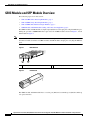
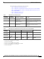
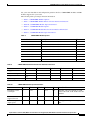
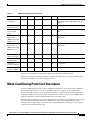
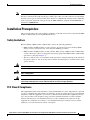
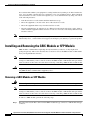
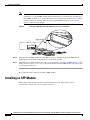
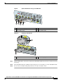
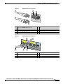
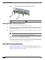
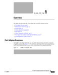
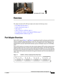
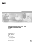
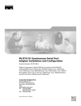
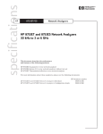
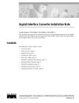
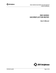
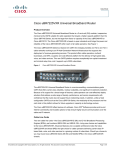
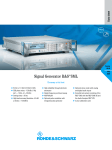
Gigabit Interface Converter (GBIC) Module and
Small Form-Factor Pluggable (SFP) GBIC Module
Installation Information and Specifications
GBIC Product Numbers: WS-G5484, WS-G5486, WS-G5487, CWDM-GBIC-1470=, CWDM-GBIC-1490=,
CWDM-GBIC-1510=, CWDM-GBIC-1530=, CWDM-GBIC-1550=, CWDM-GBIC-1570=, CWDM-GBIC-1590=,
CWDM-GBIC-1610=
SFP Product Numbers: SFP-GE-F=, SFP-GE-S=, SFP-GE-L=, SFP-GE-Z=, GLC-SX-MM=, GLC-LH-SM=, GLC-ZX-SM=,
GLC-T=, CWDM-SFP-1470=, CWDM-SFP-1490=, CWDM-SFP-1510=, CWDM-SFP-1530=, CWDM-SFP-1550=,
CWDM-SFP-1570=, CWDM-SFP-1590=, CWDM-SFP-1610=
Revision History Table
The Document Revision History table below, beginning with OL-5007-06, records technical changes to
this document.
Document Version
Date
Change Summary
OL-5067-08
August, 2008
This version adds SFP module SFP-GE-F information.
OL-5067-07
April, 2007
This version adds Cisco 7201 support.
OL-5067-06
December, 2006
This version adds SFP module SFP-GE-S, SFP-GE-L,
and SFP-GE-Z information.
Introduction
This document provides information about Gigabit Interface Converter (GBIC) modules and small
form-factor (SFP) GBIC modules on the Cisco 7200VXR routers, the Cisco 7201 router, the Cisco 7301
router, the Cisco 7304 router, the Cisco 7401ASR router, the Cisco 7500 series routers, the Cisco 7600
series routers, the Cisco 10008 router, the Cisco 12000 series routers, and the Cisco uBR7246VXR cable
Americas Headquarters:
Cisco Systems, Inc., 170 West Tasman Drive, San Jose, CA 95134-1706 USA
© 2007 Cisco Systems, Inc. All rights reserved.
Contents
router and Cisco uBR10012 cable router. The GBIC modules and SFP modules are input/output devices
that plug into a Gigabit Ethernet (GE) port, linking the port with a 1000BASE-X fiber-optic network.
The devices are used on Cisco platforms that have Gigabit Ethernet interfaces.
Also see the documentation that shipped with the GBIC module or SFP module or the installation guide
for your router, I/O controller, processor engine, or port adapter.
Contents
This document contains the following sections:
•
Related Documentation, page 2
•
GBIC Module and SFP Module Overview, page 4
•
Cisco 1000BASE-T SFP Modules, page 9
•
CWDM GBIC Module and SFP Module Description and Information, page 9
•
Mode-Conditioning Patch Cord Description, page 13
•
Installation Prerequisites, page 15
•
Installing and Removing the GBIC Module or SFP Module, page 16
•
Installing a GBIC Module, page 17
•
Installing an SFP Module, page 18
•
Installing the GBIC Module or SFP Module Interface Cables, page 20
•
Fiber-Optic Cleaning Information, page 22
•
Obtaining Documentation, Obtaining Support, and Security Guidelines, page 23
Related Documentation
The Cisco IOS software running on your router contains extensive features and functionality, which are
documented online and in the following resources:
•
Cisco IOS software configuration documentation contains Cisco IOS software configuration
information and support. See the modular configuration and modular command reference
publications in the set that corresponds to the software release installed on your Cisco hardware.
Access these documents at:
http://www.cisco.com/en/US/products/sw/iosswrel/tsd_products_support_category_home.html
For hardware installation and maintenance information, refer to the following documents:
•
Cisco 7200 series routers:
Cisco 7200 Series Routers Documentation Roadmap
•
Cisco 7201 router:
Cisco 7201 Router Documentation Roadmap
•
Cisco 7301 router:
Cisco 7301 Internet Router Documentation Roadmap
Cisco 7304 routerCisco 7304 Internet Router Documentation Roadmap
•
2
Cisco 7401ASR router:
Gigabit Interface Converter (GBIC) Module and Small Form-Factor Pluggable (SFP) GBIC Module Installation Information and Specifications
OL-5067-08
Related Documentation
Cisco 7401ASR Router Documentation Roadmap
•
Cisco 7500 series routers:
Cisco 7500 Series Routers Documentation Roadmap
•
Cisco 7600 series routers:
– Cisco 7600 Series Internet Router Installation Guide
– Cisco 7609 Internet Router Installation Guide
•
Cisco 10000 ESR routers:
Cisco 10000 Series Routers Line Card Hardware Installation Guide
Cisco 12000 series routersCisco 12000 Series Internet Router Line Card Documentation Roadmap
•
Cisco uBR7246VXR cable router and Cisco uBR10012 cable router:
– Cisco uBR10012 Universal Broadband Router Hardware Installation Guide
– Cisco uBR7246VXR Universal Broadband Router Hardware Installation
•
For international agency compliance, safety, and statutory information for WAN interfaces:
– Site Preparation and Safety Guide
– Regulatory Compliance and Safety Information for the Cisco 7200 Series Routers
– Regulatory Compliance and Safety Information for the Cisco 7301 Internet Router
– Regulatory Compliance and Safety Information for Cisco 7304 Internet Router
– Regulatory Compliance and Safety Information for the Cisco 7401ASR Internet Router
– Regulatory Compliance and Safety Information for Cisco 7500 Series Routers
– Regulatory Compliance and Safety Information for the Cisco 7600 Series Routers
– Regulatory Compliance and Safety Information for Cisco 12000 Series Internet Routers
•
To view Cisco documentation or obtain general information about the documentation, refer to the
“Obtaining Documentation, Obtaining Support, and Security Guidelines” section on page 23.
Gigabit Interface Converter (GBIC) Module and Small Form-Factor Pluggable (SFP) GBIC Module Installation Information and Specifications
OL-5067-08
3
GBIC Module and SFP Module Overview
GBIC Module and SFP Module Overview
The following topics are in this section:
•
SFP and GBIC Short Wavelength Modules, page 7
•
SFP and GBIC Long Wavelength Modules, page 7
•
SFP and GBIC Extended Wavelength Modules, page 7
•
GBIC Module and SFP Module Cabling and Connection Equipment, page 8
The GBIC module and SFP module are input/output (I/O) devices that plug into a Gigabit Ethernet port,
linking the port with a 1000BASE-X fiber-optic network. A GBIC module is shown in Figure 1, and an
SFP module in Figure 2.
Note
Other GBIC modules and SFP modules exist for technologies other than Gigabit Ethernet. However, the
information in this document is for GBIC modules and SFP modules that plug in to only Gigabit Ethernet
ports.
GBIC Module
101308
Figure 1
1
1
2
2
Receiver (RX)
SFP Module
101310
Figure 2
Transmitter (TX)
The GBIC module and SFP module have a receiver port (RX) and a transmitter port (TX) that make up
one optical interface.
4
Gigabit Interface Converter (GBIC) Module and Small Form-Factor Pluggable (SFP) GBIC Module Installation Information and Specifications
OL-5067-08
GBIC Module and SFP Module Overview
The following tables provide information and specifications:
Table 1
•
Table 1, “GBIC Module and SFP Module Options”
•
Table 2, “GBIC Module and SFP Module Transmit Power, Receive Power, and Power Budget”
•
Table 3, “SFP-GE-F, SFP-GE-L, SFP-GE-S, and SFP-GE-Z Module Transmit Power, Receive
Power, and Power Budget”
•
Table 4, “GBIC Module Specifications”
•
Table 5, “SFP Module Specifications”
GBIC Module and SFP Module Options
GBIC Module
Product Number
SFP Module
Product Number
WS-G5484
GBIC Module or SFP Module
Description
GLC-SX-MM
Short wavelength
(1000BASE-SX)
Contains a Class 1 laser of 850 nm for
1000BASE-SX (short wavelength) applications.
WS-G5486
GLC-LH-SM
Long wavelength/long haul
(1000BASE-LX/LH)
Contains a Class 1 laser of 1300 nm for
1000BASE-LX/LH (long wavelength)
applications.
WS-G5487
GLC-ZX-SM
Extended distance
(1000BASE-ZX)
Contains a Class 1 laser of 1550 nm for
1000BASE-ZX (extended wavelength)
applications.
Table 2
GBIC Module and SFP Module Transmit Power, Receive Power, and Power Budget
Transmit Power
GBIC Module
and SFP Module Minimum
1
WS-G5484 and
GLC-SX-MM
–9.5 dBm
WS-G5486 and
GLC-LH-SM
–9.5 dBm3
WS-G5487 and
GLC-ZX-SM
Receive Power
Maximum
Power Budget
Minimum
Maximum
1
–17 dBm
0 dBm
7.5 dBm2
–3 dBm5
–20 dBm
–3 dBm
7.5 dBm6 and 8.0 dBm7
5.2 dBm
–24 dBm
–3 dBm
–24 dBm
–3 dBm
–11.5dBm4
0 dBm
µm, NA = 0.20 fiber and 62.5/125 µm, NA = 0.275 fiber.
µm MMF and 62.5/125 µm MMF.
For fiber types 9/125 µ m SMF.
For fiber types 62.5/125 µm MMF and 50/125 µm MMF.
For fiber types 9/125 µ m SMF, 62.5/125 µm MMF, and 50/125 µ m MMF.
For fiber types 50/125 µm MMF and 62.5/125 µm MMF.
For fiber type 10 µm SMF.
1. For fiber types 50/125
2. For fiber types 50/125
3.
4.
5.
6.
7.
Gigabit Interface Converter (GBIC) Module and Small Form-Factor Pluggable (SFP) GBIC Module Installation Information and Specifications
OL-5067-08
5
GBIC Module and SFP Module Overview
Table 3 provides power budget information for the SFP-GE-F, SFP-GE-L, SFP-GE-S, and SFP-GE-Z
modules.
Table 3
SFP-GE-F, SFP-GE-L, SFP-GE-S, and SFP-GE-Z Module Transmit Power, Receive Power, and Power Budget
SFP Modules
Transmit Power
Receive Power
Power Budget
Minimum
Maximum
Minimum
Maximum
-23.5
-20
-14
-14
-33.5
-33.5
-11.8
-11.8
10 dBm
13.5 dBm
SFP-GE-L
-9.5 dBm1
-11.5dBm2
-3 dBm3
-20 dBm
-3 dBm
7.5 dBm4 and 8.0
dBm5
SFP-GE-S
-9.5 dBm6
-3 dBm 1
-17 dBm
0 dBm
7.5 dBm7
SFP-GE-Z
0 dBm
5 dBm
-23 dBm
0 dBm
-24 dBm
SFP-GE-F=
For 50/125 cabling
For 62.5/125 cabling
1. For fiber types 9/125 mm SMF.
2. For fiber types 62.5/125 mm MMF and 50/125 mm MMF.
3. For fiber types 9/125 mm SMF, 62.5/125 mm MMF, and 50/125 mm MMF.
4. For fiber types 50/125 mm MMF and 62.5/125 mm MMF.
5. For fiber type 10 mm SMF.
6. For fiber types 50/125 mm, NA = 0.20 fiber and 62.5/125 mm, NA = 0.275 fiber.
7. For fiber types 50/125 mm MMF and 62.5/125 mm MMF.
Table 4 lists the GBIC module physical specifications and Table 5 lists the SFP module physical
specifications.
Table 4
Specification
Description
Dimensions (H x W x D)
0.39 in. x 1.18 in. x 2.56 in.
(1 cm x 3 cm x 6.5 cm)
Connectors
Multimode fiber-optic: SC-type connector
Single-mode fiber-optic: SC-type connector
Wavelength
WS-G5484: 850 nm
WS-G5486: 1300 nm
WS-G5487: 1550 nm
Cabling distance
(maximum)
WS-G5484: 1804 feet (550 m)
WS-G5486: 6.2 miles (10 km)
WS-G5487: 43.5 to 62.1 miles (70 to 100 km)
Table 5
6
GBIC Module Specifications
SFP Module Specifications
Specification
Description
Dimensions (H x W x D)
0.33 in x 0.53 in x 2.22 in (8.5 mm x 13.4 mm x
56.5 mm)
Connectors
Multimode fiber-optic: LC-type connector
Single-mode fiber-optic: LC-type connector
Gigabit Interface Converter (GBIC) Module and Small Form-Factor Pluggable (SFP) GBIC Module Installation Information and Specifications
OL-5067-08
GBIC Module and SFP Module Overview
Table 5
SFP Module Specifications (continued)
Specification
Description
Wavelength
GLC-SX-MM: 850 nm
GLC-LH-SM: 1300 nm
GLC-ZX-SM: 1550 nm
GLC-GE-FX: 1300 nm
Cabling distance
(maximum)
GLC-SX-MM: 1804 feet (550 m)
GLC-LH-SM: 6.2 miles (10 km)
GLC-ZX-SM: 43.5 to 62.1 miles (70 to 100 km)
GLC-GE-FX: 1.2428 miles (2 km)
SFP and GBIC Short Wavelength Modules
The 1000BASE-SX (short wavelength) GBIC module operates on standard multimode fiber-optic link
spans of up to 1804 feet (550 m). (See Table 6.)
The 100BASE-FX SFP module is a hot-swappable device that plugs into a Gigabit Ethernet SFP port. It
provides full-duplex 100-Mbps connectivity over multimode fiber (MMF) infrastructures. The
100BASE-FX SFP operates on ordinary MMF optical link spans of up to 1.2428 miles (2 km) in length.
SFP and GBIC Long Wavelength Modules
The 1000BASE-LX/LH (long wavelength/long haul) GBIC module interfaces fully comply with the
IEEE 802.3z 1000BASE-LX standard. However, their higher optical quality allows them to reach
6.2 miles (10 km) over single-mode fiber (SMF) versus the 3.1 miles (5 km) specified in the standard.
SFP and GBIC Extended Wavelength Modules
The 1000BASE-ZX (extended wavelength) GBIC module operates on ordinary single-mode fiber-optic
link spans of up to 43.5 miles (70 km). Link spans of up to 62.1 miles (100 km) are possible using
premium single-mode fiber or dispersion-shifted single-mode fiber (premium single-mode fiber has a
lower attenuation per unit length than ordinary single-mode fiber; dispersion-shifted single-mode fiber
has both lower attenuation and less dispersion).
The 1000BASE-ZX GBIC module must be coupled to single-mode fiber-optic cable, which is the type
of cable typically used in long-haul telecommunications applications. The 1000BASE-ZX GBIC module
will not operate correctly when coupled to multimode fiber, and it is not intended to be used in
environments where multimode fiber is frequently used (for example, building backbones, or horizontal
cabling).
The 1000BASE-ZX GBIC module is intended to be used as a Physical Medium Dependent (PMD)
component for Gigabit Ethernet interfaces found on various switch and router products. It operates at a
signaling rate of 1250 Mbaud, transmitting and receiving 8B/10B encoded data.
When shorter lengths of single-mode fiber are used, it may be necessary to insert an in-line optical
attenuator in the link to avoid overloading the receiver.
•
Insert a 10-dB in-line optical attenuator between the fiber-optic cable plant and the receiving port
on the 1000BASE-ZX GBIC module at each end of the link whenever the fiber-optic cable span is
less than 15.5 miles (25 km).
Gigabit Interface Converter (GBIC) Module and Small Form-Factor Pluggable (SFP) GBIC Module Installation Information and Specifications
OL-5067-08
7
GBIC Module and SFP Module Overview
•
Insert a 5-dB in-line optical attenuator between the fiber-optic cable plant and the receiving port on
the 1000BASE-ZX GBIC module at each end of the link whenever the fiber-optic cable span is equal
to or greater than 15.5 miles (25 km) but less than 31 miles (50 km).
GBIC Module and SFP Module Cabling and Connection Equipment
The GBIC module port is a 1000-Mbps optical interface in the form of an SC-type duplex port (see
Figure 1) that supports IEEE 802.3z interfaces compliant with the 1000BASE-X standard.
Table 6 provides cabling specifications for the GBIC modules and SFP modules that you install in
Gigabit Ethernet devices. Note that all GBIC module ports have SC-type connectors and all SFP ports
have LC-type connectors.
The minimum cable distance for the WS-G5484 or GLC-SX-MM and WS-G5486 or GLC-LH-SM
(multimode fiber [MMF] and single-mode fiber [SMF]) is 6.5 feet (2 m), and the minimum link distance
for the WS-G5487 or GLC-ZX-SM is 6.2 miles (10 km) with an 8-dB attenuator installed at each end of
the link. Without attenuators, the minimum link distance for the WS-G5487 or GLC-ZX-SM is 24.9
miles (40 km).
Table 6
GBIC and SFP Module Port Cabling Specifications
GBIC Module
SFP Modules
WS-G5484 or
GLC-SX-MM
SFP-GE-S or
GLC-SX-MM
WS-G5486 or
GLC-LH-SM
WS-G54873 or
GLC-ZX-SM
GLC-GE-100FX
SFP-GE-L or
GLC-LH-SM
SFP-GE-Z or
GLC-ZX-SM
SFP-GE-F
Wavelength
(nm)
850
1300
1550
1270 (min),
1300 (avg),
1380 (max)
Fiber Type
Core Size
(micron)
Modal
Bandwidth
(MHz-km)
Maximum
Cable Distance
MMF1
62.5
160
722 ft (220 m)
62.5
200
902 ft (275 m)
50.0
400
1640 ft (500 m)
50.0
500
1804 ft (550 m)
62.5
500
1804 ft (550 m)
50.0
400
1804 ft (550 m)
50.0
500
1804 ft (550 m)
9/10
—
6.2 miles (10 km)
SMF
9/10
—
43.5 miles
(70 km)
SMF4
8
—
62.1 miles
(100 km)
MMF
62.5
500
1.4 miles (6562
ft)
2
MMF and
SMF
62.5
50.0
50.0
1. Multimode fiber (MMF) only.
8
Gigabit Interface Converter (GBIC) Module and Small Form-Factor Pluggable (SFP) GBIC Module Installation Information and Specifications
OL-5067-08
Cisco 1000BASE-T SFP Modules
2. A mode-conditioning patch cord is required.
When using the WS-G5486 or GLC-LH-SM with 62.5-micron diameter MMF, you must install a mode-conditioning patch cord between the GBIC module
or SFP module and the MMF cable on both the transmit and the receive ends of the link when link distances are greater than 984 ft (300 m).
We do not recommend using the WS-G5486 or GLC-LH-SM and MMF with no patch cord for very short link distance (tens of meters). The result could
be an elevated bit error rate (BER).
3. You can have a maximum of 12 1000BASE-ZX GBIC modules or SFP modules per system to comply with EN55022 Class B and 24 1000BASE-ZX
GBIC modules or SFP modules per system to comply with FCC Class A regulations.
4. Dispersion-shifted single-mode fiber-optic cable.
Note
The 1000BASE-ZX GBIC module and SFP modules provide an optical power budget of 21.5 dB. You
should measure your cable plant with an optical loss test set to verify that the optical loss of the cable
plant (including connectors and splices) is less than or equal to 21.5 dB. The optical loss measurement
must be performed with a 1550-nm light source.
Cisco 1000BASE-T SFP Modules
The 1000BASE-T (GLC-T) SFP module is compliant with IEEE 802.3:2000 and plugs into a standard
Gigabit Ethernet SFP module port. It operates on standard Category 5 wiring and has an RJ-45
connector.
See your router installation and configuration guide to determine which routers support the GLC-T SFP
module.
Table 7
GLC-T SFP Module Specifications
Specification
Description
Dimensions (H x W x D)
.055 in. x .054 in. x 2.8 in (14.0 mm. x 13.7 mm.
x 71.1 mm)
Cabling Distance (maximum)
328 feet (100 m)
Power consumption
1.1W
Product number
GLC-T=
CWDM GBIC Module and SFP Module Description and
Information
Coarse Wavelength-Division Multiplexing (CWDM) GBIC modules and Coarse Wavelength-Division
Multiplexing (CWDM) SFP modules are supported on a variety of Cisco products. For more
information, see the Cisco CWDM GBIC Compatibility Matrix and the Cisco Coarse
Wavelength-Division Multiplexing SFP Compatibility Matrix.
Gigabit Interface Converter (GBIC) Module and Small Form-Factor Pluggable (SFP) GBIC Module Installation Information and Specifications
OL-5067-08
9
CWDM GBIC Module and SFP Module Description and Information
CWDM GBIC Module
7
1
100 SING
CWD 0BASE LE-M
M-G -CW OD
B
I
C-15 DM GB E
50= IC
Figure 3
2
6
4
84472
5
3
1
Color band on label
5
Optical bore dust plug
2
Alignment groove
6
Receive optical bore
3
Spring clip
7
Color dot
4
Transmit optical bore
Figure 4
CWDM SFP Module
C
C WD
l
L as M
N
S # s -S
/N 50 1 F
: 7 21 PO / C 14
H 01 F 7
1 R 0
2 1 3 0 2
3 4 G
4 0
5 .
6 0 1
3 0
-1
3
1
5
2
94071
3
4
1
Color arrow on label
4
Color coded bale clasp
2
Receive optical bore
5
Optical bore dust plug
3
Transmit optical bore
The Cisco CWDM GBIC module and SFP modules enables the transport of up to eight channels (Gigabit
Ethernet over single-mode fiber strands. (They also support the transport of up to eight channels [Fiber
Channel] over single-mode strands, although Fiber Channel is not discussed in this document.) Cisco
CWDM GBIC modules have SC-type connectors, and Cisco CWDM SFP modules have LC-type
connectors. They are compatible with 1000BASE-X standard as specified in IEEE 802.3z. The Cisco
CWDM GBUC modules and SFP modules are passive and require no power nor configuration. The Cisco
CWDM modules support online insertion and removal (OIR).
10
Gigabit Interface Converter (GBIC) Module and Small Form-Factor Pluggable (SFP) GBIC Module Installation Information and Specifications
OL-5067-08
CWDM GBIC Module and SFP Module Description and Information
See your router installation and configuration guide for the Cisco CWDM GBIC modules and SFP
modules supported on your router.
The following tables provide specification information:
•
Table 8, “CWDM GBIC Module Options”
•
Table 9, “CWDM GBIC Module Electrical Power Interface Information”
•
Table 10, “CWDM GBIC Module Optical Parameters”
•
Table 11, “CWDM SFP Module Options”
•
Table 12, “CWDM SFP Module Electrical Power Interface Information”
•
Table 13, “CWDM SFP Module Optical Parameters”
Table 8
Table 9
CWDM GBIC Module Options
Product Number
Description
Color
CWDM-GBIC-1470=
Cisco 1000BASE-CWDM GBIC 1470 nm
Gray
CWDM-GBIC-1490=
Cisco 1000BASE-CWDM GBIC 1490 nm
Violet
CWDM-GBIC-1510=
Cisco 1000BASE-CWDM GBIC 1510 nm
Blue
CWDM-GBIC-1530=
Cisco 1000BASE-CWDM GBIC 1530 nm
Green
CWDM-GBIC-1550=
Cisco 1000BASE-CWDM GBIC 1550 nm
Yellow
CWDM-GBIC-1570=
Cisco 1000BASE-CWDM GBIC 1570 nm
Orange
CWDM-GBIC-1590=
Cisco 1000BASE-CWDM GBIC 1590 nm
Red
CWDM-GBIC-1610=
Cisco 1000BASE-CWDM GBIC 1610 nm
Brown
CWDM GBIC Module Electrical Power Interface Information
Parameter
Symbol
Minimum
Typical
Maximum
Units
Supply Current
Is
–
280
350.0
mA
Maximum voltage
Vmax
–
–
6.0
V
Surge current
ISurge
–
–
400.0
mA
Input voltage
Vcc
4.75
5
5.25
V
Table 10
CWDM GBIC Module Optical Parameters
Parameter
Symbol
Minimum
Typical
Maximum
Units
Notes/Conditions
Transmitter center
wavelength
λC
(x–4)
–
(x+7)
nm
Available center wavelengths are 1470,
1490, 1510, 1530, 1550, 1570, 1590, and
1610 nm
Side-mode
suppression ratio
SMSR
30
–
–
db
–
Transmitter optical
output power
Pout
+1.0
+3.0
+5.0
dBm
Average power coupled into single-mode
fiber
Gigabit Interface Converter (GBIC) Module and Small Form-Factor Pluggable (SFP) GBIC Module Installation Information and Specifications
OL-5067-08
11
CWDM GBIC Module and SFP Module Description and Information
Table 10
CWDM GBIC Module Optical Parameters (continued)
Parameter
Symbol
Minimum
Typical
Maximum
Units
Notes/Conditions
Receiver optical
input power
(BER <10-12 with
PRBS 2-7-1)
Pin
–29.0
–33.0
–7.0
dBm
@ 1.25 Gbps, 140°F (60°C) case
temperature
Optical input
wavelength
λin
1450
–
1620.0
nm
–
Transmitter
extinction ratio
OMI
9
–
–
dB
–
–
–
3.0
dB
@ 1.25 Gbps
Dispersion penalty at –
100 km
Parameters are specified over temperature and at end of life unless otherwise noted.
When shorter distances of single-mode fiber are used, it may be necessary to insert an in-line optical
attenuator in the link to avoid overloading the receiver.
Table 11
Table 12
CWDM SFP Module Options
Product Number
Description
Color
CWDM-SFP-1470=
Cisco 1000BASE-CWDM SFP 1470 nm
Gray
CWDM-SFP-1490=
Cisco 1000BASE-CWDM SFP 1490 nm
Violet
CWDM-SFP-1510=
Cisco 1000BASE-CWDM SFP 1510 nm
Blue
CWDM-SFP-1530=
Cisco 1000BASE-CWDM SFP 1530 nm
Green
CWDM-SFP-1550=
Cisco 1000BASE-CWDM SFP 1550 nm
Yellow
CWDM-SFP-1570=
Cisco 1000BASE-CWDM SFP 1570 nm
Orange
CWDM-SFP-1590=
Cisco 1000BASE-CWDM SFP 1590 nm
Red
CWDM-SFP-1610=
Cisco 1000BASE-CWDM SFP 1610 nm
Brown
CWDM SFP Module Electrical Power Interface Information
Parameter
Symbol
Minimum
Typical
Maximum
Units
Supply current
Is
–
220
300
mA
Surge current
ISurge
–
–
+30
mA
Input voltage
Vmax
3.1
3.3
3.6
V
12
Gigabit Interface Converter (GBIC) Module and Small Form-Factor Pluggable (SFP) GBIC Module Installation Information and Specifications
OL-5067-08
Mode-Conditioning Patch Cord Description
Table 13
CWDM SFP Module Optical Parameters
Parameter
Symbol
Minimum
Typical
Maximum
Units
Notes/Conditions
Transmitter center λC
wavelength
(x–4)
–
(x+7)
nm
Available center wavelengths are 1470,
1490, 1510, 1530, 1550, 1570, 1590, and
1610 nm
Side-mode
suppression ratio
SMSR
30
–
–
dB
–
Transmitter
optical output
power
Pout
0
–
5.0
dBm
Average power coupled into single-mode
fiber
Pin
Receiver optical
input power
(BER <10-12 with
PRBS 2-7-1)
–28
–
–7.0
dBm
@ 2.12 Gbps, 140° F (60° C) case
temperature
Pin
Receiver optical
input power
(BER <10-12 with
PRBS 2-7-1)
–29
–
–7.0
dBm
@ 1.25 Gbps, 140° F (60° C) case
temperature
Receiver optical
input wavelength
λin
1450
–
1620
nm
–
Transmitter
extinction ratio
OMI
9
–
–
dB
–
Dispersion
–
penalty at 100 km
–
–
3
dB
@ 2.12 Gbps
Dispersion
–
penalty at 100 km
–
–
2
dB
@ 1.25 Gbps
Parameters are specified over-temperature and at end-of-life unless otherwise noted.
When shorter distances of single-mode fiber are used, it may be necessary to insert an in-line optical
attenuator in the link to avoid overloading the receiver.
Mode-Conditioning Patch Cord Description
A mode-conditioning patch cord can be used with the WS-G5486 to allow reliable laser transmission
between the single-mode laser source on the GBIC module and a multimode optical fiber cable.
When an unconditioned laser source designed for operation on single-mode optical fiber is directly
coupled to a multimode optical fiber cable, an effect known as differential mode delay (DMD) might
result in a degradation of the modal bandwidth of the optical fiber cable.
This degradation results in a decrease in the link span (the distance between a transmitter and a receiver)
that can be supported reliably. The effect of DMD can be overcome by conditioning the launch
characteristics of a laser source. A practical means of performing this conditioning is to use a device
called a mode-conditioning patch cord.
Gigabit Interface Converter (GBIC) Module and Small Form-Factor Pluggable (SFP) GBIC Module Installation Information and Specifications
OL-5067-08
13
Mode-Conditioning Patch Cord Description
A mode-conditioning patch cord is an optical fiber cable assembly that consists of a pair of optical fibers
terminated with connector hardware. Specifically, the mode-conditioning patch cord is composed of a
single-mode optical fiber permanently coupled off-center (see Offset in Figure 5 and Figure 6) to a
graded-index multimode optical fiber. Figure 5 and Figure 6 show a diagram of the mode-conditioning
patch cord assembly.
Figure 5
Mode Conditioning Patch Cord Assembly with GBIC Module-Type Connector
6
1
3
//
Offset
//
7
8
6
9
57011
2
RX
1
//
TX
4
5
1
1
Beige color identifier
6
Multimode fiber
2
To GE interface
7
Single-mode fiber
3
RX
8
Offset
4
TX
9
To cable plant
5
Blue color identifier
Figure 6
Mode Conditioning Patch Cord Assembly with SFP Module-Type Connector
4
1
//
2
//
Offset
8
TX
3
5
6
7
4
1
Gray color identifier
5
Single-mode bar
2
To GE interface
6
Offset
3
Blue color identifier
7
Beige color identifier
4
Multimode bar
8
To cable plant
84159
RX
7
//
The mode-conditioning patch cord assembly is composed of duplex optical fibers, including a
single-mode-to-multimode offset launch fiber connected to the transmitter, and a second conventional
graded-index multimode optical fiber connected to the receiver. The use of a plug-to-plug patch cord
maximizes the power budget of multimode 1000BASE-LX and 1000BASE-LH links.
14
Gigabit Interface Converter (GBIC) Module and Small Form-Factor Pluggable (SFP) GBIC Module Installation Information and Specifications
OL-5067-08
Installation Prerequisites
Note
The mode-conditioning patch cord is required to comply with IEEE standards. The IEEE found that link
distances could not be met with certain types of fiber-optic cable cores. The solution is to launch light
from the laser at a precise offset from the center, which is accomplished by using the mode-conditioning
patch cord. At the output end of the patch cord, the GBIC-LX/LH is compliant with the IEEE 802.3z
standard for 1000BASE-LX.
Installation Prerequisites
This section describes safety and compliance guidelines you should observe before you install the GBIC
module or SFP module in your Gigabit Ethernet device.
Safety Guidelines
Before handling a GBIC module or SFP module, observe the following guidelines:
•
GBIC modules and SFP modules are static-sensitive. To prevent electrostatic discharge (ESD)
damage, follow your normal board- and component-handling procedures.
•
GBIC modules and SFP modules are dust-sensitive. When storing a GBIC module or SFP module
or when a fiber-optic cable is not plugged in, always keep plugs in the GBIC module or SFP module
optical bores. (See plug in Figure 7.)
•
The most common source of contaminants in the optical bores is debris picked up on the ferrules of
the optical connectors. Use an alcohol swab or lint-free absorbent wipes to clean the ferrules of the
optical connector.
Warning
Class 1 laser product.
Warning
Class 1 LED product.
Warning
Because invisible laser radiation may be emitted from the aperture of the port when no fiber cable is
connected, avoid exposure to laser radiation and do not stare into open apertures.
FCC Class A Compliance
This equipment has been tested and found to comply with the limits for a Class A digital device, pursuant
to part 15 of the FCC rules. These limits are designed to provide reasonable protection against harmful
interference when the equipment is operated in a commercial environment. This equipment generates,
uses, and can radiate radio-frequency energy and, if not installed and used in accordance with the
instruction manual, may cause harmful interference to radio communications. Operation of this
equipment in a residential area is likely to cause harmful interference, in which case users will be
required to correct the interference at their own expense.
Gigabit Interface Converter (GBIC) Module and Small Form-Factor Pluggable (SFP) GBIC Module Installation Information and Specifications
OL-5067-08
15
Installing and Removing the GBIC Module or SFP Module
You can determine whether your equipment is causing interference by turning it off. If the interference
stops, it was probably caused by the Cisco equipment or one of its peripheral devices. If the equipment
causes interference to radio or television reception, try to correct the interference by using one or more
of the following measures:
Note
•
Turn the television or radio antenna until the interference stops.
•
Move the equipment to one side or the other of the television or radio.
•
Move the equipment farther away from the television or radio.
•
Plug the equipment into an outlet that is on a different circuit from the television or radio. (That is,
make certain the equipment and the television or radio are on circuits controlled by different circuit
breakers or fuses.)
This product has been designed to meet these requirements. Modifications to this product that are not
authorized by Cisco , could void the various approvals and negate your authority to operate the product.
Installing and Removing the GBIC Module or SFP Module
GBIC modules or SFP modules might ship already installed in your device, or they might arrive
packaged separately. This section describes how to install or remove the GBIC module or SFP module
from your Gigabit Ethernet interface.
Note
Caution
You can install and remove GBIC modules or SFP modules with power on to the system; however, we
strongly recommend that you do not install or remove the GBIC module or SFP module with optical fiber
cables attached to it. Disconnect all cables before removing or installing a GBIC module or SFP module.
To prevent system problems, do not use GBIC modules or SFP modules from third-party vendors. Use
only GBIC modules or SFP modules supplied by Cisco.
Removing a GBIC Module or SFP Module
Warning
Note
Ultimate disposal of this product should be handled according to all national laws and regulations.
You can install and remove GBIC modules or SFP modules with power on to the system; however, we
strongly recommend that you do not install or remove the GBIC module or SFP module with optical fiber
cables attached to it. Disconnect all cables before removing or installing a GBIC module or SFP module.
To remove a GBIC module, perform the following steps:
Step 1
16
Disconnect the network fiber cable from the GBIC module SC-type connector or SFP module LC-type
connector.
Gigabit Interface Converter (GBIC) Module and Small Form-Factor Pluggable (SFP) GBIC Module Installation Information and Specifications
OL-5067-08
Installing a GBIC Module
Step 2
Step 3
Release the GBIC module or SFP module.
a.
Release the GBIC module from the slot by simultaneously squeezing the two plastic tabs (one on
each side of the GBIC module).
b.
Release the SFP module. See Figure 11 for the various types of latches that may be on your SFP
module.
Slide the GBIC module or SFP module out of the slot.
This completes the procedure to remove a GBIC module or SFP module from the Gigabit Ethernet
interface.
Installing a GBIC Module
Use the following procedure to install a GBIC module:
Note
A horizontally oriented slot is shown for illustration purposes. Some chassis may have vertically
oriented slots.
Step 1
Attach an ESD-preventive wrist strap between you and an unpainted chassis surface.
Step 2
Locate the alignment groove on the GBIC module (see the enlargement in Figure 7 and Figure 8).
Step 3
Align the groove on the GBIC module with the interface opening (see Figure 7 and Figure 8).
GBIC modules are keyed to prevent incorrect insertion.
Note
Figure 7
Inserting a GBIC Module with Alignment Groove on Top—Cisco 7301 Gigabit Ethernet
Interface Shown
3
ETHER
NET 0
/1
4
GIGAB
IT ETH
ER
LINK
5
RX
GBIC
NET 0
/2
TX
RJ45
EN
RX
GBIC
66774
2
1
1
GBIC module
4
GBIC module port 0/2
2
Alignment groove
5
Plug
3
GBIC module port 0/1
Gigabit Interface Converter (GBIC) Module and Small Form-Factor Pluggable (SFP) GBIC Module Installation Information and Specifications
OL-5067-08
17
Installing an SFP Module
Note
Some horizontally oriented devices accept the GBIC module with the alignment groove on top.
Other devices accept the GBIC module with the alignment groove on the bottom. (See Figure 8.)
If the GBIC module does not go into the interface slot, ensure that the alignment groove and the
interface opening are lined up and, if necessary, flip the GBIC module over (rotate it 180
degrees) and try inserting it again.
Figure 8
Inserting a GBIC Module with Alignment Groove on the Bottom
38581
Alignment groove
Step 4
Carefully slide the GBIC module into the GBIC slot and seat it. When installed, the GBIC module
input/output panel should be flush with the face of the interface panel.
Step 5
Attach the network interface fiber-optic cable, as described in the “Installing the GBIC Module or SFP
Module Interface Cables” section on page 20, remove the plug from the GBIC module optical bores, and
save the plug for future use.
This completes the procedure for installing a GBIC module.
Installing an SFP Module
SFP modules ordered with the system come installed in the system. Optical fiber cables are
commercially available; they are not available from Cisco.
18
Gigabit Interface Converter (GBIC) Module and Small Form-Factor Pluggable (SFP) GBIC Module Installation Information and Specifications
OL-5067-08
Installing an SFP Module
Figure 9
Optical SFP Module and Copper SFP Modules
Cisco 7
201
RJ45 EN
LINK/ACT
V
SFP
GE 0/0
TX
RJ45 EN
CONSOLE
LINK/ACT
V
TX SFP
RX
LINK/ACT
V
SFP
TX
LINK/ACT
V
SFP RX
MNGMNT
USE ONLY
RX
GE 0/1
GE 0/2
AUX
1
2
3
FE 0/0
4
FE
LINK
0
230304
GE 0/3
1
Optical SFP module plug
3
Copper SFP module RJ-45 connector
2
Optical SFP module
4
Copper SFP module
Figure 10
Installing an SFP Module
TX GBIC
RX
1
ETHERNET
0/0
LINK
TX GBIC
RX
TX
LINK
TX GBIC
RX
GIGABIT ET
HERNET 0/2
RJ45 EN
LINK
TX GBIC
RX
AUX
CONSOLE
RX
COMPAC
FLASH
80269
SERIES
2
1
GIGABIT ET
HERNET 0/1
RJ45 EN
SFP port
2
Latch beneath plug
Step 1
Turn the SFP module so the latch is on the bottom. The SFP module is keyed so that it cannot be inserted
incorrectly.
Step 2
Insert the SFP module into an SFP port. Repeat Step 2 if you are inserting a second or third SFP module.
Step 3
Do not remove the SFP module plugs until you are ready to install the cables.
Gigabit Interface Converter (GBIC) Module and Small Form-Factor Pluggable (SFP) GBIC Module Installation Information and Specifications
OL-5067-08
19
Installing the GBIC Module or SFP Module Interface Cables
Figure 11
SFP Module Showing a Variety of Latches
2
3
80755
1
Note
1
Sliding latch
2
Swing and slide latch
3
Swing latch
Different manufacturers have different types of latching mechanisms for Gigabit Ethernet SFP modules.
There is no correlation of the type of latch to the model (such as SX or LH) or technology type (such as
Gigabit Ethernet) of SFP modules. See the label for the SFP technology type and model. The SFP
modules use LC-type connectors.
Installing the GBIC Module or SFP Module Interface Cables
This section describes how to attach the interface cables to the GBIC module or SFP module.
Note
Optical fiber cables are commercially available; they are not available from Cisco Systems.
Attaching Multimode and Single-Mode Optical Fiber Cables
Attach the appropriate optical fiber cable directly to the SC-type receptacle on the GBIC module or the
LC-type connector on the SFP module. You can use either simplex or duplex connectors for most
devices. (See Figure 12.)
Caution
20
•
For simplex connectors, two cables are required, one cable for transmit (TX) and a second cable for
receive (RX).
•
For duplex connectors, only one cable that has both TX and RX connectors is required.
If you plan to use a GBIC-LX/LH or GLC-LH-SM at distances greater than 984.25 feet (300 meters)
over 50/125-micron or 62.5/125-micron multimode fiber, to prevent data transmission problems you
must use the mode-conditioning patch cord. (See the “Attaching the Mode-Conditioning Patch Cord”
section on page 22.)
Gigabit Interface Converter (GBIC) Module and Small Form-Factor Pluggable (SFP) GBIC Module Installation Information and Specifications
OL-5067-08
Installing the GBIC Module or SFP Module Interface Cables
Figure 12
GBIC Module Port Connections
5
1
ETHER
3
6
NET 0
/1
2
GBIC
TX
66775
RX
4
1
To external 1000BASE-X network
5
RX
2
1 duplex connector (RX and TX)
6
TX
3
To external 1000BASE-X network
7
GBIC module port
4
2 simplex connectors
8
RJ-45 port
Figure 13
SFP Module Port Connections
4
6
5
ABIT ETHE
RNET 0/0
LINK
TX GBIC
RX
GIGABIT ET
HERNET 0/1
RJ45 EN
LINK
TX GBIC
RX
GIGABIT ET
HERNET 0/2
RJ45 EN
LINK
TX GBIC
RX
AUX
CONSOLE
CISCO 74
CISCO 7400SERIES
11
2
80749
1
CO
FL
3
1
To external 1000BASE-X network
4
SFP (GE) port 0/1
2
1 duplex connector (RX and TX)
5
RX
3
SFP module
6
TX
Gigabit Interface Converter (GBIC) Module and Small Form-Factor Pluggable (SFP) GBIC Module Installation Information and Specifications
OL-5067-08
21
Fiber-Optic Cleaning Information
Figure 14
RJ-45 Port and Copper SFP RJ-45 Gigabit Ethernet Port Cabling
Cisco 72
01
RJ45 EN
LINK/ACT
V
SFP
CONSOLE
RJ45 EN
TX
LINK/ACT
V
SFP
RX
LINK/ACT
V
SFP
GE 0/0
LINK/ACT
V
TX SFP
RX
MNGMNT
USE ONLY
GE 0/1
GE 0/2
AUX
FE 0/0
FE
LINK
0
230316
GE 0/3
1
2
1
RJ-45 connector
2
Copper SFP module RJ-45 connector
Attaching the Mode-Conditioning Patch Cord
Perform the following steps to attach the mode-conditioning patch cord:
Step 1
Attach the patch cord to the SC-type receptacle on the GBIC module (Figure 5) or the LC-type connector
on the SFP module (Figure 6).
Step 2
Attach the network ends of your patch cord to the appropriate 1000BASE-X equipment in your building
cable plant.
Note
Ensure that you connect the TX and RX ports on one end of the patch cord to the RX and TX
ports (respectively) on the other end. Connect TX to RX and RX to TX.
If you are attaching cables from CWDM GBIC modules or SFP modules to the Cisco optical add-drop
(OADM) modules, see the documentation for the OADM modules.
This completes the procedure for attaching a mode-conditioning patch cord.
Fiber-Optic Cleaning Information
For information about cleaning fiber-optic cable connectors and receptacles, see the Inspection and
Cleaning Procedures for Fiber-Optic Connections document. It provides detailed illustrations and photos of
procedures and equipment required to properly clean fiber-optic connections. Also see the Compressed Air
Cleaning Issues for Fiber-Optic Connections document.
22
Gigabit Interface Converter (GBIC) Module and Small Form-Factor Pluggable (SFP) GBIC Module Installation Information and Specifications
OL-5067-08
Obtaining Documentation, Obtaining Support, and Security Guidelines
Obtaining Documentation, Obtaining Support, and Security
Guidelines
For information on obtaining documentation, obtaining support, providing documentation feedback,
security guidelines, and also recommended aliases and general Cisco documents, see the monthly What’s
New in Cisco Product Documentation, which also lists all new and revised technical documentation at:
http://www.cisco.com/en/US/docs/general/whatsnew/whatsnew.html.
CCVP, the Cisco logo, and Welcome to the Human Network are trademarks of Cisco Systems, Inc.; Changing the Way We Work, Live, Play, and Learn is
a service mark of Cisco Systems, Inc.; and Access Registrar, Aironet, Catalyst, CCDA, CCDP, CCIE, CCIP, CCNA, CCNP, CCSP, Cisco, the Cisco
Certified Internetwork Expert logo, Cisco IOS, Cisco Press, Cisco Systems, Cisco Systems Capital, the Cisco Systems logo, Cisco Unity,
Enterprise/Solver, EtherChannel, EtherFast, EtherSwitch, Fast Step, Follow Me Browsing, FormShare, GigaDrive, HomeLink, Internet Quotient, IOS,
iPhone, IP/TV, iQ Expertise, the iQ logo, iQ Net Readiness Scorecard, iQuick Study, LightStream, Linksys, MeetingPlace, MGX, Networkers,
Networking Academy, Network Registrar, PIX, ProConnect, ScriptShare, SMARTnet, StackWise, The Fastest Way to Increase Your Internet Quotient,
and TransPath are registered trademarks of Cisco Systems, Inc. and/or its affiliates in the United States and certain other countries.
All other trademarks mentioned in this document or Website are the property of their respective owners. The use of the word partner does not imply a
partnership relationship between Cisco and any other company. (0711R)
Copyright © 2008 Cisco Systems, Inc. All rights reserved.
Printed in the USA on recycled paper containing 10% postconsumer waste.
Gigabit Interface Converter (GBIC) Module and Small Form-Factor Pluggable (SFP) GBIC Module Installation Information and Specifications
OL-5067-08
23
Obtaining Documentation, Obtaining Support, and Security Guidelines
24
Gigabit Interface Converter (GBIC) Module and Small Form-Factor Pluggable (SFP) GBIC Module Installation Information and Specifications
OL-5067-08