1
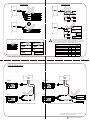
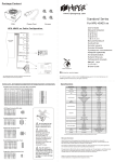
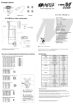
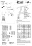
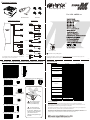
Package Content
TYPE
580W
www.hipergroup.com
For HPU-4M580-xx
PSU
Power Cord
Screws
exTender™
Cables & Connectors
A
250mm (9.8")
A
150mm (5.9")
150mm (5.9")
X
B
350mm (13.8")
150mm (5.9")
B
150mm (5.9")
C
450mm (17.7")
150mm (5.9")
Y
150mm (5.9")
A or B or C
150mm (5.9")
450mm (17.7")
450mm (17.7")
C
150mm (5.9")
150mm (5.9")
150mm (5.9")
X or Y
RoHS compliance
150mm (5.9")
450mm (17.7")
150mm (5.9")
Printed on recycled paper
B or X
The drawings shown are for illustration only and may
differ slightly from the actual product
150mm (5.9")
For technical support, please contact [email protected] or visit www.hipergroup.com
C or Y
©2006 High Performance Group. All rights reserved.
v1.01
Color, pin, and signal assignment of output power connectors:
Spe cifica tion
ATX Main Power Connector, 24 pin (24 to 20pin compatible)
Pin
1
Color
Orange
Signal
+3.3V
Pin
13
2
3
Color
Signal
Orange
+3.3V
Orange
+3.3V
14
Blue
-12V
Black
COM
15
Black
COM
4
Red
+5V
16
Green
PS-ON
5
Black
COM
17
Black
COM
6
Red
+5V
18
Black
COM
7
Black
COM
19
Black
COM
8
Gray
PG
20
N.C.
9
Purple
+5Vsb
21
Red
+5V
10
Yellow
+12V1
22
Red
+5V
11
Yellow
+12V1
23
Red
+5V
12
Orange
+3.3V
24
Black
COM
W attage
1
2
3
4
5
6
7
8
9
10
11
12
+12V Power Connector (P4), 4 pin
Pin
18 AWG Wire
Signal
1
Black
COM
2
Black
COM
3
Yellow
+12v2dc
4
Yellow
+12v2dc
Specifications
13
14
15
16
17
18
19
20
21
22
23
24
Switch Type
Fan
Input Parameter
ATX
Efficiency
Peripheral Power Connector (Molex), 4 pin
4 2
3 1
Pin
18 AWG Wire
Signal
1
Yellow
+12V1dc
2
Black
COM
3
Black
COM
4
Red
+5Vdc
Output Parameter
1
4
Regulation
+12V Power Connector (P8), 8 pin
Pin
18 AWG Wire
Signal
1
Black
COM
2
Black
COM
3
Black
COM
4
Black
COM
5
Yellow
+12v2dc
6
Yellow
+12v2dc
7
Yellow
+12v2dc
8
Yellow
+12v2dc
Output Load Regulation
8
7
6
5
4
3
2
1
Output Voltage Protection
Power Good Signal
Chassis
PFC
PCI-E Power Connector, 6 pin
Pin
18 AWG Wire
Signal
1
Yellow
+12v1dc
2
Yellow
+12v1dc
3
Yellow
+12v1dc
4
Black
COM
5
Black
COM
6
Black
COM
4
5
6
1
2
3
Pin
20 AWG Wire
1-3
Signal
1
2
3
4
5
6
7
8
9
10
11
12
13
14
15
NC
4-6
Black
COM
7-9
Red
+5V
10-12
Black
COM
13-15
Yellow
+12V1
Floppy Drive Power Connector, 4 pin
Pin
22 AWG Wire
Signal
1
Yellow
+12V1dc
2
Black
COM
3
Black
COM
4
Red
+5Vdc
1
4
Unit Size
Dimension
W eight
Net W eight
HPU-4M580-x x
580 W atts
630 W atts
Rocker
ATX Logic
700 ~ 1800 R.P.M.
Sleeve Bearing
195 - 240V
6A
100 - 120V
10A
50 - 60 Hz
2.2
76%
2A - 36A
1A - 20A
1A - 18A
0A - 0.8A
0A - 2.5A
0.5A - 30A
+/- 5%
+/- 5%
+/- 5%
+/- 10%
+/- 5%
+/- 5%
< 360W
< 240W
< 560W
< 4.5V
< 6.8V
< 15.6V
< 20 ms
100 - 500 ms
< 1 ms
16 ms min
1.0 mm
Active (N/A for US model)
150 x 140 x 86 mm
5.9" x 5.5" x 3.4"
2 kg
* Features and specifications are subject to change without prior notice.
Do not open the top
cover to avoid electrical
shock or possible injury.
Serial ATA Power Connector, 15 pin
De scription
Rated W attage
Peak Load
Manual
Auto Standby
120 mm - R.P.M.
120 mm - Type
Voltage Range
Current
Voltage Range (for US model)
Current (for US model)
Frequency Range
Form Factor
Average
+5V
+12V 1
+12V 2
-12V
+5VSB
+3.3V
+5V
+12V 1
+12V 2
-12V
+5VSB
+3.3V
+12V 1 & +12V 2
+3.3V & +5V
+3.3V, +5V & +12V
+3.3V
+5V
+12V
Rise Time
Signal On
Signal Off
Power Hold
Thickness
Power Factor Correction
For US model it is
100-120V, for EU model it
is 195-240V. Please do not
use the incorrect model for
your area in terms of
voltage as it might damage
the PSU.
Warranty Information
High Performance Group guarantees that this device is free of defect in material &
workmanship, and provides three-year RTB warranty for the device, commencing form the
date of purchase. Please keep your receipt in a safe place.
This product is designed for computer usage only. Using this device in any other application
will void the warranty. lf please ask for professional assistance.
The warranty is offered to the device caused by normal use. The warranty is void if determined
that the device is damaged because of abuse, alteration, misuse, negligence, incorrect
voltage supply, air /water pollution accidents and natural calamities.
SATA HDD
Peripherals
10A max
10A max
SATA
SATA
SATA
SATA
case fan
10A max
DVD
10A max
SATA
CD Writer
SATA
Functional Panel
Floppy
Each Molex cable (from PSU) has capacity of approximately 10A
(12V+5V) due to wire limitations. When using eXtender TM to connect
devices, for stability, it is recommended that you do not connect over
4 peripherals with a maximum of 3 hard or optical drives.
For each Molex cable (from PSU):
DVD
DVD
CD Writer
CD Writer
SATA
SATA
Typical Current Consumption (Estimates)
Devices
+5V
+12V
Total (A)
0.25
0.25
2.8
High performance fan
SATA
DVD
CD Writer
DVD
Floppy
High performance hard drive
0.8
2
CD-RW
1.2
0.8
2
DVD
1.2
1.1
2.3
Floppy
0.8
PCI-E VGA Card
0.8
7
7
PCI-E VGA card
PCI-E
PCI-E
Type II
SLi
Type II
SLi
DVD
CD Writer
Floppy
SLi is for HPU-4x5xx and higher model
SLi is for HPU-4x5xx and higher model
The drawings shown are for illustration only and may
differ slightly from the actual product
Printed on recycled paper