1
Cisco 7204 Installation and Configuration
Guide
Corporate Headquarters
Cisco Systems, Inc.
170 West Tasman Drive
San Jose, CA 95134-1706
USA
http://www.cisco.com
Tel: 408 526-4000
800 553-NETS (6387)
Fax: 408 526-4100
Customer Order Number:
Text Part Number: OL-5101-02
THE SPECIFICATIONS AND INFORMATION REGARDING THE PRODUCTS IN THIS MANUAL ARE SUBJECT TO CHANGE WITHOUT NOTICE. ALL
STATEMENTS, INFORMATION, AND RECOMMENDATIONS IN THIS MANUAL ARE BELIEVED TO BE ACCURATE BUT ARE PRESENTED WITHOUT
WARRANTY OF ANY KIND, EXPRESS OR IMPLIED. USERS MUST TAKE FULL RESPONSIBILITY FOR THEIR APPLICATION OF ANY PRODUCTS.
THE SOFTWARE LICENSE AND LIMITED WARRANTY FOR THE ACCOMPANYING PRODUCT ARE SET FORTH IN THE INFORMATION PACKET THAT
SHIPPED WITH THE PRODUCT AND ARE INCORPORATED HEREIN BY THIS REFERENCE. IF YOU ARE UNABLE TO LOCATE THE SOFTWARE LICENSE
OR LIMITED WARRANTY, CONTACT YOUR CISCO REPRESENTATIVE FOR A COPY.
The following information is for FCC compliance of Class A devices: This equipment has been tested and found to comply with the limits for a Class A digital device, pursuant
to part 15 of the FCC rules. These limits are designed to provide reasonable protection against harmful interference when the equipment is operated in a commercial
environment. This equipment generates, uses, and can radiate radio-frequency energy and, if not installed and used in accordance with the instruction manual, may cause
harmful interference to radio communications. Operation of this equipment in a residential area is likely to cause harmful interference, in which case users will be required
to correct the interference at their own expense.
The following information is for FCC compliance of Class B devices: The equipment described in this manual generates and may radiate radio-frequency energy. If it is not
installed in accordance with Cisco’s installation instructions, it may cause interference with radio and television reception. This equipment has been tested and found to
comply with the limits for a Class B digital device in accordance with the specifications in part 15 of the FCC rules. These specifications are designed to provide reasonable
protection against such interference in a residential installation. However, there is no guarantee that interference will not occur in a particular installation.
Modifying the equipment without Cisco’s written authorization may result in the equipment no longer complying with FCC requirements for Class A or Class B digital
devices. In that event, your right to use the equipment may be limited by FCC regulations, and you may be required to correct any interference to radio or television
communications at your own expense.
You can determine whether your equipment is causing interference by turning it off. If the interference stops, it was probably caused by the Cisco equipment or one of its
peripheral devices. If the equipment causes interference to radio or television reception, try to correct the interference by using one or more of the following measures:
• Turn the television or radio antenna until the interference stops.
• Move the equipment to one side or the other of the television or radio.
• Move the equipment farther away from the television or radio.
• Plug the equipment into an outlet that is on a different circuit from the television or radio. (That is, make certain the equipment and the television or radio are on circuits
controlled by different circuit breakers or fuses.)
Modifications to this product not authorized by Cisco Systems, Inc. could void the FCC approval and negate your authority to operate the product.
The Cisco implementation of TCP header compression is an adaptation of a program developed by the University of California, Berkeley (UCB) as part of UCB’s public
domain version of the UNIX operating system. All rights reserved. Copyright © 1981, Regents of the University of California.
NOTWITHSTANDING ANY OTHER WARRANTY HEREIN, ALL DOCUMENT FILES AND SOFTWARE OF THESE SUPPLIERS ARE PROVIDED “AS IS” WITH
ALL FAULTS. CISCO AND THE ABOVE-NAMED SUPPLIERS DISCLAIM ALL WARRANTIES, EXPRESSED OR IMPLIED, INCLUDING, WITHOUT
LIMITATION, THOSE OF MERCHANTABILITY, FITNESS FOR A PARTICULAR PURPOSE AND NONINFRINGEMENT OR ARISING FROM A COURSE OF
DEALING, USAGE, OR TRADE PRACTICE.
IN NO EVENT SHALL CISCO OR ITS SUPPLIERS BE LIABLE FOR ANY INDIRECT, SPECIAL, CONSEQUENTIAL, OR INCIDENTAL DAMAGES, INCLUDING,
WITHOUT LIMITATION, LOST PROFITS OR LOSS OR DAMAGE TO DATA ARISING OUT OF THE USE OR INABILITY TO USE THIS MANUAL, EVEN IF CISCO
OR ITS SUPPLIERS HAVE BEEN ADVISED OF THE POSSIBILITY OF SUCH DAMAGES.
CCSP, the Cisco Square Bridge logo, Cisco Unity, Follow Me Browsing, FormShare, and StackWise are trademarks of Cisco Systems, Inc.; Changing the Way We Work, Live,
Play, and Learn, and iQuick Study are service marks of Cisco Systems, Inc.; and Aironet, ASIST, BPX, Catalyst, CCDA, CCDP, CCIE, CCIP, CCNA, CCNP, Cisco, the Cisco
Certified Internetwork Expert logo, Cisco IOS, Cisco Press, Cisco Systems, Cisco Systems Capital, the Cisco Systems logo, Empowering the Internet Generation,
Enterprise/Solver, EtherChannel, EtherFast, EtherSwitch, Fast Step, GigaDrive, GigaStack, HomeLink, Internet Quotient, IOS, IP/TV, iQ Expertise, the iQ logo, iQ Net Readiness
Scorecard, LightStream, Linksys, MeetingPlace, MGX, the Networkers logo, Networking Academy, Network Registrar, Packet, PIX, Post-Routing, Pre-Routing, ProConnect,
RateMUX, Registrar, ScriptShare, SlideCast, SMARTnet, StrataView Plus, SwitchProbe, TeleRouter, The Fastest Way to Increase Your Internet Quotient, TransPath, and VCO are
registered trademarks of Cisco Systems, Inc. and/or its affiliates in the United States and certain other countries.
All other trademarks mentioned in this document or Website are the property of their respective owners. The use of the word partner does not imply a partnership relationship
between Cisco and any other company. (0406R)
Cisco 7204 Installation and Configuration Guide
Copyright © 1996, 1997, 1998, 2004 Cisco Systems, Inc. All rights reserved. Printed in USA.
C O N T E N T S
Preface
vii
Document Objectives
Audience
vii
vii
Document Organization
vii
Document Conventions viii
Safety Warnings ix
Terms and Acronyms
xiii
Related Documentation
xiii
Obtaining Documentation xiv
Cisco.com xiv
Ordering Documentation xiv
Documentation Feedback
xiv
Obtaining Technical Assistance xv
Cisco Technical Support Website xv
Submitting a Service Request xv
Definitions of Service Request Severity
xv
Obtaining Additional Publications and Information
CHAPTER
1
Product Overview
xvi
1-1
Physical Description 1-2
System Specifications 1-5
Software Requirements 1-6
Field-Replaceable Units 1-6
Network Processing Engine 1-6
Input/Output Controller 1-11
Port Adapters and Service Adapters 1-17
Power Supplies 1-18
Fan Tray 1-20
Chassis 1-21
PCMCIA Flash Disks and Flash Memory Cards 1-22
Rack-Mount and Cable-Management Kit 1-23
Functional Overview 1-23
Port Adapter Slot and Logical Interface Numbering
MAC Address 1-25
1-23
Cisco 7204 Installation and Configuration Guide
OL-5101-02
iii
Contents
Online Insertion and Removal 1-25
Environmental Monitoring and Reporting Functions
Environmental Monitoring 1-26
Reporting Functions 1-28
Fan Failures 1-30
CHAPTER
2
Preparing for Installation
1-26
2-1
Safety Recommendations 2-1
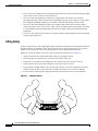
Lifting Safely 2-2
Safety with Electricity 2-3
Preventing Electrostatic Discharge Damage
2-3
Site Requirements 2-4
AC and DC Power 2-4
Plant Wiring 2-4
Interference Considerations 2-5
Distance Limitations and Interface Specifications 2-5
Equipment Racks 2-6
Site Environment 2-8
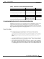
Preventive Site Configuration: Maintaining Normal Operation
General Precautions 2-9
Power Considerations 2-10
Tools for Installation
2-10
Initial Configuration Information
2-11
Cisco 7204 Installation Checklist
2-11
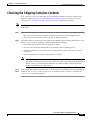
Checking the Shipping Container Contents
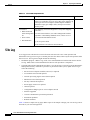
Site Log
CHAPTER
3
2-9
2-13
2-14
Installing the Cisco 7204
3-1
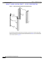
Rack-Mounting the Cisco 7204 3-1
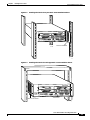
Installing the Brackets on the Chassis 3-5
Installing the Brackets on the Front of the Chassis 3-6
Installing Brackets on the Rear of the Chassis 3-7
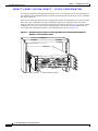
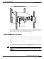
Installing the Chassis in the Rack 3-8
General Installation
3-9
Providing a Chassis Ground Connection for the Router Chassis
Connecting Port Adapter Cables
3-11
3-13
Connecting I/O Controller Cables 3-13
Console and Auxiliary Port Connection Equipment
3-14
Cisco 7204 Installation and Configuration Guide
iv
OL-5101-02
Contents
Console Port Signals 3-15
Auxiliary Port Signals 3-16
Fast Ethernet Connection Equipment 3-16
Fast Ethernet MII Connection Equipment 3-16
Fast Ethernet RJ-45 Connection Equipment 3-18
Connecting Power 3-20
Connecting AC-Input Power
Connecting DC-Input Power
Starting the Cisco 7204
CHAPTER
4
3-20
3-21
3-23
Performing a Basic Configuration of the Cisco 7204
Using the Enable Secret and the Enable Password
4-1
4-1
Configuring the Cisco 7204 4-2
Configuring the Cisco 7204 Using AutoInstall 4-2
Configuring the Cisco 7204 Manually Using the Setup Facility 4-4
Configuring Global Parameters 4-4
Configuring Interfaces 4-7
Configuring the Cisco 7204 Using Configuration Mode 4-10
Saving Your Settings to NVRAM 4-10
Checking Your Settings and Reviewing Your Configuration Changes
Implementing Other Configuration Tasks
What Do I Do Now?
CHAPTER
5
4-11
4-11
4-11
Troubleshooting the Installation
5-1
Troubleshooting Overview 5-2
Problem Solving with Subsystems 5-3
Identifying Startup Problems 5-3
Troubleshooting the Power Subsystem
5-5
Troubleshooting the Processor Subsystem 5-6
Troubleshooting the I/O Controller 5-6
Troubleshooting the Network Processing Engine 5-6
Troubleshooting the Port Adapters and Service Adapters
Troubleshooting the Cooling Subsystem
CHAPTER
6
Maintaining the Cisco 7204
5-7
5-7
6-1
Viewing Your System Configuration
6-1
Replacing a Port Adapter or Service Adapter
Installing and Removing a Flash Memory Card
6-3
6-7
Cisco 7204 Installation and Configuration Guide
OL-5101-02
v
Contents
Formatting a New Flash Memory Card
6-8
Copying a Bootable Image onto a Flash Memory Card
6-9
Copying Bootable Images between Flash Memory Cards
Reformatting a Flash Memory Card
6-11
6-12
Replacing or Recovering a Lost Password 6-13
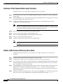
Overview of the Password Recovery Procedure 6-14
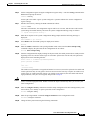
Details of the Password Recovery Procedure 6-14
APPENDIX
A
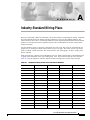
Industry-Standard Wiring Plans
APPENDIX
B
Configuration Register Information
Configuration Bit Meanings
Bits 0–3 B-6
Bit 6 B-7
Bit 7 B-7
Bit 8 B-8
Bit 10 and Bit 14 B-8
Bit 11 and Bit 12 B-8
Bit 13 B-8
Bit 15 B-9
A-1
B-5
B-5
Displaying the Configuration Register While Running Cisco IOS
B-9
Displaying the Configuration Register While Running ROM Monitor
Setting the Configuration Register While Running Cisco IOS
B-9
B-10
Setting the Configuration Register While Running ROM Monitor
B-10
INDEX
Cisco 7204 Installation and Configuration Guide
vi
OL-5101-02
Preface
This section explains the objectives, intended audience, and organization of the Cisco 7204 Installation
and Configuration Guide, and defines the conventions used to convey instructions and information.
Document Objectives
This installation guide explains the initial hardware installation and basic configuration procedures for
the Cisco 7204 router. It contains procedures for unpacking and installing the router hardware, starting
up the router, and creating a basic software configuration file. After completing the installation and basic
configuration procedures covered in this guide, you will then use the appropriate companion
publications to more completely configure your system.
For comprehensive descriptions and examples of software configuration commands and the procedures
for implementing them, refer to the related software configuration and reference documentation listed in
the section “Related Documentation” section on page xiii.
Audience
To use this publication, you should be familiar with Cisco router hardware and cabling, electronic
circuitry and wiring practices, and preferably have experience as an electronic or electromechanical
technician.
Document Organization
This installation guide is organized into the following chapters and appendix.
Cisco 7204 Installation and Configuration Guide
OL-5105-02
vii
Preface
Document Conventions
Chapter
Title
Description
Chapter 1
Product Overview
Chapter 1 describes the physical properties of
the Cisco 7204 and provides a functional
overview of the router.
Chapter 2
Preparing for Installation
Chapter 2 is a preparatory chapter that
describes safety considerations, tools required,
an overview of the installation, and procedures
you should perform before the actual
installation.
Chapter 3
Installing the Cisco 7204
Chapter 3 provides instructions for installing
the hardware and connecting the external
network interface cables.
Chapter 4
Performing a Basic Configuration of the Cisco 7204
Chapter 4 provides simple procedures for
completing a basic system configuration and
for checking and saving this configuration to
system memory.
Chapter 6
Troubleshooting the Installation
Chapter 5 provides guidelines for
troubleshooting the hardware installation.
Chapter 5
Maintaining the Cisco 7204
Chapter 6 provides simple maintenance
procedures that you might need to perform
after you have installed your Cisco 7204.
Appendix A
Industry-Standard Wiring Plans
Appendix A lists the telephone industry
color-code scheme for 25-pair wires including
the pin numbers.
Appendix B
Configuration Register Information
Appendix B provides configuration register
information.
Document Conventions
This publication uses the following conventions:
•
In screen displays, the symbol ^ represents the key labeled Control. For example, the key
combination ^z means hold down the Control key while you press the z key.
Command descriptions use these conventions:
•
Examples that contain system prompts denote interactive sessions, indicating the commands that
you should enter at the prompt. The system prompt indicates the current level of the EXEC
command interpreter. For example, the prompt router> indicates that you should be at the user
level, and the prompt router# indicates that you should be at the privileged level. Access to the
privileged level usually requires a password. Refer to the related software configuration and
reference documentation listed in the “Related Documentation” section on page xiii, for additional
information.
•
Commands and keywords are in boldface font.
•
Arguments for which you supply values are in italic font.
•
Elements in square brackets ([ ]) are optional.
•
Alternative but required keywords are grouped in braces ({ }) and separated by vertical bars (|).
Cisco 7204 Installation and Configuration Guide
viii
OL-5105-02
Preface
Document Conventions
Examples use these conventions:
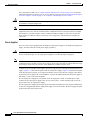
Caution
Note
•
Terminal sessions and sample console screen displays are in
•
Information you enter is in boldface
•
Nonprinting characters, such as passwords, are in angle brackets (< >).
•
Default responses to system prompts are in square brackets ([ ]).
•
Exclamation points (!) at the beginning of a line indicate a comment line.
screen
screen
font.
font.
Means reader be careful. In this situation, you might do something that could result in equipment
damage or loss of data.
Means reader take note. Notes contain helpful suggestions or references to materials not contained in
this manual.
Safety Warnings
Warning
IMPORTANT SAFETY INSTRUCTIONS
This warning symbol means danger. You are in a situation that could cause bodily injury. Before you
work on any equipment, be aware of the hazards involved with electrical circuitry and be familiar
with standard practices for preventing accidents. To see translations of the warnings that appear in
this publication, refer to the translated safety warnings that accompanied this device.
Note: SAVE THESE INSTRUCTIONS
Note: This documentation is to be used in conjunction with the specific product installation guide
that shipped with the product. Please refer to the Installation Guide, Configuration Guide, or other
enclosed additional documentation for further details.
Waarschuwing
BELANGRIJKE VEILIGHEIDSINSTRUCTIES
Dit waarschuwingssymbool betekent gevaar. U verkeert in een situatie die lichamelijk letsel kan
veroorzaken. Voordat u aan enige apparatuur gaat werken, dient u zich bewust te zijn van de bij
elektrische schakelingen betrokken risico's en dient u op de hoogte te zijn van de standaard
praktijken om ongelukken te voorkomen. Voor een vertaling van de waarschuwingen die in deze
publicatie verschijnen, dient u de vertaalde veiligheidswaarschuwingen te raadplegen die bij dit
apparaat worden geleverd.
Opmerking BEWAAR DEZE INSTRUCTIES.
Opmerking Deze documentatie dient gebruikt te worden in combinatie met de
installatiehandleiding voor het specifieke product die bij het product wordt geleverd. Raadpleeg de
installatiehandleiding, configuratiehandleiding of andere verdere ingesloten documentatie voor
meer informatie.
Cisco 7204 Installation and Configuration Guide
OL-5105-02
ix
Preface
Document Conventions
Varoitus
TÄRKEITÄ TURVALLISUUTEEN LIITTYVIÄ OHJEITA
Tämä varoitusmerkki merkitsee vaaraa. Olet tilanteessa, joka voi johtaa ruumiinvammaan. Ennen
kuin työskentelet minkään laitteiston parissa, ota selvää sähkökytkentöihin liittyvistä vaaroista ja
tavanomaisista onnettomuuksien ehkäisykeinoista. Tässä asiakirjassa esitettyjen varoitusten
käännökset löydät laitteen mukana toimitetuista ohjeista.
Huomautus SÄILYTÄ NÄMÄ OHJEET
Huomautus Tämä asiakirja on tarkoitettu käytettäväksi yhdessä tuotteen mukana tulleen
asennusoppaan kanssa. Katso lisätietoja asennusoppaasta, kokoonpano-oppaasta ja muista
mukana toimitetuista asiakirjoista.
Attention
IMPORTANTES INFORMATIONS DE SÉCURITÉ
Ce symbole d'avertissement indique un danger. Vous vous trouvez dans une situation pouvant causer
des blessures ou des dommages corporels. Avant de travailler sur un équipement, soyez conscient
des dangers posés par les circuits électriques et familiarisez-vous avec les procédures couramment
utilisées pour éviter les accidents. Pour prendre connaissance des traductions d'avertissements
figurant dans cette publication, consultez les consignes de sécurité traduites qui accompagnent cet
appareil.
Remarque CONSERVEZ CES INFORMATIONS
Remarque Cette documentation doit être utilisée avec le guide spécifique d'installation du produit
qui accompagne ce dernier. Veuillez vous reporter au Guide d'installation, au Guide de
configuration, ou à toute autre documentation jointe pour de plus amples renseignements.
Warnung
WICHTIGE SICHERHEITSANWEISUNGEN
Dieses Warnsymbol bedeutet Gefahr. Sie befinden sich in einer Situation, die zu einer
Körperverletzung führen könnte. Bevor Sie mit der Arbeit an irgendeinem Gerät beginnen, seien Sie
sich der mit elektrischen Stromkreisen verbundenen Gefahren und der Standardpraktiken zur
Vermeidung von Unfällen bewusst. Übersetzungen der in dieser Veröffentlichung enthaltenen
Warnhinweise sind im Lieferumfang des Geräts enthalten.
Hinweis BEWAHREN SIE DIESE SICHERHEITSANWEISUNGEN AUF
Hinweis Dieses Handbuch ist zum Gebrauch in Verbindung mit dem Installationshandbuch für Ihr
Gerät bestimmt, das dem Gerät beiliegt. Entnehmen Sie bitte alle weiteren Informationen dem
Handbuch (Installations- oder Konfigurationshandbuch o. Ä.) für Ihr spezifisches Gerät.
Cisco 7204 Installation and Configuration Guide
x
OL-5105-02
Preface
Document Conventions
Avvertenza
IMPORTANTI ISTRUZIONI SULLA SICUREZZA
Questo simbolo di avvertenza indica un pericolo. La situazione potrebbe causare infortuni alle
persone. Prima di intervenire su qualsiasi apparecchiatura, occorre essere al corrente dei pericoli
relativi ai circuiti elettrici e conoscere le procedure standard per la prevenzione di incidenti. Per le
traduzioni delle avvertenze riportate in questo documento, vedere le avvertenze di sicurezza che
accompagnano questo dispositivo.
Nota CONSERVARE QUESTE ISTRUZIONI
Nota La presente documentazione va usata congiuntamente alla guida di installazione specifica
spedita con il prodotto. Per maggiori informazioni, consultare la Guida all'installazione, la Guida
alla configurazione o altra documentazione acclusa.
Advarsel
VIKTIGE SIKKERHETSINSTRUKSJONER
Dette varselssymbolet betyr fare. Du befinner deg i en situasjon som kan forårsake personskade.
Før du utfører arbeid med utstyret, bør du være oppmerksom på farene som er forbundet med
elektriske kretssystemer, og du bør være kjent med vanlig praksis for å unngå ulykker. For å se
oversettelser av advarslene i denne publikasjonen, se de oversatte sikkerhetsvarslene som følger
med denne enheten.
Merk TA VARE PÅ DISSE INSTRUKSJONENE
Merk Denne dokumentasjonen skal brukes i forbindelse med den spesifikke
installasjonsveiledningen som fulgte med produktet. Vennligst se installasjonsveiledningen,
konfigureringsveiledningen eller annen vedlagt tilleggsdokumentasjon for detaljer.
Aviso
INSTRUÇÕES IMPORTANTES DE SEGURANÇA
Este símbolo de aviso significa perigo. O utilizador encontra-se numa situação que poderá ser
causadora de lesões corporais. Antes de iniciar a utilização de qualquer equipamento, tenha em
atenção os perigos envolvidos no manuseamento de circuitos eléctricos e familiarize-se com as
práticas habituais de prevenção de acidentes. Para ver traduções dos avisos incluídos nesta
publicação, consulte os avisos de segurança traduzidos que acompanham este dispositivo.
Nota GUARDE ESTAS INSTRUÇÕES
Nota Esta documentação destina-se a ser utilizada em conjunto com o manual de instalação
incluído com o produto específico. Consulte o manual de instalação, o manual de configuração ou
outra documentação adicional inclusa, para obter mais informações.
¡Advertencia!
INSTRUCCIONES IMPORTANTES DE SEGURIDAD
Este símbolo de aviso indica peligro. Existe riesgo para su integridad física. Antes de manipular
cualquier equipo, considere los riesgos de la corriente eléctrica y familiarícese con los
procedimientos estándar de prevención de accidentes. Vea las traducciones de las advertencias
que acompañan a este dispositivo.
Nota GUARDE ESTAS INSTRUCCIONES
Nota Esta documentación está pensada para ser utilizada con la guía de instalación del producto
que lo acompaña. Si necesita más detalles, consulte la Guía de instalación, la Guía de
configuración o cualquier documentación adicional adjunta.
Cisco 7204 Installation and Configuration Guide
OL-5105-02
xi
Preface
Document Conventions
Varning!
VIKTIGA SÄKERHETSANVISNINGAR
Denna varningssignal signalerar fara. Du befinner dig i en situation som kan leda till personskada.
Innan du utför arbete på någon utrustning måste du vara medveten om farorna med elkretsar och
känna till vanliga förfaranden för att förebygga olyckor. Se översättningarna av de
varningsmeddelanden som finns i denna publikation, och se de översatta säkerhetsvarningarna som
medföljer denna anordning.
OBS! SPARA DESSA ANVISNINGAR
OBS! Denna dokumentation ska användas i samband med den specifika
produktinstallationshandbok som medföljde produkten. Se installationshandboken,
konfigurationshandboken eller annan bifogad ytterligare dokumentation för närmare detaljer.
Cisco 7204 Installation and Configuration Guide
xii
OL-5105-02
Preface
Terms and Acronyms
Terms and Acronyms
To fully understand the content of this installation and configuration guide, you should be familiar with
the following terms and acronyms:
•
DCE—Data communications equipment
•
DMA—Direct memory access
•
DRAM—Dynamic random-access memory
•
DTE—Data terminal equipment
•
EPROM—Erasable programmable read-only memory
•
FRU—Field-replaceable unit (router components that do not require replacement by a
Cisco-certified service provider)
•
Gbps—Gigabits per second
•
MB—Megabyte
•
NVRAM—Nonvolatile random-access memory
•
OIR—Online insertion and removal
•
PCI—Peripheral component interconnect
•
PCMCIA—Personal Computer Memory Card International Association
•
RFI—Radio frequency interference
•
RISC—Reduced instruction set computing
•
SIMM—Single in-line memory module
•
SNMP—Simple Network Management Protocol
•
SRAM—Static random-access memory
•
TFTP—Trivial File Transfer Protocol
Related Documentation
Your Cisco 7204 router and the Cisco IOS software running on it contain extensive features and
functionality, which are documented in the following resources:
•
Cisco 7200 Series Routers Documentation Roadmap at
http://www.cisco.com/univercd/cc/td/doc/product/core/7200vx/ol3512.htm for a list of all Cisco
7200 series routers documentation and troubleshooting tools and information.
•
Cisco 7200 Series Routers Port Adapter Documentation Roadmap at
http://www.cisco.com/univercd/cc/td/doc/product/core/7200vx/ol3530.htm for a list of all Cisco
7200 series routers-supported port adapter documentation.
•
Cisco 7200 Series Routers Troubleshooting Documentation Roadmap at
http://www.cisco.com/univercd/cc/td/doc/product/core/7200vx/ol3518.htm for links to
troubleshooting tools, utilities, and Tech Notes.
Cisco 7204 Installation and Configuration Guide
OL-5105-02
xiii
Preface
Obtaining Documentation
Obtaining Documentation
Cisco documentation and additional literature are available on Cisco.com. Cisco also provides several
ways to obtain technical assistance and other technical resources. These sections explain how to obtain
technical information from Cisco Systems.
Cisco.com
You can access the most current Cisco documentation at this URL:
http://www.cisco.com/univercd/home/home.htm
You can access the Cisco website at this URL:
http://www.cisco.com
You can access international Cisco websites at this URL:
http://www.cisco.com/public/countries_languages.shtml
Ordering Documentation
You can find instructions for ordering documentation at this URL:
http://www.cisco.com/univercd/cc/td/doc/es_inpck/pdi.htm
You can order Cisco documentation in these ways:
•
Registered Cisco.com users (Cisco direct customers) can order Cisco product documentation from
the Ordering tool:
http://www.cisco.com/en/US/partner/ordering/index.shtml
•
Nonregistered Cisco.com users can order documentation through a local account representative by
calling Cisco Systems Corporate Headquarters (California, USA) at 408 526-7208 or, elsewhere in
North America, by calling 800 553-NETS (6387).
Documentation Feedback
You can send comments about technical documentation to [email protected].
You can submit comments by using the response card (if present) behind the front cover of your
document or by writing to the following address:
Cisco Systems
Attn: Customer Document Ordering
170 West Tasman Drive
San Jose, CA 95134-9883
We appreciate your comments.
Cisco 7204 Installation and Configuration Guide
xiv
OL-5105-02
Preface
Obtaining Technical Assistance
Obtaining Technical Assistance
For all customers, partners, resellers, and distributors who hold valid Cisco service contracts, Cisco
Technical Support provides 24-hour-a-day, award-winning technical assistance. The Cisco Technical
Support Website on Cisco.com features extensive online support resources. In addition, Cisco Technical
Assistance Center (TAC) engineers provide telephone support. If you do not hold a valid Cisco service
contract, contact your reseller.
Cisco Technical Support Website
The Cisco Technical Support Website provides online documents and tools for troubleshooting and
resolving technical issues with Cisco products and technologies. The website is available 24 hours a day,
365 days a year at this URL:
http://www.cisco.com/techsupport
Access to all tools on the Cisco Technical Support Website requires a Cisco.com user ID and password.
If you have a valid service contract but do not have a user ID or password, you can register at this URL:
http://tools.cisco.com/RPF/register/register.do
Submitting a Service Request
Using the online TAC Service Request Tool is the fastest way to open S3 and S4 service requests. (S3
and S4 service requests are those in which your network is minimally impaired or for which you require
product information.) After you describe your situation, the TAC Service Request Tool automatically
provides recommended solutions. If your issue is not resolved using the recommended resources, your
service request will be assigned to a Cisco TAC engineer. The TAC Service Request Tool is located at
this URL:
http://www.cisco.com/techsupport/servicerequest
For S1 or S2 service requests or if you do not have Internet access, contact the Cisco TAC by telephone.
(S1 or S2 service requests are those in which your production network is down or severely degraded.)
Cisco TAC engineers are assigned immediately to S1 and S2 service requests to help keep your business
operations running smoothly.
To open a service request by telephone, use one of the following numbers:
Asia-Pacific: +61 2 8446 7411 (Australia: 1 800 805 227)
EMEA: +32 2 704 55 55
USA: 1 800 553 2447
For a complete list of Cisco TAC contacts, go to this URL:
http://www.cisco.com/techsupport/contacts
Definitions of Service Request Severity
To ensure that all service requests are reported in a standard format, Cisco has established severity
definitions.
Severity 1 (S1)—Your network is “down,” or there is a critical impact to your business operations. You
and Cisco will commit all necessary resources around the clock to resolve the situation.
Cisco 7204 Installation and Configuration Guide
OL-5105-02
xv
Preface
Obtaining Additional Publications and Information
Severity 2 (S2)—Operation of an existing network is severely degraded, or significant aspects of your
business operation are negatively affected by inadequate performance of Cisco products. You and Cisco
will commit full-time resources during normal business hours to resolve the situation.
Severity 3 (S3)—Operational performance of your network is impaired, but most business operations
remain functional. You and Cisco will commit resources during normal business hours to restore service
to satisfactory levels.
Severity 4 (S4)—You require information or assistance with Cisco product capabilities, installation, or
configuration. There is little or no effect on your business operations.
Obtaining Additional Publications and Information
Information about Cisco products, technologies, and network solutions is available from various online
and printed sources.
•
Cisco Marketplace provides a variety of Cisco books, reference guides, and logo merchandise. Visit
Cisco Marketplace, the company store, at this URL:
http://www.cisco.com/go/marketplace/
•
The Cisco Product Catalog describes the networking products offered by Cisco Systems, as well as
ordering and customer support services. Access the Cisco Product Catalog at this URL:
http://cisco.com/univercd/cc/td/doc/pcat/
•
Cisco Press publishes a wide range of general networking, training and certification titles. Both new
and experienced users will benefit from these publications. For current Cisco Press titles and other
information, go to Cisco Press at this URL:
http://www.ciscopress.com
•
Packet magazine is the Cisco Systems technical user magazine for maximizing Internet and
networking investments. Each quarter, Packet delivers coverage of the latest industry trends,
technology breakthroughs, and Cisco products and solutions, as well as network deployment and
troubleshooting tips, configuration examples, customer case studies, certification and training
information, and links to scores of in-depth online resources. You can access Packet magazine at this
URL:
http://www.cisco.com/packet
•
iQ Magazine is the quarterly publication from Cisco Systems designed to help growing companies
learn how they can use technology to increase revenue, streamline their business, and expand
services. The publication identifies the challenges facing these companies and the technologies to
help solve them, using real-world case studies and business strategies to help readers make sound
technology investment decisions. You can access iQ Magazine at this URL:
http://www.cisco.com/go/iqmagazine
•
Internet Protocol Journal is a quarterly journal published by Cisco Systems for engineering
professionals involved in designing, developing, and operating public and private internets and
intranets. You can access the Internet Protocol Journal at this URL:
http://www.cisco.com/ipj
•
World-class networking training is available from Cisco. You can view current offerings at
this URL:
http://www.cisco.com/en/US/learning/index.html
Cisco 7204 Installation and Configuration Guide
xvi
OL-5105-02
C H A P T E R
1
Product Overview
This chapter provides physical and functional overviews of the Cisco 7204 router. It contains physical
descriptions of the router hardware and major components, and functional descriptions of
hardware-related features. Descriptions and examples of software commands are included only when
they are necessary for replacing, installing, configuring, or maintaining the router hardware.
The Cisco 7204 is part of the Cisco 7200 series routers, which consists of the 2-slot Cisco 7202, 4-slot
Cisco 7204 and Cisco 7204VXR, and 6-slot Cisco 7206 and Cisco 7206VXR. The Cisco 7204 supports
multiprotocol, multimedia routing and bridging over a wide variety of LAN and WAN interface types.
Network interfaces reside on port adapters that provide the connection between the router’s three
Peripheral Component Interconnect (PCI) buses and external networks. The Cisco 7204 has four slots
(slot 1 through slot 4) for the port adapters, one slot for an Input/Output (I/O) controller, and one slot for
a network processing engine. You can place the port adapters or service adapters in any of the four
available slots.
There are bays for up to two AC-input or DC-input power supplies. The Cisco 7204 will operate with
one power supply. While a second power supply is not required, it allows load sharing and increased
system availability.
Note
The Cisco 7204 does not support a mixture of AC- and DC-input power.
The Cisco 7204 provides the following features:
•
Online insertion and removal (OIR)—Allows you to add, replace, or remove port adapters without
interrupting the system or entering any console commands.
•
Dual hot-swappable, load-sharing power supplies—Provide system power redundancy; if one power
supply or power source fails, the other power supply maintains system power without interruption.
Also, when one power supply is powered off and removed from the router, the second power supply
immediately takes over the router’s power requirements without interrupting normal operation of the
router.
•
Environmental monitoring and reporting functions—Allow you to maintain normal system
operation by resolving adverse environmental conditions before any loss of operation.
•
Downloadable software—Allows you to load new images into Flash memory remotely, without
having to physically access the Cisco 7204 router, for fast, reliable upgrades.
Cisco 7204 Installation and Configuration Guide
OL-5101-02
1-1
Chapter 1
Product Overview
Physical Description
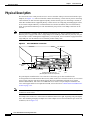
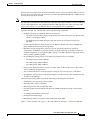
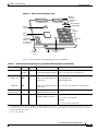
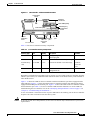
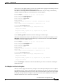
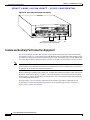
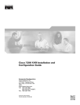
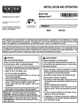
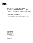
Physical Description
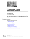
The front of the Cisco 7204 provides access to an I/O controller and up to four network interface port
adapters (see Figure 1-1). The I/O controller contains the following: a local console port for connecting
a data terminal (or data terminal equipment [DTE]) and an auxiliary port for connecting a modem (or
other data communications equipment [DCE]) or other devices for configuring and managing the router;
two Personal Computer Memory Card International Association (PCMCIA) slots for Flash memory
cards; an optional Fast Ethernet port. The Fast Ethernet port provides a 100-Mbps connection to the
network.
Note
The I/O controller is available with or without a Fast Ethernet port. The I/O controller with a Fast
Ethernet port is equipped with either a single MII port or an MII port and an RJ-45 port (only one port
can be used at a time). Although still supported by Cisco Systems, the I/O controller equipped with the
single MII port was discontinued as an orderable product in May 1998.
Figure 1-1
Cisco 7204 Router—Front View
Port adapters
Cisco 7200 SERIES
5
4
K
LIN
0
3
MII
RJ4
EN
AB
LE
D
FAST ETHERNET
TX
2
RX
4
TX
3
RX
TX
RX
2
TX
RX
1
TX
RX
PC Card slots
O PW
K R
M
E II
N
R
E J4
N 5
R
L J4
IN 5
K
0
SL
O
T
EJ
EC
T
1O
Auxiliary
port
Optional Fast Ethernet port
(MII receptacle and RJ-45 receptacle)
H7398
0
R
J45
C
PU
M
II
FAST ETHERNET INPUT/OUTPUT CONTROLLER
EN
AB
LE
D
PC
M
C
IA
I/O controller
FE
SL
O
T
1
Port adapter
lever
R
ES
ET
1
0
7
6
5
4
3
2
1
0
EN
EN
ETHERNET-10BFL
SERIAL-EIA/TIA-232
Console
port
The port adapters installed in the Cisco 7204 are of the same type as those installed on the
second-generation Versatile Interface Processors (VIP2s) in the Cisco 7500 series routers, in Cisco 7000
series routers using the 7000 Series Route Switch Processor (RSP7000) and 7000 series Chassis
Interface (RSP7000CI), and in the Cisco uBR7200 series routers. The port adapters installed in the
Cisco 7204 support OIR. For an explanation of OIR, refer to the section “Online Insertion and Removal”
section on page 1-25.
Note
The I/O controller does not support OIR. You must power down the Cisco 7204 before removing the I/O
controller from the router.
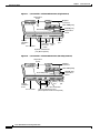
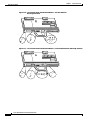
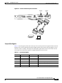
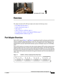
Port adapter slots in the Cisco 7204 router are numbered from left to right, beginning with port adapter
slot 1 and continuing through port adapter slot 4. Port adapter slot 0 is the Fast Ethernet port on the I/O
controller (refer to Figure 1-2).
Cisco 7204 Installation and Configuration Guide
1-2
OL-5101-02
Chapter 1
Product Overview
Physical Description
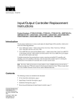
Note
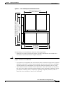
In Figure 1-1 and Figure 1-2, a blank port adapter is installed in slot 3. To ensure adequate airflow across
the port adapters, each port adapter slot must be filled with either a port adapter or a blank port adapter.
Figure 1-2
Port Adapter Slot Numbering
Port adapter slot 4
Port adapter slot 2
Blank port adapter
Cisco 7200 SERIES
FAST ETHERNET
4
K
RJ4
LIN
MII
0
TX
2
TX
RX
4
3
RX
RX
2
1
TX
RX
TX
EN
0
RX
CD
LB
RC
RD
TC
TD
CD
LB
RC
RD
TC
TD
CD
LB
RC
RD
TC
TD
CD
LB
EN
RC
RD
TC
TX
ETHERNET-10BFL
FAST SERIAL
TD
5
D
LE
AB
EN
3
3
2
2
1
0
LINK
1
0
3
EN
AB
LE
D
ETHERNET 10BT
R
ES
ET
0
O PW
K R
1O
R
E J4
N 5
R
L J4
IN 5
K
M
E II
N
0
SL
O
T
EJ
EC
T
PC
M
C
IA
EN
AB
LE
D
H7399
45
R
J-
C
PU
M
II
FE
SL
O
T
1
1
FAST ETHERNET INPUT/OUTPUT CONTROLLER
Port adapter slot 3
Port adapter slot 1
Port adapter slot 0
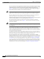
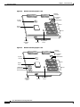
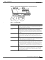
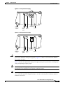
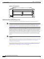
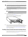
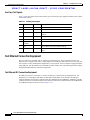
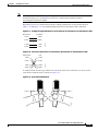
The rear of the Cisco 7204 router provides access to the network processing engine and up to two power
supplies (refer to Figure 1-3).
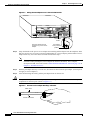
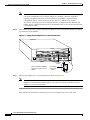
Figure 1-3
Cisco 7204 Router—Rear View
Chassis
grounding
receptacles
Internal fans
AC-input
receptacle
H6423
Power supply
filler plate
NETWORK PROCESSING ENGINE-150
Network processing engine
or network services engine
AC-input
power supply
Power switch
Note
The network processing engine does not support OIR. You must power down the Cisco 7204 before
removing the network processing engine from the router.
The network processing engine has no external connectors or LEDs. There is a handle for removing and
installing the network processing engine and two captive installation screws for securing it to the chassis.
Cisco 7204 Installation and Configuration Guide
OL-5101-02
1-3
Chapter 1
Product Overview
Physical Description
The Cisco 7204 router comes equipped with one 280W AC-input or one 280W DC-input power supply.
A fully configured Cisco 7204 router operates with only one installed power supply; however, a second,
optional power supply of the same type provides hot-swappable, load-sharing, redundant power.
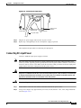
Figure 1-3 shows the rear of a Cisco 7204 router configured with a single AC-input power supply. (A
power supply filler plate is installed over the second power supply bay.)
Caution
Do not mix power supplies in the Cisco 7204. In dual power supply router configurations, both power
supplies must be of the same type (two AC-input power supplies or two DC-input power supplies).
The power supply has the router’s main power switch and either an AC-input power receptacle or a
hardwired DC-input power cable (depending on the type of installed power supply).
Adjacent to the power supply bays there are two chassis ground receptacles that provide a chassis ground
connection for ESD equipment or a two-hole grounding lug (refer to Figure 1-3).
Three internal fans draw cooling air into chassis and across internal components to maintain an
acceptable operating temperature. (Refer to Figure 1-3.) The three fans are enclosed in a tray that is
located in the subchassis.
Caution
To ensure the proper flow of cooling air across the internal components, make sure blank port adapters
are installed in unoccupied port adapter slots, and power supply filler plates are installed in unoccupied
power supply bays.
The I/O controller, port adapters, power supplies, and network processing engine slide into their
respective chassis slots and connect directly to the router’s midplane; there are no internal cables to
connect. The midplane distributes DC power from the power supplies to the I/O controller, port adapters,
fan tray, and network processing engine.
The midplane also identifies OIR of the port adapters, bridges the PCI buses from the port adapters to
packet static random-access memory (SRAM) on the network processing engine, arbitrates traffic across
the PCI buses, and generates the clock signals for the port adapters on each PCI bus.
The Cisco 7204 operates as either a tabletop or rack-mounted unit. A rack-mount kit is standard
equipment included with all Cisco 7204 routers when they are shipped from the factory. The kit provides
the hardware needed to mount the router in a standard 19-inch equipment rack or a 2-post rack. Steps
for installing the Cisco 7204 router in an equipment rack are explained in Chapter 3, “Installing the
Cisco 7204.” If you are not rack-mounting your Cisco 7204, place it on a sturdy tabletop or platform.
A fully configured Cisco 7204, with two installed power supplies and all chassis slots filled, weighs
approximately 50 pounds (22.7 kilograms [kg]). For clearance requirements and rack-mount installation
considerations, refer to the section “Site Environment” in Chapter 2, “Preparing for Installation.”
Cisco 7204 Installation and Configuration Guide
1-4
OL-5101-02
Chapter 1
Product Overview
Physical Description
System Specifications
Table 1-1 lists the Cisco 7204 router physical specifications and power requirements.
Table 1-1
Cisco 7204 Physical Specifications
Description
Specification
Midplane
Two primary PCI buses and one secondary PCI bus with an aggregate bandwidth of 600 Mbps 1
Dimensions (H x W x D)
5.25 in. x 16.8 in. x 17 in. (13.34 cm x 42.67 cm x 43.18 cm)
Weight
Chassis fully configured with a network processing engine, I/O controller, 4 port adapters,
2 power supplies, and a fan tray: ~ 50 lb (22.7 kg)
Heat dissipation
370W (1262 Btu 2)
AC-input voltage rating
100-240 VAC 3 wide input with power factor correction
AC-input current rating
5A4 at 100-240 VAC with the chassis fully configured
AC-input frequency rating
50/60 Hz5
AC-input cable
18 AWG6 three-wire cable, with a three-lead IEC-320 receptacle on the power supply end, and
a country-dependent plug on the power source end
DC-output power
280W maximum (with either a single or a dual power supply configuration)
DC-input voltage rating
–48 VDC7 nominal in North America
–60 VDC nominal in the European Community
DC-input current rating
13A at –48 VDC (370W/–48 VDC = 7.7A typical draw)
8A at –60 VDC (370W/–60 VDC = 6.2A typical draw)
DC voltages supplied and
maximum, steady-state
current ratings
+5.2V @ 30A
+12.2V @ 9A
–12.0V @ 1.5A
+3.5V @ 13A
DC-input cable
In accordance with local and national wiring regulations
Airflow
~80 cfm8
Temperature
32 to 104°F (0 to 40°C) operating; –4 to 149°F (–20 to 65°C) nonoperating
Humidity
10 to 90% noncondensing
1. Mbps = megabits per second.
2. Btu = British thermal units.
3. VAC = volts alternating current.
4. A = amperes.
5. Hz = hertz.
6. AWG = American Wire Gauge.
7. VDC = volts direct current.
8. cfm = cubic feet per minute.
Note
For a chassis footprint, additional dimensions, and clearance requirements for the Cisco 7204 perimeter,
refer to the section “Site Requirements” section on page 2-4 in Chapter 2, “Site Requirements.”
Cisco 7204 Installation and Configuration Guide
OL-5101-02
1-5
Chapter 1
Product Overview
Physical Description
Software Requirements
Below are the recommended minimum software requirements for the Cisco 7204:
Note
•
Cisco IOS Release 11.1(17)CA or a later release of Cisco IOS 11.1 CA
•
Cisco IOS Release 11.2(12)P or a later release of Cisco IOS 11.2 P
•
Cisco IOS Release 11.3(2)T or a later release of Cisco IOS 11.3 T
•
Cisco IOS Release 12.0(3)T or a later release of 12.0 T
For software inforamtion for the Cisco AS5800 Universal Access Server, refer to the Cisco AS5800
Universal Access Server documentation listed on Cisco.com at
http://www.cisco.com/univercd/cc/td/doc/product/access/acs_serv/as5800/index.htm.
Field-Replaceable Units
The Cisco 7204 router is easy to service; all its major components are field replaceable units (FRUs).
The following Cisco 7204 components are FRUs:
•
Network processing engine
•
Input/Output controller
•
Port adapters and service adapters
•
Power supplies
•
Fan tray
•
Chassis
•
PCMCIA Flash Disks and Flash memory cards
•
Rack-mount and cable-management kit
The following sections provide brief overviews of each FRU.
Instructions for removing and replacing FRUs are contained in separate documents. For example, if you
need to replace the I/O controller in your Cisco 7204 router, refer to the Input/Output Controller
Replacement Instructions document. The document is available on Cisco.com.
For ordering information, contact a customer service representative.
Network Processing Engine
The network processing engine maintains and executes the system management functions for the
Cisco 7204 router. The network processing engine also shares the system memory and environmental
monitoring functions with the I/O controller.
Note
Detailed instructions for removing and replacing the network processing engine are contained in the
Network Processing Engine or Network Services Engine Installation and Configuration. This document
is available on Cisco.com.
The network processing engine is available in four versions: the NPE-100, NPE-150, NPE-200, and
NPE-300.
Cisco 7204 Installation and Configuration Guide
1-6
OL-5101-02
Chapter 1
Product Overview
Physical Description
Network processing engines have the same functionality; however, their performance differs because of
the microprocessor type and the type of memory for packet data (SRAM and DRAM, or SDRAM) each
network processing engine provides.
Note
The Cisco 7204 supports all versions of the network processing engine except the NPE-300; therefore,
the NPE-300 is not explained in this publication. (The NPE-300 is keyed so that it can only be installed
in Cisco 7200 VXR routers.) For information about the NPE-300 and its use in the Cisco 7200 VXR
routers, refer to the Cisco 7200 VXR Installation and Configuration Guide publication.
The NPE-100, NPE-150, and NPE-200 consist of the following components:
•
Reduced instruction set computing (RISC) microprocessor
– The NPE-100 and the NPE-150 have an R4700 microprocessor that operates at an internal clock
speed of 150 megahertz (MHz).
– The NPE-200 has an R5000 microprocessor that operates at an internal clock speed of
200 MHz.
•
System controller that uses direct memory access (DMA) to transfer data between DRAM and
packet SRAM on the network processing engine.
•
DRAM for storing routing tables, protocols, network accounting applications, packets of
information in preparation for process switching, and packet buffering for SRAM overflow. The
standard configuration is 32 megabytes (MB), with up to 128 MB available through single in-line
memory module (SIMM) upgrades.
•
Packet SRAM for storing packets of information in preparation for fast switching.
– The NPE-100 does not have SRAM.
– The NPE-150 has 1 MB of SRAM.
– The NPE-200 has 4 MB of SRAM.
•
Unified cache SRAM that functions as the secondary cache for the microprocessor. (The primary
cache is within the microprocessor.)
•
Two environmental sensors for monitoring the cooling air as it leaves the Cisco 7204 chassis.
•
Boot ROM for storing sufficient code for booting the Cisco IOS software. (This component is only
available on the NPE-200.)
The network processing engines perform the following system management functions:
•
Sending and receiving routing protocol updates
•
Managing tables, caches, and buffers
•
Monitoring interface and environmental status
•
Providing Simple Network Management Protocol (SNMP) management and the console/Telnet
interface
•
Accounting and switching of data traffic
•
Booting and reloading images
•
Managing port adapters (recognition and initialization during OIR)
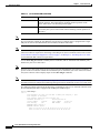
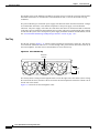
Figure 1-4 shows the NPE-100, Figure 1-5 shows the NPE-150, and Figure 1-6 shows the NPE-200.
Cisco 7204 Installation and Configuration Guide
OL-5101-02
1-7
Chapter 1
Product Overview
Physical Description
Figure 1-4
Network Processing Engine—100
Midplane
connectors
Temperature
sensor
System
controller
DRAM SIMMs
U12
Bank 1
R4700
microprocessor
U4
U25
Bank 0
H8822
U18
NETWORK PROCESSING ENGINE-100
Captive
installation
screw
Figure 1-5
Handle
Temperature
sensor
Network Processing Engine—150
Midplane
connectors
Temperature
sensor
System
controller
DRAM SIMMs
U12
Bank 1
R4700
microprocessor
U4
U25
1-MB SRAM
U700 through U703
U800 through U803
Bank 0
NETWORK PROCESSING ENGINE-150
Captive
installation
screw
Handle
H5999
U18
Temperature
sensor
Cisco 7204 Installation and Configuration Guide
1-8
OL-5101-02
Chapter 1
Product Overview
Physical Description
Figure 1-6
Network Processing Engine—200
Midplane
connectors
Temperature
sensor
Boot ROM U92
DRAM SIMMs
System
controller
U52
Bank 1
U42
R5000
microprocessor
U25
Bank 0
4-MB SRAM
U6, U10, U13,
U14, U28, U29,
U38, and U39
NETWORK PROCESSING ENGINE-200
Captive
installation
screw
Handle
H10310
U11
Temperature
sensor
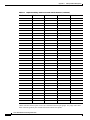
Table 1-1 lists the network processing engine memory components.
Table 1-2
Network Processing Engine Memory Components (NPE-100, NPE-150, and NPE-200)
Memory Type
Size
Quantity
Description
Location
DRAM
32 MB to 2 or 4
128 MB
16- or 32-MB SIMMs (based
Bank 0: U18 and U25 or U11 and U25 1
on maximum DRAM required) Bank 1: U4 and U12 or U42 and U52 2
NPE-150
1 MB
8
8 chips, each being 128K words U700 through U703
U800 through U803
x 9 bits wide
NPE-200
4 MB
8
8 chips, each being 512K words U6, U10, U13, U14, U28, U29, U38, and U39
x 8 bits wide
Boot ROM4
256 KB
(NPE-200 only)
1
PLCC-type integrated circuit
for the ROM monitor program
Unified cache
4
Secondary cache for the R4700 NPE-100 and NPE-150
and R5000 RISC processors
U2, U10, U14, and U26
SRAM3
512 KB
Socket U92
NPE-200
U16, U9, U109, and U107
1. The sockets for bank 0 on the NPE-100 and the NPE-150 are numbered U18 and U25. The same sockets on the NPE-200 are numbered U11 and U25.
2. The sockets for bank 1 on the NPE-100 and the NPE-150 are numbered U4 and U12. The same sockets on the NPE-200 are numbered U42 and U52.
3. The NPE-100 does not have SRAM.
4. ROM = read-only memory.
Cisco 7204 Installation and Configuration Guide
OL-5101-02
1-9
Chapter 1
Product Overview
Physical Description
Note
To prevent DRAM errors and to ensure your system initializes correctly at startup, DRAM bank 0
(socket U18 and U25, or U11 and U25) must contain no fewer than two SIMMs of the same type. You
may also install two SIMMs of the same type in bank 1 (socket U4 and U12, or U42 and U52); however,
bank 0 must always contain the two largest SIMMs.
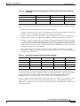
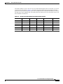
Table 1-3 lists the network processing engine factory-installed DRAM configurations and their product
numbers.
Table 1-3
DRAM SIMM Configurations (NPE-100, NPE-150, and NPE-200)
Total DRAM
DRAM Bank 0
Quantity
DRAM Bank 1
Quantity
Product Number
32 MB
U18 and U25
or
U11 and U25
2 16-MB
SIMMs
U4 and U12 or –
U42 and U52
MEM-NPE-32MB1
64 MB
U18 and U25
or
U11 and U25
2 32-MB
SIMMS
U4 and U12 or –
U42 and U52
MEM-NPE-64MB1
128 MB
U18 and U25
or
U11 and U25
2 32-MB
SIMMs
U4 and U12 or 2 32-MB
U42 and U52 SIMMs
MEM-NPE-128MB1
1. These products are also available as DRAM upgrades. For example, to upgrade a network processing engine from 32 MB to
64 MB of DRAM, order product number MEM-NPE-32MB=. A 16 MB-option (product number MEM-NPE-16MB=), which
consists of two 8-MB SIMMs, is also available from the factory as a DRAM upgrade.
Use the show version command to identify the network processing engine installed in your Cisco 7204
router. The following example shows an installed NPE-150:
Router> show version
Cisco Internetwork Operating System Software
IOS (tm) 7200 Software (C7200-J-M), Released Version 11.1(17)CA
Copyright (c) 1986-1996 by cisco Systems, Inc.
Compiled Sun 04-Aug-96 06:00 by rmontino
Image text-base: 0x60010890, data-base: 0x605F0000
(display text omitted)
cisco 7204 (NPE 150) processor with 12288K/4096K bytes of memory.
R4700 processor, Implementation 33, Revision 1.0 (Level 2 Cache)
Last reset from power-on
Bridging software.
(display text omitted)
Cisco 7204 Installation and Configuration Guide
1-10
OL-5101-02
Chapter 1
Product Overview
Physical Description
Input/Output Controller
The Input/Output controller shares the system memory functions and the environmental monitoring
functions for the Cisco 7204 router with the network processing engine.
Note
Detailed instructions for removing and replacing the I/O controller are contained in the configuration
note Input/Output Controller Replacement Instructions. The configuration note is also available on
Cisco.com.
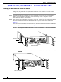
The I/O controller consists of the following components:
Note
•
Dual EIA/TIA-232 channels for local console and auxiliary ports. The console port has full DCE
functionality and a DB-25 port. The auxiliary port has full DTE functionality and a DB-25 plug.
•
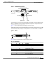
An optional Fast Ethernet port, equipped with either a single MII port (see Figure 1-7) or an MII
port and an RJ-45 port (see Figure 1-8), that is configurable for use at 100 megabits per second
(Mbps) full-duplex or half-duplex (half-duplex is the default). The I/O controller without the Fast
Ethernet port is shown in Figure 1-9.
When you use the I/O controller that is equipped with an MII port and an RJ-45 port, only one port can
be configured for use at a time. Although still supported by Cisco Systems, the I/O controller equipped
with the single MII port was discontinued as an orderable product in May 1998.
•
NVRAM for storing the system configuration and environmental monitoring logs. NVRAM uses
lithium batteries to maintain its contents when disconnected from power.
•
Flash memory SIMM for storing the boot helper image.
•
Two PCMCIA slots for Flash Disks or Flash memory cards, which contain the default Cisco IOS
software image.
•
Boot ROM for storing sufficient code for booting the Cisco IOS software.
•
Two environmental sensors for monitoring the cooling air as it enters and leaves the Cisco 7204
chassis.
Cisco 7204 Installation and Configuration Guide
OL-5101-02
1-11
Chapter 1
Product Overview
Physical Description
Figure 1-7
I/O Controller—with Fast Ethernet Port (Single MII Port)
Temperature
sensor
Midplane
connectors
Flash SIMM [U99]
NVRAM [U41]
Temperature
sensor
Boot ROM [U20]
LE
B
A
LO
T
1
FE
M
FAST ETHERNET INPUT/OUTPUT CONTROLLER
II
H6000
S
N
E
D
M
C
P
C
IA
E
JE
C
T
LO
S
T
LE
B
0
F
Captive
installation
screw
PC Card slots
E
IIA
MN
E EN
K
E
F
LIN 45 E
J R
RU K
P IN
C L
T
E
S
W
P
R
K
O
A
U
X
IO
C
LEDs and Auxiliary
CPU reset
port
button
O
N
S
O
LE
Console
port
Optional Fast Ethernet
port (MII receptacle)
Figure 1-8
I/O Controller—with Fast Ethernet Port (MII and RJ-45 Ports)
Temperature
sensor
Midplane
connectors
Flash SIMM [U99]
NVRAM [U41]
Temperature
sensor
S
LO
T
1
FE
M
FAST ETHERNET INPUT/OUTPUT CONTROLLER
II
R
N
E
D
LE
B
A
J-4
5
C
C
P
M
C
IA
C
JE
E
T
S
Captive
installation
screw
PC Card slots
LO
T
II
M
N
E
0
R
5
J4
N
E
5
J4 K
R
LIN
R
W
P
IO OK
PU
R
ES
ET
A
U
X
C
O
N
S
O
LE
H11293
Boot ROM [U20]
Auxiliary Console
port
port
LEDs CPU reset button
Optional Fast Ethernet port
(MII receptacle and RJ-45 receptacle)
Cisco 7204 Installation and Configuration Guide
1-12
OL-5101-02
Chapter 1
Product Overview
Physical Description
Figure 1-9
I/O Controller—without Fast Ethernet Port
Temperature
sensor
Midplane
connectors
Flash SIMM [U99]
NVRAM [U41]
Temperature
sensor
Boot ROM [U20]
E
N
D
P
C
M
C
IA
E
JE
C
T
S
LO
T
LO
T
INPUT/OUTPUT CONTROLLER
1
0
Captive
installation
screw
PC Card slots
C
P
U
R
E
S
E
T
E
W
O
P K
O
IO
R
A
U
X
C
Auxiliary
LED and
port
CPU reset
button
O
N
S
O
LE
H7400
S
LE
B
A
Console
port
Table 1-3 lists the I/O controller memory components.
Table 1-4
I/O Controller Memory Components
Memory Type
Size
Quantity
Description
Location
Boot ROM
256 KB
1
DIP-type integrated circuit for the ROM U20
monitor program
Flash SIMM
4 MB
1
Contains the default boot helper image
U99
Flash memory
card
8 to 20 MB
Up to 2
Contains the default Cisco IOS image
PCMCIA
slot 0 and
slot 1
NVRAM
128 KB
1
Nonvolatile EPROM for the system
configuration file
U41
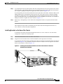
Depending on whether the Fast Ethernet port is present, up to five LEDs on the I/O controller faceplate
indicate system status; two additional LEDs indicate the status of the Flash memory cards installed in
either PCMCIA slot.
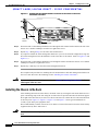
Figure 1-10 shows the LEDs on the I/O controller with the Fast Ethernet port that is equipped with a
single MII port. Figure 1-11 shows the LEDs on the I/O controller with the Fast Ethernet port that is
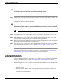
equipped with an MII port and an RJ-45 port. Figure 1-12 shows the LEDs on the I/O controller without
the Fast Ethernet port. Table 1-5 lists I/O controller LEDs and their functions. To use the LEDs for
troubleshooting the I/O controller, refer to the “Identifying Startup Problems” section on page 5-3 in
“Chapter 5, “Troubleshooting the Installation.”.”
A CPU reset button is located next to the IO power OK LED or the auxiliary port on the I/O controller
faceplate. The CPU reset button resets the entire system.
Caution
To prevent system errors and problems, use the CPU reset button only at the direction of your service
representative.
Cisco 7204 Installation and Configuration Guide
OL-5101-02
1-13
Chapter 1
Product Overview
Physical Description
FAST ETHERNET INPUT/OUTPUT CONTROLLER
N
D
LE
B
A
SL
O
T
1
E
H6523
Figure 1-10 I/O Controller LEDs and CPU Reset Button—with Fast Ethernet
Port (Single MII Port)
LE
D
EN F
A E
FE BL
E
LI
N
C
K
PU
R
IO
ES
PO
ET
W
ER
O
K
AB
SL
O
T
0
EN
R
E
A
N
D
LE
B
J-4
5
C
II
R
5
J4
LIN
K
PU
R
ES
ET
FAST ETHERNET INPUT/OUTPUT CONTROLLER
R
W
P
IO OK
AB
LE
D
II
M N
E
5
J4
R N
E
5
J4
R INK
L
R
W
P K
IO O
C
P
U
R
E
S
E
T
SL
O
T
0
EN
SL
O
T
1
M
N
E
5
J4
R
N
E
H11294
Figure 1-11 I/O Controller LEDs and CPU Reset Button—with Fast Ethernet Port (MII and RJ-45 Ports)
Cisco 7204 Installation and Configuration Guide
1-14
OL-5101-02
Chapter 1
Product Overview
Physical Description
Figure 1-12 I/O Controller LEDs and CPU Reset Button—without Fast Ethernet Port
N
A
B
LE
LO
T
1
INPUT/OUTPUT CONTROLLER
D
P
C
M
C
IA
E
JE
C
T
S
T
LO
T
0
P
IO
E
W
O
K
O
R
C
P
U
R
E
S
E
T
A
U
X
C
O
N
S
O
LE
H7401
S
E
1
LO
S
EN
AB
LE
D
T
LO
S
0
IO
P
E
W
O K
O
R
C
P
U
R
E
S
E
T
I
Table 1-5
I/O Controller LEDs
LED
Function
IO Power OK
Indicates that the I/O controller is on and receiving DC power from the router
midplane. This LED comes on during a successful router boot and remains on
during normal operation of the router.
Enabled
Indicates that the network processing engine and the I/O controller are
enabled for operation by the system; however, it does not mean that the Fast
Ethernet port on the I/O controller is functional or enabled. This LED comes
on during a successful router boot and remains on during normal operation of
the router.
FE Enable
Indicates that the Fast Ethernet port on the I/O controller is initialized and
enabled for operation by the system. This LED comes on after the I/O
controller has been enabled and remains on during normal operation of the
router.
FE Link
Indicates that the Fast Ethernet port on the I/O controller has established a
valid link with the network. This LED remains off during normal operation of
the router, unless there is an incoming carrier signal.
MII EN
Indicates that the Fast Ethernet port’s MII ports is initialized and enabled by
the system, and configured for operation. This LED comes on after the I/O
controller has been enabled and the MII port has been configured as the media
type for the Fast Ethernet port (the RJ-45 port is the default media type for
the Fast Ethernet port). This LED remains on during normal operation of the
router.
RJ45 EN
Indicates that the Fast Ethernet port’s RJ-45 port (the default media type for
the Fast Ethernet port) is initialized and enabled by the system. This LED
comes on after the I/O controller has been enabled and remains on during
normal operation of the router.
Cisco 7204 Installation and Configuration Guide
OL-5101-02
1-15
Chapter 1
Product Overview
Physical Description
Table 1-5
I/O Controller LEDs (continued)
LED
Function
RJ45 LINK
Indicates that the Fast Ethernet port’s RJ-45 port has established a valid link
with the network. This LED remains off during normal operation of the
router, unless there is an incoming carrier signal.
Slot 0 Slot 1
Goes on to indicate which PCMCIA slot is in use when either slot is being
accessed by the system. These LEDs remain off during normal operation of
the router.
Note
The I/O controller without the Fast Ethernet port does not have the FE enabled LED and the FE link LED.
The I/O controller without the Fast Ethernet port and the I/O controller that is equipped with a single
MII port do not have the MII enabled, RJ-45 enabled, and RJ-45 link LEDs.
Note
An MII LINK LED is not provided on the I/O controller because the LED is provided on external
transceivers that are required for connecting to the MII port on the I/O controller. Refer to the section
“Fast Ethernet Connection Equipment” section on page 3-16 inChapter 3, “Installing the Cisco 7204”
for Fast Ethernet MII connection requirements.
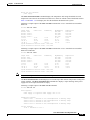
Use the show diag 0 command to identify the I/O controller (with or without the Fast Ethernet port)
installed in your Cisco 7204 router.
Note
Slot 0 in Cisco 7200 series routers is always reserved for the Fast Ethernet port on the I/O controller—if
present. If the I/O controller without the Fast Ethernet port is installed in your Cisco 7200 series router,
the system software will not display output for the show diag 0 command.
Note
Refer to the section ““Port Adapter Slot and Logical Interface Numbering” section on page 1-23 for
information about port adapter slot numbering and logical interface numbering for the Cisco 7204 router.
The following sample output from the show diag 0 command is from a Cisco 7204 I/O controller with
the Fast Ethernet port that is equipped with an MII port and RJ-45 port:
Router> show diag 0
Slot 0:
Fast-ethernet on C7200 I/O with MII or RJ45 port adapter, 1 port
Port adapter is analyzed
Port adapter insertion time 00:10:42 ago
Hardware revision 2.0
Board revision A0
Serial number
3511336
Part number
73-1537-03
Test history
0x0
RMA number
00-00-00
EEPROM format version 1
EEPROM contents (hex):
0x20: 01 14 02 00 00 35 94 28 49 06 01 03 00 00 00 00
0x30: 50 0000 00 FF FF FF FF FF FF FF FF FF FF FF FF
Cisco 7204 Installation and Configuration Guide
1-16
OL-5101-02
Chapter 1
Product Overview
Physical Description
The RJ-45 port is the default media type for the I/O controller that is equipped with an MII port and an
RJ-45 port. Use the media-type command to change the
I/O controller’s media type and the show interfaces command to verify the change. The following
example configures the MII port as the media type for the I/O controller:
Router# config t
Enter configuration commands, one per line. End with CNTL/Z.
Router(config)# int fastethernet 0/0
Router(config-if)# media-type mii
Router(config-if)# no shutdown
Router(config-if)# exit
Router(config)#
%LINEPROTO-5-UPDOWN: Line protocol on Interface FastEthernet0/0, changed
state to up
%LINK-3-UPDOWN: Interface FastEthernet0/0, changed state to up
Router# sh int fastethernet 0/0
FastEthernet0/0 is administratively up, line protocol is up
(display text omitted)
Encapsulation ARPA, loopback not set, keepalive not set, hdx, MII
(display text omitted)
Use the media-type 100X command to return the media type to the RJ-45 port.
The default transmission mode for the Fast Ethernet port on the I/O controller is half-duplex. Use the
full-duplex command to change the Fast Ethernet port’s transmission mode and the show interfaces
command to verify the change as follows:
Router# config t
Enter configuration commands, one per line. End with CNTL/Z.
Router(config)# int fastethernet 0/0
Router(config-if)# full-duplex
Router(config-if)# no shutdown
Router(config-if)# exit
Router(config)#
%LINEPROTO-5-UPDOWN: Line protocol on Interface FastEthernet0/0, changed
state to up
%LINK-3-UPDOWN: Interface FastEthernet0/0, changed state to up
Router# sh int fastethernet 0/0
FastEthernet0/0 is administratively up, line protocol is up
(display text omitted)
Encapsulation ARPA, loopback not set, keepalive not set, fdx, 100BaseTX
(display text omitted)
Use the no full-duplex command to return the Fast Ethernet port on the I/O controller to half-duplex
transmission mode.
Port Adapters and Service Adapters
The Cisco 7204 is shipped from the factory with up to four installed port adapters and service adapters.
Port adapters provide a variety of network media types (based on your order) for the router and service
adapters provide hardware-based services (such as data compression and encryption) for the port adapter
media types. The port and service adapters connect directly to the router’s midplane. Port and service
adapters installed in the Cisco 7204 router support OIR.
Cisco 7204 Installation and Configuration Guide
OL-5101-02
1-17
Chapter 1
Product Overview
Physical Description
For a description of OIR, refer to “Online Insertion and Removal” section on page 1-25. For general
instructions about how to replace a port or service adapter, refer to the section “Replacing a Port Adapter
or Service Adapter” section on page 6-3 in “Chapter 6, “Maintaining the Cisco 7204.”
Caution
Note
To ensure adequate airflow across the router’s port adapters, a port adapter or a blank port adapter must
be installed in each port adapter slot.
Detailed instructions for removing, replacing, and configuring the port and service adapter types
supported by the Cisco 7206 are contained in the configuration note for each port and service adapter.
For example, if you plan to replace a PA-A3 enhanced ATM port adapter in your Cisco 7206 router,
PA-A3 Enhanced ATM Port Adapter Installation and Configuration. This document is available on
Cisco.com.
Power Supplies
The Cisco 7204 comes equipped with one 280W AC-input power supply or one 280W DC-input power
supply. You must order the second power supply separately.
Caution
Do not mix power supplies in the Cisco 7204. In dual power supply configurations, both power supplies
must be of the same type (two AC-input power supplies or two DC-input power supplies).
Note
Detailed instructions for handling and replacing the Cisco 7204 power supplies are contained in the
configuration notes 280-Watt AC-Input Power Supply Replacement Instructions and 280-Watt DC-Input
Power Supply Replacement Instructions. This document is available on Cisco.com.
A handle on the AC and DC power supplies provides a grip point for removing and replacing the power
supply. (Figure 1-13 shows the faceplate of the AC-input power supply. Figure 1-14 shows the faceplate
of the DC-input power supply.) Two captive installation screws secure the power supply to the chassis
and seat the power supply in the router midplane. A power OK LED indicates that the power supply is
delivering +5 VDC to the router midplane.
The AC-input power supply has a receptacle for an AC-input power cable. A modular power cable
connects the AC-input power supply to the site AC power source. A cable-retention clip secures the
power cable to the AC-input power supply.
The DC-input power supply has DC-input power leads that are hardwired to a DC-input terminal block.
A cable tie is shipped with each DC-input power supply to secure the leads to the power supply faceplate
and provide strain relief for the leads.
Cisco 7204 Installation and Configuration Guide
1-18
OL-5101-02
Chapter 1
Product Overview
Physical Description
H6432
Figure 1-13 AC-Input Power Supply
Captive
installation
screw
OK LED
Power
Power
switch
switch
guard
AC-input
receptacle
Handle
H8618
Figure 1-14 DC-Input Power Supply
Captive
installation
screw
Caution
DC-input
OK LED
receptacle
Power
Power
switch
switch
guard
Handle
To ensure adequate airflow across the router’s power supplies, a power supply or a power supply filler
plate must be installed in each power supply bay. Figure 1-13 shows a Cisco 7204 with an installed
power supply filler plate.
Table 1-1 lists the AC-input and DC-input power supply system power specifications, including input
voltage and operating frequency ranges.
Note
Each AC-input power supply operating at 120 VAC requires a minimum of 5A service. We recommend
powering the Cisco 7204 from a 15A receptacle at the power source.
Note
Each DC-input power supply operating at –48 VDC in North America requires a minimum of 13A
service. Each DC-input power supply operating at –60 VDC in the European Community requires a
minimum of 8A service.
Cisco 7204 Installation and Configuration Guide
OL-5101-02
1-19
Chapter 1
Product Overview
Physical Description
This product relies on the building’s installation for short-circuit (overcurrent) protection. Ensure that a
listed and certified fuse or circuit breaker, 20A minimum 60 VDC, is used on all current-carrying
conductors.
The power OK LED goes off and the power supply will shut itself down when the internal DC voltages
exceed allowable tolerances or the internal temperature of the power supply exceeds allowable
tolerances. The power supply will remain in a shut down state until it is disconnected and reconnected
to the source power, and then restarted with the power switch. The power switch turns the power supply
on and starts the system. For a description of power-supply shutdown conditions and thresholds, refer to
the ““Environmental Monitoring and Reporting Functions” section on page 1-26”.
Fan Tray
The fan tray, shown in Figure 1-15, consists of three fans that are enclosed in a metal case. The fan tray
is located in the subchassis and receives –12 VDC through a DC power harness that connects directly to
the router midplane. You must remove the subchassis to access the fan tray.
Figure 1-15 Cisco 7204 Fan Tray
DC power
harness
H6430
Alignment
tabs
The fan tray draws cooling air in through the intake vent on the right side of the chassis (when viewing
the router from the front), and moves the air across the internal components and out the exhaust vent on
the left side of the chassis.
Figure 1-16 shows the air flow through the router.
Cisco 7204 Installation and Configuration Guide
1-20
OL-5101-02
Chapter 1
Product Overview
Physical Description
Figure 1-16 Internal Air Flow—Top View
Power supply end
Inlet
airflow
H6237
Exhaust
air
Port adapter end
The left and right sides of the chassis must remain unobstructed to ensure adequate air flow and prevent
overheating inside the chassis; we recommend at least three inches of clearance. (See the “Site
Requirements” section on page 2-4 in the chapter Chapter 2, “Preparing for Installation.”)
Temperature sensors on the network processing engine and I/O controller monitor the internal air
temperature and send warning messages when the internal air temperature approaches a specified
threshold. If the internal temperature exceeds the specified threshold, the system environmental monitor
shuts down all internal power to prevent equipment damage from excessive heat.
Chassis
The Cisco 7204 chassis, shown in Figure 1-17, has four slots for the port adapters, one slot for the I/O
controller, and one bay for the subchassis. To replace the chassis, you must remove all of the internal
components, including the subchassis.
Note
Because you must remove all the internal components when replacing the chassis, refer to the
configuration notes that explain how to remove and replace the internal components. These documents
are available on Cisco.com.
Cisco 7204 Installation and Configuration Guide
OL-5101-02
1-21
Chapter 1
Product Overview
Physical Description
Figure 1-17 Cisco 7204 Chassis
Cisco 7200 SERIES
4
3
H7402
0
2
5
PCMCIA Flash Disks and Flash Memory Cards
The Cisco 7204 supports up to two installed PCMCIA Flash Disks or two Flash memory cards.
Note
To avoid potential problems when inserting spare Flash Disks or Flash memory cards in your
Cisco 7204, we recommend that you reformat all of your Flash Disks or Flash memory cards on a
Cisco 7204 running one of the recommended Cisco IOS software releases. The chapter Chapter 6,
“Maintaining the Cisco 7204” contains instructions that explain how to reformat a Flash memory card.
Flash memory (Flash Disks or cards and the Flash SIMM on the I/O controller) allows you to remotely
load and store multiple system and boot helper images. You can download a new image over the network
and then add the new image to Flash memory or replace existing files. You can also transfer images
between Flash Disks or cards and the onboard Flash memory SIMM. You can then boot the router either
manually or automatically from any of the stored images. Flash memory can also function as a TFTP
server to allow other routers to boot remotely from stored images or copy them into their own Flash
memory.
Note
For procedures that explain the use of the PCMCIA Flash Disk, refer to the Using the Flash Disk
document .
For procedures that explain how to replace main, Flash, and ROM monitor memory in Cisco 7200 series
routers, refer to the Memory Replacement Instructions for the Network Processing Engine and
Input/Output Controller document.
The preceding documents are available on Cisco.com. Instructions for installing and removing a Flash
memory card are also contained in the “Installing and Removing a Flash Memory Card” section on
page 6-7 in Chapter 6, “Maintaining the Cisco 7204” of this guide.
Cisco 7204 Installation and Configuration Guide
1-22
OL-5101-02
Chapter 1
Product Overview
Functional Overview
Table 1-6 lists the Flash memory card options supported by the Cisco 7204.
Table 1-6
Flash Memory Card Options
Memory Size
Product Number
16 MB
MEM-I/O-FLC16M1
20 MB
MEM-I/O-FLC20M1
1. These products are also available as Flash card upgrades. To order an upgrade, add an equal sign (=) after the product number,
for example, MEM-I/O-FLC16M=.
Table 1-7 lists the Flash Disk options supported by the Cisco 7204.
Table 1-7
Flash Disk Options
Memory Size
Product Number
40 MB
MEM-I/O-FLD40M1
110 MB
MEM-I/O-FLD110M1
1. These products are also available as Flash Disk upgrades. To order an upgrade, add an equal sign (=) after the product number,
for example, MEM-I/O-FLD110M=.
Rack-Mount and Cable-Management Kit
The rack-mount and cable-management kit for the Cisco 7204 consists of rack-mount and
cable-management brackets that are designed for mounting your router in 19-inch, 4-post or 2-post
equipment racks and for relieving strain on port adapter interface cables that are installed on port
adapters in the router. The kit is shipped with each Cisco 7204 and is also available as a single FRU.
For detailed instructions about how to install the rack-mount and cable-management brackets on your
Cisco 7204, refer to the “Rack-Mounting the Cisco 7204” section on page 3-1” and the “General
Installation” section on page 3-9” in Chapter 3, “Installing the Cisco 7204.”
Functional Overview
This section provides a functional overview of the Cisco 7204. It describes the numbering and
addressing of the port adapters for the router, the environmental monitoring and reporting functions, and
online insertion and removal (OIR). These descriptions will help you become familiar with the
capabilities of the Cisco 7204 router.
Port Adapter Slot and Logical Interface Numbering
In the Cisco 7204, the port adapter slot number is the chassis slot in which a port or service adapter is
installed, while the logical interface number is the physical location of the interface port on a port
adapter (service adapters do not have interface ports). Port adapter slots are numbered from 1 through 4;
port adapter slot 0 is reserved for the optional Fast Ethernet port on the I/O controller—if present. (Refer
to Figure 1-2 for the numbering scheme of the port adapter slots.) The number of logical interfaces
depends on the type of port adapter.
Cisco 7204 Installation and Configuration Guide
OL-5101-02
1-23
Chapter 1
Product Overview
Functional Overview
The Media Access Control (MAC) or hardware address is a standardized data link layer address that is
required for certain network interface types. These addresses are not used by other devices in the
network; they are specific and unique to each port. The Cisco 7204 uses a specific method to assign and
control the MAC addresses of its port adapters. For a description of the MAC-layer address, see the
section “MAC Address” section on page 1-25 in this chapter.
Port adapter slots maintain the same slot number regardless of whether other port or service adapters are
installed or removed. However, when you move a port adapter to a different slot, the port adapter’s slot
number changes to reflect the new slot number.
You can identify port adapter slots by using software commands to display information about a specific
port or service adapter or for all port and service adapters in the Cisco 7204. To display information
about all port adapter slots, use the show interfaces command. To display information about a specific
port adapter slot, use the show interfaces command with the port adapter type and slot number in the
format show interfaces (port adapter type and slot number/port number). If you abbreviate the
command (sh int) and do not specify port adapter type and slot number (or arguments), the system
interprets the command as show interfaces and displays the status of all port adapters and ports.
Following is an example of how the show interfaces command, used without arguments, displays status
information (including the physical port adapter number) for each port adapter in a Cisco 7204.
In the following example, most of the status information for each interface is omitted.
Router# sh int
FastEthernet0/0 is administratively up, line protocol is up
Hardware is DEC21140, address is 0000.0000.0000 (bia 0000.0000.0000)
Internet address is 1.1.1.3
MTU 1500 bytes, BW 100000 Kbit, DLY 100 usec, rely 255/255, load 1/255
(display text omitted)
Fddi1/0 is administratively down, line protocol is down
Hardware is MIF68840_MM, address is 0000.0000.0000 (bia 0000.0000.0000)
Internet address is 1.1.1.0
MTU 4470 bytes, BW 100000 Kbit, DLY 100 usec, rely 255/255, load 1/255
(display text omitted)
Ethernet2/0 is administratively up, line protocol is up
Hardware is AmdP2, address is 0000.0000.0000 (bia 0000.0000.0000)
Internet address is 1.1.1.7
MTU 1500 bytes, BW 100000 Kbit, DLY 1000 usec, rely 255/255, load 1/255
(display text omitted)
You can also use arguments such as the interface type (Ethernet, TokenRing, Fddi, and so forth) and the
port address (slot/port) to display information about a specific interface only.
The following example shows the display for the first port on the Token Ring port adapter in port adapter
slot 3:
Router# sh int tokenring 3/0
TokenRing3/0 is administratively down, line protocol is down
Hardware is IBM2692, address is 0000.0000.0000 (bia 0000.0000.0000)
Internet address is 1.1.1.8
MTU 4464 bytes, BW 1600 Kbit, DLY 630 usec, rely 255/255, load 1/255
Encapsulation SNAP, loopback not set, keepalive set (10 sec)
ARP type: SNAP, ARP Timeout 04:00:00
Ring speed: 16 Mbps
(display text omitted)
For complete descriptions and instructions for the commands used to configure your Cisco 7204, refer
to the Configuration Fundamentals Configuration Guide and Configuration Fundamentals Command
Reference publications, which are available on Cisco.com.
Cisco 7204 Installation and Configuration Guide
1-24
OL-5101-02
Chapter 1
Product Overview
Functional Overview
MAC Address
LAN interfaces (ports) require unique MAC addresses, also known as hardware addresses. Typically, the
MAC address of an interface is stored on a memory component that resides directly on the interface
circuitry; however, the OIR feature requires a different method. For a description of OIR, refer to the
section ““Online Insertion and Removal” section on page 1-25”.
The OIR feature allows you to remove a port or service adapter and replace it with another identically
configured one. If the new port or service adapter matches the adapter you removed, the system
immediately brings it on line. In order to allow OIR, an address allocator with a unique MAC addresses
is stored in an EEPROM on the router midplane. Each address is reserved for a specific port and slot in
the router regardless of whether a port or service adapter resides in that slot. The MAC addresses are
assigned to the slots in sequence. The first address is assigned to slot 0, and the last address is assigned
to slot 6. This address scheme allows you to remove port and service adapters and insert them into other
routers without causing the MAC addresses to move around the network or be assigned to multiple
devices.
Note that if the MAC addresses were stored on each port or service adapter, OIR would not function
because you could never replace one adapter with an identical one; the MAC addresses would always be
different. Also, each time a port or service adapter was replaced, other devices on the network would
have to update their data structures with the new address, and, if they did not do so quickly enough, could
cause the same MAC address to appear in more than one device at the same time.
Note
Storing the MAC addresses for every slot in one central location means the addresses stay with the
memory device on which they are stored.
Online Insertion and Removal
All port and service adapters in the Cisco 7204 support online insertion and removal (OIR).This function
allows you to install and replace port and service adapters while the router is operating; you do not need
to notify the software or shut down the system power. This provides a method that is seamless to end
users on the network, maintains all routing information, and ensures session preservation.
The following is a functional description of OIR for background information only; for specific
procedures for installing and replacing a port or service adapter in a Cisco 7204 router, refer to the
configuration note that was shipped with the port or service adapter hardware.
Caution
The network processing engine and the I/O controller are required system components that cannot be
removed if the router is operating. Removing the network processing engine or the I/O controller while
the router is operating will cause the router to shut down or crash, and might damage or destroy memory
files.
Each port and service adapter has a bus connector that connects it to the router’s midplane. Each
midplane connector has a set of tiered pins in three lengths that send specific signals to the system as
they make contact with the port adapter. The system assesses the signals it receives and the order in
which it receives them to determine if a port or service adapter is being removed or inserted into the
midplane. From these signals, the system determines whether to reinitialize a new interface or shut down
a removed interface. For example, when inserting an port adapter, the longest pins make contact with the
port adapter first, and the shortest pins make contact last. The system recognizes the signals and the
sequence in which it receives them.
Cisco 7204 Installation and Configuration Guide
OL-5101-02
1-25
Chapter 1
Product Overview
Functional Overview
When you remove or insert a port or service adapter in a Cisco 7204 router, the midplane pins send
signals to notify the system, which then performs as follows:
1.
Rapidly scans the midplane for configuration changes.
2.
Initializes all newly inserted port and service adapters, noting any removed port adapter interfaces
and placing them in the administratively shut down state.
3.
Brings all previously configured interfaces on the port adapter back to the state they were in when
they were removed (service adapters do not have interfaces). Any newly inserted interfaces are put
in the administratively shut down state, as if they were present (but not configured) at boot time. If
a similar port adapter type is reinserted into a slot, its ports are configured and brought on line up to
the port count of the original port adapter.
Environmental Monitoring and Reporting Functions
Environmental monitoring and reporting functions are controlled by the network processing engine and
allow you to maintain normal system operation by identifying and resolving adverse conditions prior to
loss of operation. The environmental monitoring functions constantly monitor the internal chassis air
temperature and DC supply voltages and currents. Each power supply monitors its own voltage and
temperature and shuts itself down if it detects a critical condition within the power supply. If conditions
reach shutdown thresholds, the system shuts down to avoid equipment damage from excessive heat. The
reporting functions periodically log the values of measured parameters so that you can retrieve them for
analysis later, and the reporting functions display warnings on the console if any of the monitored
parameters exceed defined thresholds.
Environmental Monitoring
The environmental monitoring functions use four sensors, two on the network processing engine and two
on the I/O controller, to monitor the temperature of the cooling air as it moves through the chassis.
Table 1-8 lists the temperature thresholds for the processor-monitored levels of a Cisco 7204 router that
has an installed NPE-100, NPE-150, or NPE-200.
Note
Refer to the Cisco 7200 VXR Installation and Configuration Guide publication for the temperature
thresholds and processor-monitored levels of a Cisco 7200 VXR router that has an installed NPE-300.
The Cisco 7204 does not support the NPE-300.
Table 1-8
Typical Processor-Monitored Temperature Thresholds (NPE-100, NPE-150, and NPE-200)
Parameter
High Warning
High Critical
Shutdown
Chassis inlet
104°F (40°C)
122°F (50°C)
–
Chassis outlet 1
109°F (43°C)
127°F (53°C)
136°F (58°C)
Chassis outlet 2
167°F (75°C)
167°F (75°C)
–
Chassis outlet 3
122°F (50°C)
140°F (60°C)
149°F (65°C)
104°F (40°C)
122°F (50°C)
–
NPE-100 or NPE-200
NPE-150
Chassis inlet
Cisco 7204 Installation and Configuration Guide
1-26
OL-5101-02
Chapter 1
Product Overview
Functional Overview
Table 1-8
Typical Processor-Monitored Temperature Thresholds (NPE-100, NPE-150, and NPE-200)
(continued)
Parameter
High Warning
High Critical
Shutdown
Chassis outlet 1
109°F (43°C)
127°F (53°C)
136°F (58°C)
Chassis outlet 2
167°F (75°C)
167°F (75°C)
–
Chassis outlet 3
131°F (55°C)
149°F (65°C)
158°F (70°C)
Table 1-9 lists the DC power thresholds for the normal, warning, and critical (power supply-monitored)
levels.
•
Normal—All monitored parameters are within normal tolerances.
•
Warning—The system has exceeded a specified threshold. The system will continue to operate, but
operator action is recommended to bring the system back to a normal state.
•
Critical—An out-of-tolerance temperature or voltage condition exists. The system will continue to
operate; however, the system is approaching shutdown. Immediate operator action is required.
•
Shutdown—The processor has detected a temperature condition that could result in physical damage
to system components and has disabled DC power to all internal components. Requires immediate
operator action. All DC power will remain disabled until you toggle the power switch. Before any
shutdown, the system logs the status of monitored parameters in NVRAM so you can retrieve it later
to help determine the cause of the problem.
•
Power supply shutdown—The power supply detected an internal out-of-tolerance overvoltage,
overcurrent, or temperature condition and shut itself down. All DC power will remain disabled until
you toggle the power switch.
Table 1-9
Typical Power Supply-Monitored DC-Voltage Thresholds
Parameter
Low Critical
Low Warning
High Warning
High Critical
+3.45V
+3.26V
+3.34V
+3.55V
+3.63V
+5.15V
+4.86V
+4.99V
+5.31V
+5.43V
+12.15V
+11.39V
+11.67
+12.62V
+12.91V
–11.95V
–9.52V
–10.73
–13.16V
–14.38V
If the air temperature exceeds a defined threshold, the system controller displays warning messages on
the console terminal and, if the temperature exceeds the shutdown threshold, it shuts down the system.
The system stores the present parameter measurements for both temperature and DC voltage in
NVRAM, so that you can retrieve them later as a report of the last shutdown parameters.
The power supplies monitor internal power supply temperature and voltages. A power supply is either
within tolerance or out of tolerance (Critical), as shown in Table 1-9. If an internal power supply
temperature or voltage reaches a critical level, the power supply shuts down without any interaction with
the system processor.
Cisco 7204 Installation and Configuration Guide
OL-5101-02
1-27
Chapter 1
Product Overview
Functional Overview
Reporting Functions
The Cisco 7204 displays warning messages on the console if chassis interface-monitored parameters
exceed a defined threshold. You can also retrieve and display environmental status reports with the show
environment, show environment all, show environment last, and show environment table
commands. Parameters are measured and reporting functions are updated every 60 seconds. A brief
description of each of these commands follows.
Note
Caution
Refer to the Cisco 7200 VXR Installation and Configuration Guide publication for sample outputs of the
show environment, show environment all, show environment last, and show environment table
commands from a Cisco 7200 VXR router that has an installed NPE-300. The Cisco 7204 does not
support the NPE-300.
To prevent overheating the chassis, ensure that your system is drawing cool inlet air. Overtemperature
conditions can occur if the system is drawing in the exhaust air of other equipment. Ensure adequate
clearance around the sides of the chassis so that cooling air can flow through the chassis interior
unimpeded and exhaust air exits the chassis and is not drawn into the inlet vent of other device.
The show environment command display reports the current environmental status of the system. The
report displays parameters that are out of the normal values. No parameters are displayed if the system
status is normal. The example that follows shows the display for a system in which all monitored
parameters are within normal range:
Router# show env
All measured values are normal
If the environmental status is not normal, the system reports the worst-case status level. Following is an
example overvoltage warning:
Router# show env
Warning: +3.45 V measured at +3.83 V
The show environment last command retrieves and displays the NVRAM log, which shows the reason
for the last system shutdown (if the shutdown was related to voltage or temperature) and the
environmental status at that time. Air temperature is measured and displayed, and the DC voltage
supplied by the power supply is also displayed.
Following is sample output of the show env last command:
Router# show env last
Temperature
chassis
chassis
chassis
chassis
readings:
inlet previously measured at
outlet 1 previously measured
outlet 2 previously measured
outlet 3 previously measured
Voltage readings:
+3.45 V previously
+5.2 V previously
+12.2 V previously
-12.2 V previously
measured
measured
measured
measured
at
at
at
at
27C/80F
at 31C/87F
at 37C/98F
at 45C/113F
+3.51 V
+5.19 V
+12.42 V
-12.14 V
Cisco 7204 Installation and Configuration Guide
1-28
OL-5101-02
Chapter 1
Product Overview
Functional Overview
Reason for last shutdown:
power supply
The show environment table command displays the temperature and voltage thresholds for each
temperature sensor and for each monitored status level, which are related to those thresholds listed in
Table 1-8 and Table 1-9. The display also lists the shutdown threshold for the system.
Following is sample output of the show env table command for a Cisco 7204 that has an installed
NPE-150:
Router# show env table
Sample Point
LowCritical
LowWarning
chassis inlet
chassis outlet 1
chassis outlet 2
chassis outlet 3
+3.45 V
+3.26
+3.34
+5.15 V
+4.86
+4.99
+12.15 V
+11.39
+11.67
-11.95 V
-9.52
-10.73
System shutdown for chassis outlet 1 58C/136F
System shutdown for chassis outlet 3 70C/158F
HighWarning
40C/104F
43C/109F
75C/167F
55C/131F
+3.55
+5.31
+12.62
-13.16
HighCritical
50C/122F
53C/127F
75C/167F
65C/149F
+3.63
+5.43
+12.91
-14.38
Following is sample output of the show env table command for a Cisco 7204 that has an installed
NPE-100 or NPE-200:
Router# show env table
Sample Point
LowCritical
LowWarning
chassis inlet
chassis outlet 1
chassis outlet 2
chassis outlet 3
+3.45 V
+3.26
+3.34
+5.15 V
+4.86
+4.99
+12.15 V
+11.39
+11.67
-11.95 V
-9.52
-10.73
System shutdown for chassis outlet 1 58C/136F
System shutdown for chassis outlet 3 65C/149F
Note
HighWarning
40C/104F
43C/109F
75C/167F
50C/122F
+3.55
+5.31
+12.62
-13.16
HighCritical
50C/122F
53C/127F
75C/167F
60C/140F
+3.63
+5.43
+12.91
-14.38
Temperature ranges and values are subject to change.
The show environment all command displays an extended report that includes temperature readings and
voltage readings. The show environment all command also displays a report showing which power
supply slots are occupied and which are empty.
Following is sample output of the show env all command:
Router# show env all
Power Supplies:
Power supply 1 is Zytek AC Power Supply. Unit is on.
Power supply 2 is Zytek AC Power Supply. Unit is on.
Temperature
chassis
chassis
chassis
chassis
readings:
inlet
measured
outlet 1 measured
outlet 2 measured
outlet 3 measured
at
at
at
at
47C/116F:Temperature in Warning range!
49C/120F:Temperature in Warning range!
55C/131F
58C/136F:Temperature in Warning range!
Voltage readings:
+3.45 V measured at +3.51 V
Cisco 7204 Installation and Configuration Guide
OL-5101-02
1-29
Chapter 1
Product Overview
Functional Overview
+5.2 V measured at +5.19 V
+12.2 V measured at +12.42 V
-12.2 V measured at -12.14 V
Fan Failures
When the system power is on, all three fans should be operational. The system will continue to operate
if a fan fails; however, if the air temperature exceeds a defined threshold, the system controller displays
warning messages on the console terminal and, if the temperature exceeds the shut down threshold, it
shuts down the system.
If the system does shutdown because the temperature exceeded the shutdown threshold, the system will
display the following message on the console screen and in the environment display when the system
restarts:
Queued messages:
%ENVM-1-SHUTDOWN: Environmental Monitor initiated shutdown
For complete descriptions and instructions of the environmental monitor commands, refer to the
Configuration Fundamentals Configuration Guide and Configuration Fundamentals Command
Reference publications, which are available on Cisco.com.
Cisco 7204 Installation and Configuration Guide
1-30
OL-5101-02
C H A P T E R
2
Preparing for Installation
This chapter describes the equipment and site requirements for installing the Cisco 7204. The chapter
contains the following sections:
•
Safety Recommendations, page 2-1
•
Site Requirements, page 2-4
•
Tools for Installation, page 2-10
•
Initial Configuration Information, page 2-11
•
Cisco 7204 Installation Checklist, page 2-11
•
Checking the Shipping Container Contents, page 2-13
•
Site Log, page 2-14
Before installing your Cisco 7204 you should consider the power and cabling requirements that must be
in place at your installation site, the equipment you will need to install the router, and the environmental
conditions your installation site must meet to maintain normal operation. This chapter guides you
through the process of preparing for your router installation.
Safety Recommendations
The following guidelines will help to ensure your safety and protect the equipment. This list does not
cover all potentially hazardous situations, so be alert.
•
The installation of your Cisco 7204 should be in compliance with national and local electrical codes.
In the United States, National Fire Protection Association (NFPA) 70, United States National
Electrical Code. In Canada, Canadian Electrical Code, part I, CC22.1. In other countries,
International Electrotechnical Commission (IEC) 364, part 1 through part 7.
•
Review the safety warnings listed in the document Regulatory Compliance and Safety Information
for the Cisco 7200 Series Routers that accompanied your Cisco 7204, before installing, configuring,
or maintaining the router.
•
Never attempt to lift an object that might be too heavy for you to lift by yourself.
•
Always turn all power supplies off (O) and unplug all power cables before opening the chassis.
•
Always unplug the power cable before installing or removing a chassis.
•
Keep the chassis area clear and dust free during and after installation.
•
Keep tools and chassis components away from walk areas.
Cisco 7204 Installation and Configuration Guide
OL-5101-02
2-1
Chapter 2
Preparing for Installation
Safety Recommendations
•
Do not wear loose clothing, jewelry (including rings and chains), or other items that could get caught
in the chassis. Fasten your tie or scarf and sleeves.
•
The Cisco 7204 with installed AC-input power supplies ships with a three-wire electrical
grounding-type plug, which will only fit into a grounding-type power outlet. This is a safety feature.
The equipment grounding should be in accordance with local and national electrical codes.
•
The Cisco 7204 with installed DC-input power supplies ships without the necessary wiring to
connect the router to a DC power source. Input, return, and earth (ground) wiring must be provided
by the installation site and installed and protected in accordance with local and national wiring
regulations.
•
The Cisco 7204 operates safely when it is used in accordance with its marked electrical ratings and
product usage instructions.
Lifting Safely
A fully configured Cisco 7204 weighs approximately 50 pounds. The chassis is not intended to be moved
frequently. Before you install the router, ensure that your site is properly prepared so you can avoid
having to move the chassis later to accommodate power sources and network connections.
Whenever you lift the chassis or any heavy object, follow these guidelines (see Figure 2-1):
•
Always disconnect all external cables before lifting or moving the chassis.
•
Do not attempt to lift the chassis by yourself; have someone assist you.
•
Ensure that your footing is solid, and balance the weight of the object between your feet.
•
Lift the chassis slowly; never move suddenly or twist your body as you lift.
•
Keep your back straight and lift with your legs, not your back. If you must bend down to lift the
chassis, bend at the knees, not at the waist, to reduce the strain on your lower back muscles.
•
Lift the chassis from the bottom; grasp the underside of the chassis exterior with both hands.
Figure 2-1
Lifting the Chassis
RJ4
5
MII
0
LIN
K
BLE
D
FAST ETHERNET
ENA
2
3
3
2
1
LINK
1
0
0
ENAB
LED
Cisco 7200 SERIES
ETHERNET 10BT
RJ
K
I
MI LIN
45
FAST ETHERNET MEDIA ADAPTER
D
LE
AB
EN
H7403
0
CD
LB
RC
RD
TC
TD
CD
LB
RC
RD
TC
TD
CD
LB
RC
RD
TC
TD
CD
LB
RC
RD
TC
TD
EN
FAST SERIAL
Cisco 7204 Installation and Configuration Guide
2-2
OL-5101-02
Chapter 2
Preparing for Installation
Safety Recommendations
Safety with Electricity
The port adapters and power supplies are designed to be removed and replaced while the system is
operating without presenting an electrical hazard or damage to the system. However, you must power
down the system before removing or replacing the I/O controller and network processing engine.
Follow these basic guidelines when working with any electrical equipment:
•
Before beginning any procedures requiring access to the chassis interior, locate the emergency
power-off switch for the room in which you are working.
•
Disconnect all power and external cables before installing or removing a chassis.
•
Do not work alone when potentially hazardous conditions exist.
•
Never assume that power has been disconnected from a circuit; always check.
•
Do not perform any action that creates a potential hazard to people or makes the equipment unsafe.
•
Never install equipment that appears damaged.
•
Carefully examine your work area for possible hazards such as moist floors, ungrounded power
extension cables, and missing safety grounds.
In addition, use the guidelines that follow when working with any equipment that is disconnected from
a power source, but still connected to telephone wiring or other network cabling.
•
Never install telephone wiring during a lightning storm.
•
Never install telephone jacks in wet locations unless the jack is specifically designed for wet
locations.
•
Never touch uninsulated telephone wires or terminals unless the telephone line has been
disconnected at the network interface.
•
Use caution when installing or modifying telephone lines.
Preventing Electrostatic Discharge Damage
Electrostatic discharge (ESD) damage, which occurs when electronic cards or components are
improperly handled, can result in complete or intermittent system failures. The network processing
engine, I/O controller, and each port adapter consists of a printed circuit board that is fixed in a metal
carrier. Electromagnetic interference (EMI) shielding, connectors, and a handle are integral components
of the carrier. Although the carrier helps protect the boards, use an antistatic strap whenever handling
the network processing engine, I/O controller, and port adapters. Handle the carriers by the handle and
the carrier edges only; never touch the boards or connector pins.
Caution
Always tighten the captive installation screws on the network processing engine and I/O controller. (See
Figure 1-4 and Figure 1-9.) These screws prevent accidental removal, provide proper grounding for the
system, and help ensure that the bus connectors are properly seated in the midplane.
Following are guidelines for preventing ESD damage:
•
Always use an ESD wrist strap or ankle strap and ensure that it makes good skin contact.
•
When handling a removed network processing engine, I/O controller, or port adapter, make sure the
equipment end of your ESD strap is attached to an unfinished chassis surface of the router; do not
touch the printed circuit board, and avoid contact between the printed circuit board and your
Cisco 7204 Installation and Configuration Guide
OL-5101-02
2-3
Chapter 2
Preparing for Installation
Site Requirements
clothing. Always place the network processing engine, I/O controller, or port adapter component
side up on an antistatic surface or in a static shielding bag. If you are returning the item to the
factory, immediately place it in a static shielding bag.
Caution
•
Ensure the I/O controller and network processing engine are fully inserted in their respective chassis
slots and their captive installation screws are tightened. The captive installation screws prevent
accidental removal, provide proper grounding for the system, and help ensure that the bus
connectors are seated in the midplane.
•
Ensure that each port adapter is fully inserted in its chassis slot and the respective port adapter lever
is in the locked position.
For safety, periodically check the resistance value of the antistatic strap. The measurement should be
between 1 and 10 megohms.
Site Requirements
The environmental monitoring functionality in the Cisco 7204 protects the system and components from
potential damage from overvoltage and overtemperature conditions. To assure normal operation and
avoid unnecessary maintenance, plan your site configuration and prepare your site before installation.
After installation, make sure the site maintains an ambient temperature of 32°F through 104°F (0°C
through 40°C), and keep the area around the chassis as free from dust as is practical.
The following sections address the site environment requirements for the Cisco 7204.
AC and DC Power
The AC-input power supply uses a power factor corrector that allows the Cisco 7204 to operate on input
voltage and frequency within the ranges of 100 to 240 VAC and 50/60 Hz.
Note
We recommend attaching dual power supplies to independent power sources for full redundancy. We also
recommend an uninterruptable power source to protect against power failures at your site. Each
AC-input power supply operating at 120 VAC requires a minimum of 5A service. We recommend
powering the Cisco 7204 from a 15A receptacle at the power source.
The DC-input power supply allows the Cisco 7204 router to operate at –48 VDC nominal in North
America and –60 VDC in Europe.
Refer to Table 1-1 in “Chapter 1, “Product Overview”” for system power specifications, including input
voltage and operating frequency ranges.
Plant Wiring
Following are guidelines for setting up the plant wiring and cabling at your site. When planning the
location of the new system, consider the distance limitations for signaling, EMI, and connector
compatibility, as described in the following sections.
Cisco 7204 Installation and Configuration Guide
2-4
OL-5101-02
Chapter 2
Preparing for Installation
Site Requirements
Interference Considerations
When wires are run for any significant distance in an electromagnetic field, interference can occur
between the field and the signals on the wires. This fact has two implications for the construction of plant
wiring:
•
Bad wiring practice can result in radio interference emanating from the plant wiring.
•
Strong EMI, especially when it is caused by lightning or radio transmitters, can destroy the signal
drivers and receivers in the Cisco 7204, and can even create an electrical hazard by conducting
power surges through lines and into equipment. (Review the safety warnings in the section “Safety
with Electricity” section on page 2-3”.)
Note
To predict and remedy strong EMI, you may also need to consult experts in radio frequency
interference (RFI).
If you use twisted-pair cable in your plant wiring with a good distribution of grounding conductors, the
plant wiring is unlikely to emit radio interference. If you exceed the recommended distances, use a
high-quality twisted-pair cable with one ground conductor for each data signal when applicable.
Warning
A readily accessible two-poled disconnect device must be incorporated in the fixed wiring.
If wires exceed recommended distances, or if wires pass between buildings, give special consideration
to the effect of a lightning strike in your vicinity. The electromagnetic pulse caused by lightning or other
high-energy phenomena can easily couple enough energy into unshielded conductors to destroy
electronic devices. If you have had problems of this sort in the past, you may want to consult experts in
electrical surge suppression and shielding.
Distance Limitations and Interface Specifications
The size of your networks and the distances between connections depend on the type of signal, the signal
speed, and the transmission media (the type of cabling used to transmit the signals). For example,
standard coaxial cable has a greater channel capacity than twisted-pair cabling. The distance and rate
limits in the following descriptions are the IEEE recommended maximum speeds and distances for
signaling; however, you can usually get good results at speeds and distances far greater than these. For
example, the recommended maximum rate for V.35 is 2 Mbps, but it is commonly used at 4 Mbps
without any problems. If you understand the electrical problems that might arise and can compensate for
them, you should get good results with rates and distances greater than those shown here; however, do
so at your own risk.
Note
We recommend that you do not exceed specified transmission rate and distance limits.
When preparing your site for network connections to the Cisco 7204, you must consider a number of
factors related to each type of interface:
•
The type of cabling required for each type (fiber, thick or thin coaxial, shielded twisted-pair, or
unshielded twisted-pair cabling)
•
Distance limitations for each signal type
•
The specific cables you need to connect each interface
Cisco 7204 Installation and Configuration Guide
OL-5101-02
2-5
Chapter 2
Preparing for Installation
Site Requirements
•
Any additional interface equipment you need, such as transceivers, hubs, switches, modems,
channel service units (CSUs), or data service units (DSUs)
•
Cable pinouts if you plan to build your cables
Before installing the Cisco 7204, have all additional external equipment and cables on hand. The
information listed above is contained in the documentation that is shipped with each port adapter. For
example, if you need ATM distance limitations and pinouts, refer to the configuration note PA-A3
Enhanced ATM Port Adapter Installation and Configuration. This configuration note accompanies each
PA-A3 enhanced ATM port adapter that is shipped from the factory as an installed item in a Cisco 7204
and as a FRU.
For ordering information, contact a customer service representative.
Equipment Racks
The rack-mounting hardware included with the Cisco 7204 is suitable for most 19-inch equipment racks
and telco-type racks. To easily access FRUs while the router is installed in a rack, make certain you have
access to the front and rear of the router.
Before using a particular rack, check for obstructions (such as a power strip) that could impair
rack-mount installation. If a power strip does impair a rear rack-mount installation, remove the power
strip before installing the Cisco 7204 in the rack, then replace it after the chassis is installed. As an
alternative, you can mount the Cisco 7204 on an equipment shelf provided that the rack dimensions
allow you to secure the router to the shelf, and the overall configuration permits safe installation and
access. However, we recommend rack-mounting the Cisco 7204. shows the Cisco 7204 footprint and
outer dimensions.
To use the rack-mounting hardware provided with the Cisco 7204, consider the following guidelines:
•
To mount the router between two posts or rails using the brackets, the inner clearance (the width
between the inner sides of the two posts or rails) must be at least 17 inches (43.18 cm).
•
The height of the chassis is 5.25 inches (13.34 cm).
•
When mounting the router in 4-post or telco-type racks, be sure to use all the screws and brackets
provided to secure the chassis to the rack posts.
Cisco 7204 Installation and Configuration Guide
2-6
OL-5101-02
Chapter 2
Preparing for Installation
Site Requirements
Figure 2-2
Cisco 7204 Footprint and Outer Dimensions
Card cage and I/O
controller width
13.5 in. (34.29 cm)
Chassis width
16.8 in. (42.67 cm)
H6238
Fan tray depth 15.81 in.
(40.16 cm)
Chassis depth 17.0 in. (43.18 cm)
Chassis depth (including cable service loop
and port adapter cables) 26 in. (66.04 cm)
Network processing engine width
13.8 in. (35.05 cm)
When planning your rack installation, consider the following guidelines:
•
Caution
Install the Cisco 7204 in an open rack whenever possible. If installation in an enclosed rack is
unavoidable, ensure that the rack has adequate ventilation.
To prevent chassis overheating, never install the Cisco 7204 in an enclosed rack or room that is not
properly ventilated or air conditioned.
•
If you plan to use an equipment shelf, ensure that the shelf is constructed to support the weight and
dimensions of the chassis. shows the chassis footprint, which you will need if you are designing a
customized shelf. We recommend that you use the rack-mount kit designed for the Cisco 7204.
•
Allow sufficient clearance around the rack for maintenance. If the rack is mobile, you can push it
back near a wall or cabinet for normal operation and pull it out for maintenance (installing or moving
port adapters, connecting cables, or replacing or upgrading components). Otherwise, allow 19
inches (48.3 cm) of clearance to remove Cisco 7204 FRUs.
Cisco 7204 Installation and Configuration Guide
OL-5101-02
2-7
Chapter 2
Preparing for Installation
Site Requirements
•
Maintain a minimum clearance of three inches on the right and left of the chassis for the cooling air
inlet and exhaust ports, respectively. Avoid placing the Cisco 7204 in an overly congested rack or
directly next to another equipment rack; otherwise, the heated exhaust air from other equipment can
enter the inlet air vents and cause an overtemperature condition inside the router.
•
Always install heavier equipment in the lower half of a rack to maintain a low center of gravity and
prevent the rack from falling over.
•
If you use telco-type racks, be sure that the rack is bolted to the floor and secured because in these
types of installations only one end of the chassis mounts to the two rack posts with the brackets.
Ensure that the weight of the chassis does not make the rack unstable.
•
Install and use the cable-management bracket included with the Cisco 7204 to keep cables organized
and out of the way of the port adapters and I/O controller. Consider the equipment and cabling that
is already installed in the rack. Ensure that cables from other equipment will not impair access to
the port adapters, or require you to disconnect cables unnecessarily to perform equipment
maintenance or upgrades.
•
If you are planning to install the cable-management brackets on a Cisco 7204 that you are
rack-mounting from the front, you must install the cable-management brackets and the rack-mount
brackets before you install the chassis in the rack.
•
Provide an adequate chassis ground (earth) connection for your router chassis.
Note
We strongly recommend that you provide a chassis ground connection. Refer to the section
“Providing a Chassis Ground Connection for the Router Chassis” section on page 3-11 in
“Chapter 3, “Installing the Cisco 7204”” for instructions.
In addition to the preceding guidelines, review the precautions for avoiding overtemperature conditions
in the following section “Site Environment.” To properly install the Cisco 7204 chassis in a rack, refer
to the instructions in the “Rack-Mounting the Cisco 7204” section on page 3-1 in Chapter 3, “Installing
the Cisco 7204.”
Site Environment
Table 2-1 lists the operating and nonoperating environmental site requirements. The ranges listed are
those within which the Cisco 7204 will continue to operate; however, a measurement that is approaching
the minimum or maximum of a range indicates a potential problem. You can maintain normal operation
by anticipating and correcting environmental anomalies before they approach a maximum operating
range.
Cisco 7204 Installation and Configuration Guide
2-8
OL-5101-02
Chapter 2
Preparing for Installation
Site Requirements
Table 2-1
Specifications for Operating and Nonoperating Environments
Specification
Minimum
Maximum
Temperature, ambient operating
32°F (0°C)
104°F (40°C)
Temperature, ambient nonoperating and storage
–4°F (–20°C)
149°F (65°C)
Humidity, ambient (noncondensing) operating
10%
90%
Humidity, ambient (noncondensing)
nonoperating and storage
5%
95%
Altitude, operating and nonoperating
Sea level
10,000ft. (3050 m)
Vibration, operating
5–200 Hz, 0.5 g (1 oct./min.)
–
Vibration, nonoperating
5–200 Hz, 1 g (1 oct./min.)
200–500 Hz, 2 g (1 oct./min.)
–
Preventive Site Configuration: Maintaining Normal Operation
Planning a proper location for the Cisco 7204 and the layout of your equipment rack or wiring closet are
essential for successful system operation. Equipment placed too close together or inadequately
ventilated can cause system overtemperature conditions. In addition, chassis panels made inaccessible
by poor equipment placement can make system maintenance difficult. Following are precautions that can
help avoid problems during installation and ongoing operation.
General Precautions
Follow these general precautions when planning your equipment locations and connections:
•
Use the show environment command regularly to check the internal system status. The
environmental monitor continually checks the interior chassis environment; it provides warnings for
high temperature and maximum and minimum voltages and creates reports on any occurrences. If
warning messages are displayed, take immediate action to identify the cause and correct the
problem.
•
We recommend keeping the Cisco 7204 off the floor and out of any area that tends to collect dust.
•
Follow ESD prevention procedures to avoid damage to equipment. Damage from static discharge
can cause immediate or intermittent equipment failure.
•
Ensure that the network processing engine, I/O controller, port adapters, any blank port adapters,
power supplies, and any power supply filler plates are in place and secure. The fans direct cooling
air throughout the chassis interior; a loose component or empty slot can redirect the air flow away
from active components.
Cisco 7204 Installation and Configuration Guide
OL-5101-02
2-9
Chapter 2
Preparing for Installation
Tools for Installation
Power Considerations
Follow these precautions and recommendations when planning power connections to the Cisco 7204:
•
Check the power at your site before installation and periodically after installation to ensure that you
are receiving clean power. Install a power conditioner if necessary.
•
Install proper grounding to avoid damage from lightning and power surges.
Note
The Cisco 7204 installation must comply with all applicable codes and is approved for use
with copper conductors only. The ground bond fastening hardware should be of compatible
material and preclude loosening, deterioration, and electro-chemical corrosion of hardware
and joined material. Attachment of the chassis ground to a central office or other interior
ground system should be made with a 6-AWG, copper ground conductor at a minimum. The
Cisco 7204 chassis employs two threaded M5 chassis grounding receptacles, located on the
rear of the chassis, which are intended to be bonded directly to the central offices or other
interior ground system. The chassis ground requires M5 screws and locking hardware, which
are not included. (For instructions on how to properly ground the chassis, refer to the
“Providing a Chassis Ground Connection for the Router Chassis” section on page 3-11 in
Chapter 3, “Installing the Cisco 7204.”)
Tools for Installation
Your Cisco 7204 chassis is fully assembled at the factory; no assembly is required. However, you will
need the following tools and equipment to install the chassis and the rack-mount and cable-management
kit:
•
Number 2 Phillips screwdriver
•
3/16-inch flat-blade screwdriver
•
Tape measure (optional)
•
Level (optional)
The rack-mount and cable-management kit includes the following parts:
•
Two rack-mount brackets for mounting the chassis in the rack
•
Four M4 x 8-mm Phillips flathead screws to secure the rack-mount brackets to the chassis
•
Six 10-32 x 3/8-inch slotted binderhead screws to secure the rack-mount brackets to the rack rails
•
Two cable-management brackets to relieve the strain on installed port adapter interface cables
•
Four M4 x 8-mm Phillips flathead screws to secure the cable-management brackets to the chassis or
the rack-mount brackets
In addition, you might need the following external equipment:
•
Data service unit (DSU) to connect each serial port to an external network.
•
One serial port adapter cable for each serial port to connect the port with the remote device or
network.
•
To connect a serial port to a T1 network, you need a T1 channel service unit/data service unit
(CSU/DSU) that converts the High-Level Data Link Control (HDLC) synchronous serial data stream
into a T1 data stream with the correct framing and ones density. (Some telephone systems require a
Cisco 7204 Installation and Configuration Guide
2-10
OL-5101-02
Chapter 2
Preparing for Installation
Initial Configuration Information
minimum number of 1 bits per time unit in a data stream, called ones density.) Several T1 CSU/DSU
devices are available as additional equipment, and most provide either a V.35, EIA/TIA-449, or
EIA-530 electrical interface.
•
Ethernet transceiver.
•
Token Ring media attachment unit (MAU).
•
Optical bypass switch or concentrator for multimode Fiber Distributed Data Interface (FDDI)
connections.
Initial Configuration Information
After you install the chassis and verify that all the hardware is operating properly, you must configure
the system and individual interfaces before you can connect your system to external networks. You can
use the setup command facility or standard configuration commands to enter the configuration
information.
Before you begin, you should be prepared with global (system-wide) parameters such as host names,
passwords, and routing protocols, and with configuration information for each interface such as
addresses, rates or speeds of operation, routing protocol specifics, and so on.
Following is some of the information you are likely to need, depending on your configuration:
•
Host name for the router.
•
Passwords to prevent unauthorized privileged-level access to the EXEC command interpreter and
for individual virtual terminal lines.
•
Protocols you plan to route.
•
Bridging configuration (if you plan to use bridging and, if so, on which interfaces).
•
Internet Protocol (IP) addresses and subnet masks if you are routing IP.
•
Zone names, network numbers, or node numbers for the new interfaces if required.
•
Operating speeds for specific interfaces—for example, Token Ring interfaces operate at either
4 or 16 Mbps, and serial interfaces operate at speeds of up to 2 Mbps. The speed of an interface
often depends on the speed of the remote device to which it is attached.
For complete configuration instructions, refer to the Configuration Fundamentals Configuration Guide
and the Configuration Fundamentals Command Reference, which are available on Cisco.com.
Cisco 7204 Installation Checklist
To assist you with your installation and to provide a historical record of what was done, by whom, use
the Cisco 7204 Installation Checklist in Table 2-2. Make a copy of this checklist and indicate when each
procedure or verification is completed. When the checklist is completed, place it in your site log
(described at the end of this chapter) along with the other records for your new router.
Cisco 7204 Installation and Configuration Guide
OL-5101-02
2-11
Chapter 2
Preparing for Installation
Cisco 7204 Installation Checklist
Table 2-2
Cisco 7204 Installation Checklist
Task
Verified by
Date
Date router received
Router and all accessories unpacked
Types and numbers of interfaces verified
Safety recommendations and guidelines reviewed
Installation Checklist copied
Site log established and background information entered
Site power voltages verified
Site environmental specifications verified
Required passwords, IP addresses, device names, and so on, available
Required tools available
Network connection equipment available
Router mounted in rack (optional)
Cable-management brackets installed (optional but recommended)
AC power cable(s) connected to AC source(s) and router; retention clip
secured
DC power cable(s) connected to DC source(s) and router
Captive installation screws on I/O controller and network processing engine
checked
Network interface cables and devices connected
ASCII terminal attached to console port
Console port set for 9600 baud, 8 data bits, no parity, and 2 stop bits (9600
8N2)
System power turned on (DC OK LED is on)
System boot complete (I/O controller enabled LED is on)
I/O controller, network processing engine, and all port and service adapters
operational (enabled LEDs on the adapters and the I/O controller are on)
Console screen displays correct hardware configuration (displayed after
system banner)
System ready for global and interface-specific configuration
Cisco 7204 Installation and Configuration Guide
2-12
OL-5101-02
Chapter 2
Preparing for Installation
Checking the Shipping Container Contents
Checking the Shipping Container Contents
Once you receive your Cisco 7204 router, use the following procedure to check the contents of the
shipping container. Use the “Cisco 7204 Installation Checklist” in Table 2-2 and the “Cisco 7204
Component List” in Table 2-3 to ensure you received all the components you ordered.
Note
Step 1
Step 2
Do not discard the shipping container. You will need the container if you move or ship the Cisco 7204
in the future.
Verify that the following are included in the shipping container (the accessories box might be separate):
•
One Cisco 7204 router, fully assembled (except the rack-mount and cable-management kit)
•
One or more accessories boxes (some or all may be shipped separately)
Check the contents of the accessories box against the Installation Checklist and the packing slip to verify
that you received all listed equipment, which should include the following:
•
One modular power cable for each AC-input power supply
•
One rack-mount and cable-management kit (four brackets and 14 mounting screws)
•
Optional equipment that you ordered, such as network interface cables, transceivers, or special
connectors
•
Cisco 7204 hardware and software documentation, if ordered
Note
We no longer ship the entire router documentation set automatically with each system. You must
specifically order the documentation as part of the sales order. If you ordered documentation and
did not receive it, we will ship the documents to you within 24 hours. To order documents,
contact a customer service representative.
Step 3
Verify that the port adapters installed in your Cisco 7204 match the port adapter types on the packing list.
Step 4
Proceed to the ““Site Log” section on page 2-14” in this chapter, then to Chapter 3, “Installing the
Cisco 7204”,” to begin the installation.
Cisco 7204 Installation and Configuration Guide
OL-5101-02
2-13
Chapter 2
Preparing for Installation
Site Log
Table 2-3
Cisco 7204 Component List
Component
Description
Chassis
Cisco 7204 chassis configured with a network processing
engine, I/O controller, up to two AC or DC power supplies, up
to four port and service adapters (blank adapters should be
installed in empty port adapter slots), and up to two Flash
memory cards
Accessories:
The following accessories might arrive in separate shipping
containers:
Received
Rack-mount and
cable-management Two rack-mount brackets, two cable-management brackets,
eight M4 x 8-mm Phillips flathead screws, and six 10-32 x
kit
3/8-inch slotted binderhead screws
• Power cables
•
•
Documentation
Up to two power cables
Router hardware and software documentation
Site Log
A site log provides a historical record of all actions relevant to the Cisco 7204 operation and
maintenance. Keep your site log in a common place near the chassis where anyone who performs tasks
has access to it. Site log entries might include the following:
•
Installation progress—Make a copy of the Cisco 7204 Installation Checklist and insert it into the
site log. Make entries on the Installation Checklist as each procedure is completed.
•
Upgrades and removal/replacement procedures—Use the site log as a record of system maintenance
and expansion history. Each time a procedure is performed on the system, update the site log to
reflect the following:
– Port and service adapters installed, removed, or replaced
– I/O controller removed and replaced
– Network processing engine removed and replaced
– Subchassis removed and replaced
– Fan tray removed and replaced
– Power supply removed or replaced
– Chassis replaced
– Configuration changed; port or service adapters moved
– Software upgraded
– Corrective maintenance procedures performed
– Intermittent problems
– Related comments
Table 2-4 shows a sample site log page. Make copies of the sample or design your own site log to meet
the needs of your site and equipment.
Cisco 7204 Installation and Configuration Guide
2-14
OL-5101-02
Chapter 2
Preparing for Installation
Site Log
Table 2-4
Date
Site Log Example
Description of Action Performed or Symptom Observed
Initials
Cisco 7204 Installation and Configuration Guide
OL-5101-02
2-15
Chapter 2
Preparing for Installation
Site Log
Cisco 7204 Installation and Configuration Guide
2-16
OL-5101-02
C H A P T E R
3
Installing the Cisco 7204
This chapter explains the procedures for installing and starting the Cisco 7204. The chapter contains the
following sections:
•
Rack-Mounting the Cisco 7204, page 3-1
•
General Installation, page 3-9
•
Providing a Chassis Ground Connection for the Router Chassis, page 3-11
•
Connecting Port Adapter Cables, page 3-13
•
Connecting I/O Controller Cables, page 3-13
•
Connecting Power, page 3-20
•
Starting the Cisco 7204, page 3-23
A rack-mount and cable-management kit is included in the shipping container. The rack-mount brackets
in the kit are for mounting the Cisco 7204 in standard, 19-inch-wide, 4-post equipment racks or
telco-type equipment racks. The rack-mount brackets are not suitable for use with other racks, such as
23-inch 2-post racks. The cable-management brackets are designed to relieve the strain on port adapter
interface cables that are installed on port adapters in a Cisco 7204. If you are installing an equipment
shelf or using mounting hardware other than that supplied with the chassis, review the guidelines in the
“Equipment Racks” section on page 2-6 in the chapter “Preparing for Installation”, then proceed to the
“General Installation” section on page 3-9.
If you do not plan to install your Cisco 7204 in an equipment rack, proceed to the section “General
Installation” section on page 3-9.
Rack-Mounting the Cisco 7204
The chassis mounts to two rack posts with brackets that attach to either the front or the rear sides of the
chassis. The inside width between the two posts or mounting strips (left and right) must be at least
17 inches (43.18 cm).
Some equipment racks provide a power strip along the length of one of the mounting strips. Figure 3-2
shows a typical 4-post equipment rack with a power strip along one of the back posts. If your rack has
this feature, consider the position of the strip when planning fastener points and ensure that you will be
able to pull port adapters and other FRUs straight out of their respective slots.
The inlet and exhaust ports for cooling air are located on the right and left of the chassis, respectively,
so multiple routers can be stacked in a rack with little or no vertical clearance.
Cisco 7204 Installation and Configuration Guide
OL-5101-02
3-1
Chapter 3
Installing the Cisco 7204
Rack-Mounting the Cisco 7204
(DRAFT LABEL) ALPHA DRAFT - CISCO CONFIDENTIAL
Figure 3-1
Typical 4-post Equipment Rack Posts and Mounting Strips
Rack posts
Mounting strips
110 VAC
outlets
10327
18.31 in.
(46.48 cm)
hole
center-to-center
17.5 in.
(44.45 cm)
min.
If you want the port adapter end (the front) of the chassis recessed in the rack, install the rack-mount
brackets at the front or rear of the chassis in the orientation shown in Figure 3-2. If you want the front
of the chassis protruding out of the rack, install the rack-mount brackets at the front or rear of the chassis
in the orientation shown in Figure 3-3.
Cisco 7204 Installation and Configuration Guide
3-2
OL-5101-02
Chapter 3
Installing the Cisco 7204
Rack-Mounting the Cisco 7204
Figure 3-2
Installing the Chassis in a 4-post Rack—Front Installation Shown
4
RJ4
5
LI
NK
0
3
MII
EN
AB
LE
D
FAST ETHERNET
SE
RX
2
TX
3
4
RX
TX
FAST ETHERNET INPUT/OUTPUT CONTROLLER
RE
U
5
-4
CP
M
E II
N
O PW
K R
R
E J4
N 5
1O
R
LI J4
N 5
K
0
T
O
SL
PC
M
C
EJE
C
IA
T
EN
AB
LE
D
0
RJ
SL
FE
O
M
T
II
1
T
1
0
1
2
RX
TX
RX
EN
TX
RX
7
6
5
4
3
2
1
0
EN
TX
ETHERNET-10BFL
SERIAL-EIA/TIA-232
H9156
Rack-mount bracket
Figure 3-3
Installing the Chassis in a Telco-Type Rack—Front Installation Shown
5
4
K
LIN
0
3
MII
RJ4
EN
AB
LE
D
FAST ETHERNET
TX
4
2
RX
TX
3
RX
TX
RX
2
TX
1
RX
TX
RX
R
ES
ET
O PW
K R
1O
5
M
E II
N
R
E J4
N 5
SL
O
T
0
T
EC
R
L J4
IN
K
H9157
Rack-mount bracket
EJ
PC
M
C
IA
EN
AB
LE
D
0
R
J45
FAST ETHERNET INPUT/OUTPUT CONTROLLER
C
PU
II
M
FE
SL
O
T
1
1
0
7
6
5
4
3
2
1
0
EN
EN
ETHERNET-10BFL
SERIAL-EIA/TIA-232
Cisco 7204 Installation and Configuration Guide
OL-5101-02
3-3
Chapter 3
Installing the Cisco 7204
Rack-Mounting the Cisco 7204
(DRAFT LABEL) ALPHA DRAFT - CISCO CONFIDENTIAL
If you plan to install the cable-management brackets on a Cisco 7204 that you are rack-mounting, you
must install the cable-management brackets and the rack-mount brackets on the chassis before you install
the chassis in the rack.
There are two cable-management bracket configurations when rack-mounting the Cisco 7204 from the
front. In the first configuration, the cable-management brackets are installed over the rack-mount
brackets, and four screws secure both sets of brackets to the chassis. (Refer to Figure 3-4.) In the second
configuration, two screws secure each rack-mount bracket to the chassis, and two additional screws
secure each cable-management bracket to a rack-mount bracket. (Refer to Figure 3-5.)
Figure 3-4
Rack-Mounting the Chassis in a Telco-Type Rack with Installed Cable-Management
Brackets—Front Installation Shown
Cisco 7200 SERIES
5
4
NK
RJ4
LI
0
3
MII
EN
AB
LE
D
FAST ETHERNET
TX
2
TX
RX
4
3
RX
TX
RX
2
TX
RX
1
TX
RX
R
ES
ET
II
H9239
O PW
K R
M
E II
N
R
E J4
N 5
1O
T
O
R
L J4
IN 5
K
0
T
C
EJE
SL
PC
M
C
IA
EN
AB
LE
D
0
R
J45
FAST ETHERNET INPUT/OUTPUT CONTROLLER
C
PU
M
FE
SL
O
T
1
1
0
7
6
5
4
3
2
1
0
EN
EN
ETHERNET-10BFL
SERIAL-EIA/TIA-232
Rack-mount bracket
Cable-management bracket
Cisco 7204 Installation and Configuration Guide
3-4
OL-5101-02
Chapter 3
Installing the Cisco 7204
Rack-Mounting the Cisco 7204
Figure 3-5
Rack-Mounting the Chassis in a 4-post Rack with Installed Cable-Management
Brackets—Front Installation Shown
5
4
NK
RJ4
LI
0
3
MII
EN
AB
LE
D
FAST ETHERNET
TX
2
RX
4
TX
3
RX
TX
TX
RX
2
1
RX
TX
RX
RE
SE
T
0
RJ
-4
5
CP
U
M
II
FE
FAST ETHERNET INPUT/OUTPUT CONTROLLER
O PW
K R
1O
M
E II
N
R
E J4
N 5
T
R
LI J4
N 5
K
0
T
C
SLO
EJE
PC
M
C
IA
EN
AB
LE
D
SLO
T
1
1
0
7
6
5
4
3
2
1
0
EN
EN
ETHERNET-10BFL
SERIAL-EIA/TIA-232
Cable-management bracket
H9238
Rack-mount
bracket
If you are rack-mounting a Cisco 7200 series router from the rear, the rack-mount brackets are installed
at the rear of the chassis, and the cable-management brackets are installed at the front of the chassis. You
must install both sets of brackets before you install the chassis in the rack.
Installing the Brackets on the Chassis
This section explains how to install the rack-mount and cable-management brackets at the front and the
rear of the Cisco 7204. Before installing the chassis in the rack, you must install a rack-mount bracket
on each side of the front or rear of the chassis. If you are rack-mounting the chassis from the front and
you plan to use the cable-management brackets, you must install the cable-management brackets when
you install the rack-mount brackets on the chassis.
If you are rack-mounting the chassis from the rear, you may install the rack-mount and
cable-management brackets separately; however, both sets of brackets must be installed on the chassis
before the chassis is installed in the rack.
The parts and tools required for installing the rack-mount and cable-management brackets are listed in
the “Tools for Installation” section on page 2-10 in Chapter 2, “Preparing for Installation” of this guide.
Warning
After attaching the brackets, and to avoid injury, we recommend that two people install the chassis
in the rack. (One person should support the chassis in the rack while the second person installs the
fasteners.)
Cisco 7204 Installation and Configuration Guide
OL-5101-02
3-5
Chapter 3
Installing the Cisco 7204
Rack-Mounting the Cisco 7204
(DRAFT LABEL) ALPHA DRAFT - CISCO CONFIDENTIAL
Installing the Brackets on the Front of the Chassis
To install the rack-mount and cable-management brackets on a Cisco 7204 for a front rack-mount
configuration, complete the following steps:
Step 1
Locate the threaded holes in the front sides of the chassis. If you plan to use the cable-management
brackets in your rack-mount configuration, proceed with Step 2. If you do not plan to use the
cable-management brackets, skip to Step 3.
Step 2
If you want the front of the chassis protruding out of the rack, align the first rack-mount bracket and the
first cable-management bracket to the threaded holes in the right side of the chassis as shown in
Figure 3-6.
If you want the front of the chassis recessed in the rack, align the first rack-mount bracket to the threaded
holes in the right side of the chassis as shown in Figure 3-7.
Figure 3-6
Installing the Rack-Mount Brackets on the Front of the Chassis so the Front Protrudes Out
of the Rack
Cisco 7200 SERIES
5
4
NK
RJ4
LI
0
3
MII
EN
AB
LE
D
FAST ETHERNET
Rack-mount
bracket
TX
2
TX
RX
4
3
2
1
R
ES
ET
FAST ETHERNET INPUT/OUTPUT CONTROLLER
C
PU
H9159
O PW
K R
1O
M
E II
N
R
E J4
N 5
R
L J4
IN 5
K
0
T
O
SL
PC
M
C
EJE
C
IA
T
EN
AB
LE
D
0
R
J45
SL
FE
O
M
T
II
1
1
0
RX
TX
RX
TX
RX
EN
RX
7
6
5
4
3
2
1
0
EN
TX
ETHERNET-10BFL
SERIAL-EIA/TIA-232
Cable-management
bracket
Figure 3-7
Installing the Rack-Mount Brackets on the Front of the Chassis so the Front is Recessed in
the Rack
Cisco 7200 SERIES
4
RJ4
5
LI
NK
0
3
EN
MII
AB
LE
D
FAST ETHERNET
TX
2
RX
4
TX
3
RX
TX
2
1
RE
SE
T
Cable-management bracket
H9158
O PW
K R
1O
LI J4
N 5
K
R
R
E J4
N 5
T
SLO
M
E II
N
0
T
C
EJE
PC
M
C
IA
EN
AB
LE
D
0
RJ
-4
5
FAST ETHERNET INPUT/OUTPUT CONTROLLER
CP
U
II
M
FE
SLO
T
1
1
0
RX
TX
RX
TX
RX
7
6
5
4
3
2
0
1
EN
EN
ETHERNET-10BFL
SERIAL-EIA/TIA-232
Rack-mount bracket
Cisco 7204 Installation and Configuration Guide
3-6
OL-5101-02
Chapter 3
Installing the Cisco 7204
Rack-Mounting the Cisco 7204
Step 3
If you aligned the first rack-mount bracket and cable-management bracket to the right side of the chassis,
thread two M4 x 8-mm Phillips flathead screws through both brackets and into the side of the chassis.
Use a number 2 Phillips screwdriver to tighten the screws. (Refer to Figure 3-6.)
If you aligned only the first rack-mount bracket to the right side of the chassis, thread two M4 x 8-mm
Phillips flathead screws through the bracket into the side of the chassis and use a number 2 Phillips
screwdriver to tighten the screws. Then align the first cable-management bracket to the rack-mount
bracket and thread two M4 x 8-mm Phillips flathead screws through the two brackets. Use a number 2
Phillips screwdriver to tighten the screws. (Refer to Figure 3-7.)
Step 4
Repeat Step 1 through Step 3 for the other cable-management bracket (if required) and rack-mount
bracket.
This completes the procedure for installing the rack-mount and cable-management brackets on a
Cisco 7204 for a front rack-mount configuration.
Installing Brackets on the Rear of the Chassis
To install the rack-mount and cable-management brackets on a Cisco 7204 for a rear rack-mount
configuration, complete the following steps:
Step 1
Locate the threaded holes in the rear sides of the chassis.
Step 2
Align the first rack-mount bracket to the threaded holes in the right side of the chassis.
If you want the front of the chassis protruding out of the rack, align the rack-mount bracket to the chassis
as shown in Figure 3-8. If you want the front of the chassis recessed in the rack, align the rack-mount
bracket to the chassis as shown in Figure 3-9.
Figure 3-8
Installing the Rack-Mount Brackets on the Rear of the Chassis so the Front
Protrudes Out of the Rack
Cisco 7200 SERIES
5
4
NK
RJ4
LI
0
3
EN
MII
AB
LE
D
FAST ETHERNET
TX
2
TX
RX
4
3
RX
TX
RX
2
TX
RX
1
TX
RX
R
ES
ET
O PW
K R
1O
M
E II
N
R
E J4
N 5
R
L J4
IN 5
K
Cable-management
bracket
H9154
0
R
J45
FAST ETHERNET INPUT/OUTPUT CONTROLLER
C
PU
M
II
FE
SL
O
T
0
SL
O
T
EJ
EC
T
PC
M
C
IA
EN
AB
LE
D
Rack-mount
bracket
1
1
0
7
6
5
4
3
2
1
0
EN
EN
ETHERNET-10BFL
SERIAL-EIA/TIA-232
Cisco 7204 Installation and Configuration Guide
OL-5101-02
3-7
Chapter 3
Installing the Cisco 7204
Rack-Mounting the Cisco 7204
(DRAFT LABEL) ALPHA DRAFT - CISCO CONFIDENTIAL
Figure 3-9
Installing the Rack-Mount Brackets on the Rear of the Chassis so the Front
is Recessed in the Rack
Cisco 7200 SERIES
4
RJ4
5
LI
NK
0
3
MII
EN
AB
LE
D
FAST ETHERNET
TX
2
TX
RX
4
3
RX
RX
TX
RX
1
2
EN
TX
RX
ET
C
45
O PW
K R
1O
M
E II
N
R
E J4
N 5
R
L J4
IN 5
K
0
SL
O
T
Cable-management
bracket
H9155
Rack-mount
bracket
EJ
EC
T
PC
M
C
IA
EN
AB
LE
D
0
R
J-
FAST ETHERNET INPUT/OUTPUT CONTROLLER
PU
R
ES
M
II
FE
SL
O
T
1
1
0
7
6
5
4
3
2
1
0
EN
TX
ETHERNET-10BFL
SERIAL-EIA/TIA-232
Step 3
Thread two M4 x 8-mm Phillips flathead screws through the rack-mount bracket and into the side of the
chassis. Use a number 2 Phillips screwdriver to tighten the screws.
Step 4
Repeat Step 1 through Step 3 for the other rack-mount bracket.
Step 5
If you plan to include the cable-management brackets in your rear rack-mount configuration, align the
first cable-management to the threaded holes in the front sides of the chassis. (Refer to Figure 3-8 and
Figure 3-9.)
Step 6
Thread two M4 x 8-mm Phillips flathead screws through the bracket and into the chassis. Use a number
2 Phillips screwdriver to tighten the screws.
Step 7
Repeat Step 5 and Step 6 for the other cable-management brackets.
This completes the procedure for installing the rack-mount brackets and cable-management brackets on
the Cisco 7204. Proceed to the following section “Installing the Chassis in the Rack.”
Warning
To prevent injury, review the safety precautions in Chapter 2, “Preparing for Installation” before
installing the router in a rack.
Installing the Chassis in the Rack
After installing the brackets on the chassis, mount the router by securing the rack-mount brackets to two
posts or mounting strips in the rack using the six slotted screws provided. Because the brackets support
the weight of the entire chassis, be sure to use all six slotted screws to fasten the two rack-mount brackets
to the rack posts. Figure 3-2, Figure 3-3, Figure 3-4, and Figure 3-5 show typical installations in
19-inch, 4-post and 2-post equipment racks.
We recommend that you allow at least one or two inches of vertical clearance between the router and any
equipment directly above and below it.
Warning
To maintain a low center of gravity, ensure that heavier equipment is installed near the bottom of the
rack.
Cisco 7204 Installation and Configuration Guide
3-8
OL-5101-02
Chapter 3
Installing the Cisco 7204
General Installation
Warning
To prevent the rack from tipping when installing the router in telco-type racks, ensure that the rack
is bolted to the floor and, if necessary, anchored with appropriate fixtures.
To install the chassis in the rack, complete the following steps:
Step 1
On the chassis, ensure that all captive screws on the network processing engine, the I/O controller, and
each power supply are tightened and the port adapter levers are in the locked position.
Step 2
Make sure that your path to the rack is unobstructed. If the rack is on wheels, ensure that the brakes are
engaged or that the rack is otherwise stabilized.
Warning
To prevent damage to the chassis or personal injury, never attempt to lift or tilt the Cisco 7204 using
the port adapter handles or the I/O controller handle; they are not designed to support the weight of
the router. Always have someone help you when installing the Cisco 7204.
Note
Two people should perform Step 3 through Step 6.
Step 3
Position the chassis so that the front end is closest to you; then lift the chassis and move it to the rack.
To prevent injury, avoid sudden twists or moves.
Step 4
Slide the chassis into the rack, pushing it back until the brackets (installed at the front or rear of the
chassis) meet the mounting strips or posts on both sides of the equipment rack.
Step 5
While keeping the brackets flush against the posts or mounting strips, position the router so the holes in
the brackets are aligned with those in the mounting strips.
Step 6
Insert all six 10-32 x 3/8 slotted screws (three on each side) through the brackets and into the mounting
strip (use the top and bottom bracket holes, as shown in Figure 3-2, Figure 3-3, Figure 3-4, and
Figure 3-5). Using a 1/4-inch, flat-blade screwdriver, tighten all the screws.
This completes the procedure for installing the chassis in the rack. Proceed to the “Connecting Port
Adapter Cables” section on page 3-13 in this chapter to continue the installation.
General Installation
The router should already be in the area where you will install it, and your installation location should
already be determined. If not, refer to the “Site Requirements” section on page 2-4 in Chapter 2,
“Preparing for Installation.”
When installing the Cisco 7204 on a workbench or tabletop, ensure that the surface is clean and in a safe
location and that you have considered the following:
•
The router requires at least three inches of clearance at the inlet and exhaust vents (the right and left
sides of the router).
•
The router should be installed off the floor. (Dust that accumulates on the floor is drawn into the
interior of the router by the cooling fans. Excessive dust inside the router can cause overtemperature
conditions and component failures.)
Cisco 7204 Installation and Configuration Guide
OL-5101-02
3-9
Chapter 3
Installing the Cisco 7204
General Installation
(DRAFT LABEL) ALPHA DRAFT - CISCO CONFIDENTIAL
•
There must be approximately 19 inches of clearance at the front and rear of the router for installing
and replacing router FRUs, or accessing network cables or equipment.
•
Port adapter and power supply filler panels are installed.
•
The router will receive adequate ventilation (it is not being installed in an enclosed cabinet where
ventilation is inadequate).
•
If you plan to install the cable-management brackets on the front of the chassis, you have unpacked
and set aside the two cable-management brackets and four M4 x 8-mm Phillips flathead screws.
•
Provide an adequate chassis ground (earth) connection for your router chassis.
Note
We strongly recommend that you provide a chassis ground connection. Refer to the
following section “Providing a Chassis Ground Connection for the Router Chassis” for
instructions.
Following are the steps for installing the Cisco 7204 on a workbench or tabletop:
Step 1
Remove any debris and dust from the tabletop or workbench, as well as the surrounding area. Also make
sure your path between the router and its new location is unobstructed.
Step 2
On the chassis, ensure that all captive screws on the network processing engine, the I/O controller, and
each power supply are tightened and the port adapter levers are in the locked position.
Warning
To prevent damage to the chassis or personal injury, never attempt to lift or tilt the Cisco 7204 using
the port adapter handles or the I/O controller handle; they are not designed to support the weight of
the router. Always have someone help you when installing the Cisco 7204.
Step 3
Lift the chassis by placing your hands around the chassis sides and lifting the chassis from underneath.
To prevent injury, avoid sudden twists or moves.
Step 4
Place the router on the tabletop or workbench.
Step 5
Ensure that there is at least three inches of clearance at the inlet and exhaust vents of the router and no
exhaust air from other equipment will be drawn into the chassis. Also, ensure that there is approximately
19 inches of clearance at the front and rear of the chassis.
This completes the general installation.
To install the cable-management brackets on the Cisco 7204, complete the following steps:
Step 1
Locate the threaded holes in the front sides of the chassis.
Step 2
Align the first cable-management bracket to the threaded holes in the right side of the chassis. (Refer to
Figure 3-9.)
Step 3
Thread two M4 x 8-mm Phillips flathead screws through the bracket and into the chassis. Use a number
2 Phillips screwdriver to tighten the screws.
Step 4
Repeat Step 1 through Step 3 for the other cable-management bracket.
This completes the steps for installing the cable-management brackets on the Cisco 7204.
Cisco 7204 Installation and Configuration Guide
3-10
OL-5101-02
Chapter 3
Installing the Cisco 7204
Providing a Chassis Ground Connection for the Router Chassis
To secure port adapter interface cables to the cable-management brackets, complete the following steps:
Note
The eight removable tie wraps installed on the cable-management brackets secure port adapter interface
cables to the brackets. We recommend that you use the tie wraps that shipped with the cable-management
brackets. You can use standard tie wraps; however, you will have to cut and replace them with new tie
wraps when you want to release or secure an interface cable to a bracket.
Step 1
Select a tie wrap and release its locking mechanism.
Step 2
Carefully lace the interface cables from a port adapter installed in the chassis between the two ends of
the unlocked tie wrap.
Note
Step 3
Be sure to leave a small service loop in the interface cable before securing it to the
cable-management bracket.
With the interface cables between the ends of the tie wrap and the interface cables’ service loop in place,
tighten the cable tie down around the interface cables until they are secured against the
cable-management bracket. (Refer to Figure 3-10.)
Figure 3-10 Securing Interface Cables to the Cable-Management Brackets
4
7
6
5
4
3
2
1
3
0
EN
SERIAL-EIA/TIA-232
1
TX
4
2
RX
TX
3
RX
TX
2
RX
RX
TX
EN
TX
RX
0
RJ4
5
LI
NK
ETHERNET-10BFL
RE
SE
T
H9237
M
E II
N
O PW
K R
R
E J4
N 5
1O
R
LI J4
N 5
K
T
0
C
T
O
EJE
SL
PC
M
C
IA
EN
AB
LE
D
0
RJ
-4
5
FAST ETHERNET INPUT/OUTPUT CONTROLLER
CP
U
II
M
FE
SL
O
T
1
0
MII
EN
AB
LE
D
1
FAST ETHERNET
Service loop
Step 4
Repeat Step 1 through Step 3 for any other port adapter interface cables installed in the router.
This completes the procedure for securing port adapter interface cables to the cable-management
brackets. Proceed to the following section, “Providing a Chassis Ground Connection for the Router
Chassis,” to continue the installation.
Providing a Chassis Ground Connection for the Router Chassis
Before you connect power or turn on power to your router, we strongly recommend that you provide an
adequate chassis ground (earth) connection for your router’s chassis. Chassis grounding receptacles are
provided on each Cisco 7204 router chassis. (Refer to Figure 1-3.)
Cisco 7204 Installation and Configuration Guide
OL-5101-02
3-11
Chapter 3
Installing the Cisco 7204
Providing a Chassis Ground Connection for the Router Chassis
(DRAFT LABEL) ALPHA DRAFT - CISCO CONFIDENTIAL
Note
Older Cisco 7204 router chassis do not have the grounding receptacles.
To ensure the chassis grounding connection that you provide is adequate, you will need the following
parts and tools:
•
1 grounding lug—Must have two number-10 screw holes that have a 0.63-inch (16.002-mm) spacing
between them, and a wire receptacle large enough to accept a 6-AWG multistrand, copper wire. (See
Figure 3-11.) This grounding lug is not available from Cisco Systems; electrical-connector vendors
provide this type of grounding lug.
•
2 Phillips-head machine screws with locking washers—M5 (metric), 0.031-inch (0.8-mm) pitch,
0.315-inch (8-mm) length. These screws are not available from Cisco Systems; they are available
from any commercial hardware vendor.
•
1 grounding wire—6 AWG, 0.162-inch (4.115-mm) diameter, with approximately 0.108-inch
(2.743-mm) insulation, for a total wire diameter of approximately 0.27 inches (6.858 mm). The
wire’s length is dependent on your router location and site environment. This wire is not available
from Cisco Systems; it is available from any commercial cable vendor.
•
Number 2 Phillips screwdriver.
•
Crimping tool large enough to accommodate the diameter of the wire receptacle on your grounding
lug.
•
Wire stripping tool.
Use the following procedure to attach the grounding lug to the chassis grounding receptacles on your
router chassis:
Figure 3-11 Attaching a Grounding Lug to the Chassis Grounding Receptacles
Chassis
grounding
receptacles
Screws
Grounding lug
H10749
Wire
Cisco 7204 Installation and Configuration Guide
3-12
OL-5101-02
Chapter 3
Installing the Cisco 7204
Connecting Port Adapter Cables
Step 1
Use the wire stripping tool to strip one end of the 6-AWG wire approximately 0.75 inches (19.05 mm).
Step 2
Insert the 6-AWG wire into the wire receptacle on the grounding lug. (See Figure 3-11.)
Step 3
Use the crimping tool to carefully crimp the wire receptacle around the wire; this step is required to
ensure a proper mechanical connection.
Step 4
Locate the chassis grounding receptacles on your router chassis (refer to Figure 1-3 in Chapter 1,
“Product Overview.”)
Step 5
Insert the two screws through the holes in the grounding lug. (See Figure 3-11.) Ensure that the
grounding lug does not interfere with other router hardware, such as power supplies or the network
processing engine.
Step 6
Use the Phillips screwdriver to carefully tighten the screws until the grounding lug is held firmly to the
chassis. Do not overtighten the screws. (See Figure 3-11.)
Step 7
Connect the opposite end of the grounding wire to the appropriate grounding point at your site to ensure
an adequate chassis ground.
This completes the procedure for providing a chassis ground connection.
Connecting Port Adapter Cables
The instructions for connecting the cables for each port adapter installed in the Cisco 7204 are contained
in the respective configuration note for each port adapter (service adapters do not have cables). For
example, if you are connecting the cables for a PA-A3 enhanced ATM port adapter, refer the
configuration note PA-A3 Enhanced ATM Port Adapter Installation and Configuration. This document
is available on Cisco.com.
Instructions for securing port adapter interface cables to the cable-management brackets are contained
in the section ““General Installation” section on page 3-9” earlier in this chapter.
Connecting I/O Controller Cables
The console and auxiliary ports for the Cisco 7204 are located on the I/O controller. The
I/O controller also has an optional Fast Ethernet port (refer to Figure 3-12). This section contains
connection equipment and pinout information for the console, auxiliary, and Fast Ethernet ports on the
I/O controller.
Cisco 7204 Installation and Configuration Guide
OL-5101-02
3-13
Chapter 3
Installing the Cisco 7204
Connecting I/O Controller Cables
(DRAFT LABEL) ALPHA DRAFT - CISCO CONFIDENTIAL
Figure 3-12 Cisco 7204 I/O Controller Connections
FAST ETHERNET
4
K
RJ4
0
LIN
MII
5
D
LE
AB
EN
0
TX
2
RX
4
TX
3
RX
TX
TX
RX
2
RX
1
TX
EN
ETHERNET-10BFL
CD
LB
RC
RD
TC
TD
CD
LB
RC
RD
TC
TD
CD
LB
RC
RD
TC
TD
CD
LB
RC
RD
TC
TD
EN
FAST SERIAL
RX
3
3
2
2
1
0
LINK
1
0
3
EN
AB
LE
D
ETHERNET 10BT
R
ES
ET
Auxiliary
port
Optional Fast Ethernet port
(MII receptacle and RJ-45 receptacle)
H7407
O PW
K R
R
E J4
N 5
1O
R
L J4
IN 5
K
M
E II
N
0
SL
O
T
EJ
EC
T
PC
M
C
IA
EN
AB
LE
D
0
R
J45
C
PU
M
II
FE
SL
O
T
1
1
FAST ETHERNET INPUT/OUTPUT CONTROLLER
Console
port
Console and Auxiliary Port Connection Equipment
The I/O controller has two EIA/TIA-232 ports: a DCE-mode console port and a DTE-mode auxiliary
port. (Refer to Figure 3-13.) The console port is a DCE DB-25 port for connecting a data terminal, which
you will use to configure the interfaces and bring up the router. The auxiliary port is a DTE DB-25 plug
for connecting a modem or other DCE device (such as a CSU/DSU or other router) to the Cisco 7204.
Note
Both the console and auxiliary ports are asynchronous serial ports; any devices connected to these ports
must be capable of asynchronous transmission. (Asynchronous is the most common type of serial device;
for example, most modems are asynchronous devices.)
Before connecting a terminal to the console port, configure the terminal to match the router console port
as follows: 9600 baud, 8 data bits, no parity, 2 stop bits (9600 8N2). You need an EIA/TIA-232 DCE
console cable to connect the terminal to the console port. After you establish normal router operation,
you can disconnect the terminal.
You must supply your own interface cable between the auxiliary port and the equipment you are
connecting. For console and auxiliary port pinouts, refer to the following sections “Console Port
Signals” and “Auxiliary Port Signals.”
Cisco 7204 Installation and Configuration Guide
3-14
OL-5101-02
Chapter 3
Installing the Cisco 7204
Connecting I/O Controller Cables
Figure 3-13 Console and Auxiliary Port Connections
ET
ES
II
C
5
FAST ETHERNET INPUT/OUTPUT CONTROLLER
P
O W
K R
1O
R
L J4
IN 5
K
M
II
N
E
R
E J4
N 5
0
T
EC
O
EJ
C
M
PC
SL
IA
T
EN
AB
H6539
LE
D
R
J-4
Console
port
PU
R
M
FE
SL
O
T
1
Auxiliary
port
Modem
Console terminal
Console Port Signals
Table 3-1 lists the signals used on the console port. The console port does not support modem control or
hardware flow control. Both Data Set Ready (DSR) and Data Carrier Detect (DCD) signals are active
when the system is running. The Request To Send (RTS) signal tracks the state of the Clear to Send
(CTS) input. The console port requires a straight-through EIA/TIA-232 cable.
Table 3-1
Console Port Signals
Pin
Signal
Direction
Description
1
GND
–
Ground
2
TxD
<—
Transmit Data
3
RxD
—>
Receive Data
6
DSR
—>
Data Set Ready (always on)
7
GND
–
Ground
8
DCD
—>
Data Carrier Detect (always on)
Cisco 7204 Installation and Configuration Guide
OL-5101-02
3-15
Chapter 3
Installing the Cisco 7204
Connecting I/O Controller Cables
(DRAFT LABEL) ALPHA DRAFT - CISCO CONFIDENTIAL
Auxiliary Port Signals
Table 3-2 lists the signals used on the auxiliary port. The auxiliary port supports hardware flow control
and modem control.
Table 3-2
Auxiliary Port Signals
Pin
Signal
Direction
Description
2
TxD
—>
Transmit Data
3
RxD
<—
Receive Data
4
RTS
—>
Request To Send (used for hardware flow
control)
5
CTS
<—
Clear To Send (used for hardware flow control)
6
DSR
<—
Data Set Ready
7
Signal
Ground
–
Signal Ground
8
CD
<—
Carrier Detect (used for modem control)
20
DTR
—>
Data Terminal Ready (used for modem control
only)
Fast Ethernet Connection Equipment
The I/O controller is available with or without a Fast Ethernet port. The I/O controller with a Fast
Ethernet port is equipped with either a single MII port or an MII port and an RJ-45 port (only one port
can be used at a time). Although still supported by Cisco Systems, the I/O controller equipped with the
single MII port was discontinued as an orderable product in May 1998. The following sections explain
Fast Ethernet MII and RJ-45 connection equipment.
Fast Ethernet MII Connection Equipment
The MII port on the I/O controller is a 40-pin, D-shell type connector that is configurable for 100
megabits per second (Mbps) full-duplex or half-duplex (half-duplex is the default). The MII port
supports IEEE 802.3u interfaces compliant with the 100BASE-X and 100BASE-T standards. The MII
connection requires an external transceiver that permits connection to multimode fiber for 100BASE-FX
or 100BASE-T4 physical media (refer to Figure 3-14).
Cisco 7204 Installation and Configuration Guide
3-16
OL-5101-02
Chapter 3
Installing the Cisco 7204
Connecting I/O Controller Cables
Figure 3-14 Fast Ethernet Port Connection
ES
ET
R
PU
FAST ETHERNET INPUT/OUTPUT CONTROLLER
0
II
M N
E
5
J4
R N
E
5
J4 K
R IN
L
R
W
P
K
1O O
H6853
SL
O
T
PC
M
C
IA
EJ
EC
T
EN
AB
LE
D
R
C
J-4
5
FE
SL
O
T
M
II
1
Optional Fast Ethernet port
(MII receptacle and RJ-45 receptacle)
MII connector
RJ-45 connector
or
To transceiver,
repeater, or DTE
To repeater
or DTE
Depending on the type of media you use between the MII connection and your switch or hub, the network
side of your 100BASE-T transceiver should be appropriately equipped with ST-type connectors (for
optical fiber), BNC connectors, and so forth.
Figure 3-15 shows the pin orientation of the MII port on the I/O controller.
The MII port uses 2-56 screw-type locks, called jackscrews, to secure the cable or transceiver to the MII
port. MII cables and transceivers have knurled thumbscrews that you fasten to the jackscrews on the MII
connector and tighten with your fingers. Use the jackscrews to secure your MII cable to the MII port.
Figure 3-15 MII Port
H6538
Pin 1
Jackscrew
Pin 21
Table 3-2 lists the pinouts and signals for the I/O controller MII port.
Table 3-3
MII Port Pinout
Pin1
In
Out
I/O
Description
14–17
–
Yes
–
Transmit Data (TxD)
12
Yes
–
–
Transmit Clock (Tx_CLK)2
11
–
Yes
–
Transmit Error (Tx_ER)
13
–
Yes
–
Transmit Enable (Tx_EN)
3
–
Yes
–
MII Data Clock (MDC)
4–7
Yes
–
–
Receive Data (RxD)
9
Yes
–
–
Receive Clock (Rx_CLK)
10
Yes
–
–
Receive Error (Rx_ER)
Cisco 7204 Installation and Configuration Guide
OL-5101-02
3-17
Chapter 3
Installing the Cisco 7204
Connecting I/O Controller Cables
(DRAFT LABEL) ALPHA DRAFT - CISCO CONFIDENTIAL
Table 3-3
MII Port Pinout (continued)
Pin1
In
Out
I/O
Description
8
Yes
–
–
Receive Data Valid (Rx_DV)
18
Yes
–
–
Collision (COL)
19
Yes
–
–
Carrier Sense (CRS)
2
–
–
Yes
MII Data Input/Output (MDIO)
22–39
–
–
–
Common (ground)
1, 20, 21, 40
–
–
–
+5.0 volts (V)
1. Any pins not indicated are not used.
2. Tx_CLK and Rx_CLK are provided by the external transceiver.
Fast Ethernet RJ-45 Connection Equipment
The RJ-45 port on the I/O controller is configurable for 100 Mbps full-duplex or
half-duplex (half-duplex is the default) and supports IEEE 802.3, Ethernet, and IEEE 802.3u interfaces
complaint with 10BASE-T and 100BASE-TX specifications.
The RJ-45 port supports standard straight-through and crossover Category 5 UTP cables (refer to
Figure 3-14). Cisco Systems does not supply Category 5 UTP cables; these cables are available
commercially.
Figure 3-16 shows the RJ-45 connector. Table 3-4 lists the pinouts and signals for the RJ-45 port.
87654321
RJ-45 connector
Warning
H2936
Figure 3-16 RJ-45 Port and Plug
To avoid electric shock, do not connect safety extra-low voltage (SELV) circuits to telephone-network
voltage (TNV) circuits. LAN ports contain SELV circuits, and WAN ports contain TNV circuits. Some
LAN and WAN ports both use RJ-45 connectors. Use caution when connecting cables.
Table 3-4
RJ-45 Port Pinout
Pin
Description
1
Receive Data + (RxD+)
2
RxD–
3
Transmit Data + (TxD+)
6
TxD–
Cisco 7204 Installation and Configuration Guide
3-18
OL-5101-02
Chapter 3
Installing the Cisco 7204
Connecting I/O Controller Cables
Note
Referring to the RJ-45 pinout in Figure 3-17, proper common-mode line terminations should be used for
the unused Category 5, UTP cable pairs 4/5 and 7/8. Common-mode termination reduces
electromagnetic interference (EMI).
Depending on your I/O controller RJ-45 interface cabling requirements, use the pinouts shown in
Figure 3-17 and Figure 3-18 for straight-through and crossover twisted-pair cable connections.
Ethernet port
End station
3 TxD+
3 RxD+
6 TxD–
6 RxD–
1 RxD+
1 TxD+
2 RxD–
2 TxD–
H10416
Figure 3-17 Straight-Through Cable Pinout, I/O Controller RJ-45 Connection to an End Station or DTE
Ethernet port
Hub
3 TxD+
3 TxD+
6 TxD–
6 TxD–
1 RxD+
1 RxD+
2 RxD–
2 RxD–
H10417
Figure 3-18 Crossover Cable Pinout, I/O Controller RJ-45 Connection to an End Station or DTE
To identify the RJ-45 cable type, hold the two ends of the cable next to each other so you can see the
colored wires inside the ends, as shown in Figure 3-19.
H5663
Figure 3-19 RJ-45 Cable Identification
Cisco 7204 Installation and Configuration Guide
OL-5101-02
3-19
Chapter 3
Installing the Cisco 7204
Connecting Power
(DRAFT LABEL) ALPHA DRAFT - CISCO CONFIDENTIAL
Examine the sequence of colored wires to determine the type of RJ-45 cable as follows:
•
Straight-through—The colored wires are in the same sequence at both ends of the cable.
•
Crossover—The first (far left) colored wire at one end of the cable is the third colored wire at the
other end of the cable, and the second colored wire at one end of the cable is the sixth colored wire
at the other end of the cable.
Connecting Power
Warning
Read the installation instructions before you connect the system to its power source.
This section provides the procedures for connecting AC-input and DC-input power to your Cisco 7204.
Note
Warning
Detailed instructions for handling and replacing the Cisco 7204 power supplies are contained in the
configuration notes 280-Watt AC-Input Power Supply Replacement Instructions and 280-Watt DC-Input
Power Supply Replacement Instructions. These documents are available on Cisco.com.
Only trained and qualified personnel should be allowed to install or replace this equipment.
Connecting AC-Input Power
Connect a 280W AC-input power supply as follows:
Step 1
At the rear of the router, check that the power switch on the power supply is in the OFF (O) position.
Step 2
Slide the cable-retention clip up, away from the AC receptacle, and plug in the power cable.
Step 3
Secure the cable in the power supply AC receptacle by sliding the cable-retention clip up until it fits
around the connector. The cable-retention clip provides strain relief for the AC power cable (refer to
Figure 3-20).
Note
For additional AC power cable strain relief, secure the cable to the power supply handle by
inserting a nylon cable tie through the hole in the handle and around the cable.
Cisco 7204 Installation and Configuration Guide
3-20
OL-5101-02
Chapter 3
Installing the Cisco 7204
Connecting Power
H6848
Figure 3-20 Connecting AC-Input Power
Power switch
PWR OK LED
AC power cable
Hole for nylon
cable tie
Cable-retention
clip
Step 4
Plug the AC power supply cable into the AC power source.
Step 5
Repeat Step 1 through Step 4 for the second power supply (if present).
This completes the procedure for connecting AC-input power.
Connecting DC-Input Power
Connect a 280W DC-input power supply as follows:
Note
The color coding of the DC-input power supply leads depends on the color coding of the DC power
source at your site. Typically, green or green/yellow is used for ground, black is used for +48V (return),
and red or white is used for –48V. Make certain the lead color coding you choose for the DC-input power
supply matches lead color coding used at the DC power source.
Warning
Before completing any of the following steps, and to prevent short-circuit or shock hazards, ensure
that power is removed from the DC circuit. To ensure that all power is OFF, locate the circuit breaker
on the panel board that services the DC circuit, switch the circuit breaker to the OFF position, and
tape the switch handle of the circuit breaker in the OFF position.
Warning
When installing the unit, the ground connection must always be made first and disconnected last.
Step 1
Ensure that the –48V and +48V leads are disconnected from the power source.
Step 2
Using a wire stripper, strip approximately 0.55 inch (14 mm) from the –48V, +48V, and ground leads
(refer to Figure 3-21).
Cisco 7204 Installation and Configuration Guide
OL-5101-02
3-21
Chapter 3
Installing the Cisco 7204
Connecting Power
(DRAFT LABEL) ALPHA DRAFT - CISCO CONFIDENTIAL
Figure 3-21 Stripping the DC-Input Leads
H8624
0.55 in.
(14 mm)
Step 3
At the rear of the router, check that the power switch on the power supply is in the OFF (O) position
(refer to Figure 3-22).
Step 4
Insert the stripped end of the ground lead all the way into the ground lead receptacle on the DC-input
power supply and tighten the receptacle screw using a 3/16-inch flat-blade screwdriver (refer to
Figure 3-22).
Figure 3-22 Connecting DC-Input Power
H8622
Power switch
Cable tie
Ground lead
service loop
DC power leads
Step 5
Insert the stripped end of the +48V lead all the way into the +48V lead receptacle and tighten the
receptacle screw using the same 3/16-inch flat-blade screwdriver. Repeat this step for the -48V lead.
Note
Step 6
Make sure the entire stripped end of each lead is inserted all the way into its receptacle. If any
exposed wire at the stripped end of a lead is visible after inserting the lead into its receptacle,
remove the lead from the receptacle, use the wire stripper to cut the stripped end of the lead, and
repeat Step 2 through Step 5.
After tightening the receptacle screw for the ground, +48V, and –48V DC-input leads, use the cable tie
you saved earlier in this procedure to secure the three leads to the power supply faceplate.
Cisco 7204 Installation and Configuration Guide
3-22
OL-5101-02
Chapter 3
Installing the Cisco 7204
Starting the Cisco 7204
Note
Step 7
Note
When securing the ground, +48V, and –48V DC-input leads to the power supply faceplate, leave
a small service loop in the ground lead to ensure that the ground lead is the last lead to disconnect
from the power supply if a great deal of strain is placed on all three leads (refer to Figure 3-22).
Connect the ground, +48V, and –48V leads to the power source.
Each DC-input power supply operating at –48 VDC in North America requires a minimum of 13A
service. Each DC-input power supply operating at –60 VDC in the European Community requires a
minimum of 8A service.
This product relies on the building’s installation for short-circuit (overcurrent) protection. Ensure that a
listed and certified fuse or circuit breaker, 20A minimum 60 VDC, is used on all current-carrying
conductors.
This completes the procedure for connecting DC-input power. Proceed to the following section,
“Starting the Cisco 7204,” to start the router.
Starting the Cisco 7204
After installing your Cisco 7204 and connecting cables, start the router as follows:
Step 1
Check for the following:
•
Each port adapter is inserted in its slot and its respective port adapter lever is in the locked position.
•
The network processing engine and the I/O controller are inserted in their slots and their captive
installation screws are tightened.
•
All network interface cables are connected to the port adapters.
•
A Flash memory card is installed in its PCMCIA slot.
•
Each power cable is connected and secured with the cable-retention clip.
•
The console terminal is turned on.
Step 2
At the rear of the router, place the power switch on the power supply in the ON (|) position. Repeat this
if a second power supply is installed. The green OK LED on the power supply turns on.
Step 3
Listen for the fans; you should immediately hear them operating.
Step 4
During the boot process, observe the system LEDs. The LEDs on most of the port adapters go on and off
in irregular sequence. Some may go on, go out, and go on again for a short time. On the I/O controller,
the IO power OK LED comes on immediately.
Cisco 7204 Installation and Configuration Guide
OL-5101-02
3-23
Chapter 3
Installing the Cisco 7204
Starting the Cisco 7204
(DRAFT LABEL) ALPHA DRAFT - CISCO CONFIDENTIAL
Step 5
Observe the initialization process. When the system boot is complete (a few seconds), the network
processing engine begins to initialize the port adapters and the I/O controller. During this initialization,
the LEDs on each port adapter behave differently (most flash on and off). The enabled LED on each port
adapter goes on when initialization is completed, and the console screen displays a script and system
banner similar to the following:
Cisco Internetwork Operating System Software
IOS (tm) 7200 Software (C7200-J-M), Version 11.1(17)CA
Copyright (c) 1986-1996 by cisco Systems, Inc.
Compiled Sun 21-Apr-96 04:10 by
Step 6
When you start up the Cisco 7204 for the first time, the system automatically enters the setup command
facility, which determines which port adapters are installed and prompts you for configuration
information for each one. On the console terminal, after the system displays the system banner and
hardware configuration, you will see the following System Configuration Dialog prompt:
--- System Configuration Dialog --At any point you may enter a questions mark ‘?’ for help.
Use ctrl-c to abort configuration dialog at any prompt.
Default settings are in square brackets ‘[]’.
continue with configuration dialog? [yes]:
You have the option of proceeding with the setup command facility to configure the interfaces, or exiting
from setup and using configuration commands to configure global (system-wide) and interface-specific
parameters. You do not have to configure the interfaces immediately; however, you cannot enable the
interfaces or connect them to any networks until you have configured them.
Many of the port adapter LEDs will not go on until you have configured the interfaces. To verify correct
operation of each interface, complete the first-time startup procedures and configuration, then refer to
the configuration note for each port adapter for LED descriptions and to check the status of the
interfaces.
Your installation is complete. Proceed to Chapter 4, “Performing a Basic Configuration of the
Cisco 7204” to perform a basic configuration for your Cisco 7204.
If the system does not complete each of the steps in the startup procedure, proceed to Chapter 5,
“Troubleshooting the Installation” for troubleshooting recommendations and procedures.
Cisco 7204 Installation and Configuration Guide
3-24
OL-5101-02
C H A P T E R
4
Performing a Basic Configuration of the
Cisco 7204
This chapter describes how to perform a basic configuration for your Cisco 7204. The chapter contains
the following sections:
•
Using the Enable Secret and the Enable Password, page 4-1
•
Configuring the Cisco 7204, page 4-2
•
Implementing Other Configuration Tasks, page 4-11
•
Chapter 4, “What Do I Do Now?”
This chapter guides you through a basic Cisco 7204 configuration, which is sufficient for you to access
your network. Complex configuration procedures are beyond the scope of this publication and can be
found in the configuration publications listed in the “Related Documentation” section on page xiii” in
the Preface.
To configure the Cisco 7204 from a console, you need to connect a terminal to the router’s console port.
Configuration requires access to the console port on the router’s I/O controller.
Using the Enable Secret and the Enable Password
The Cisco 7204 is administered using the Cisco command interpreter, called the EXEC. You must boot
and log in to the router before you can enter an EXEC command. For security purposes the EXEC has
two levels of access to commands, user EXEC mode and privileged EXEC mode.
The commands available at the user level are a subset of those available at the privileged level. Because
many privileged-level EXEC commands are used to set operating parameters, you should
password-protect these commands to prevent unauthorized use.
There are two commands you can use to set the password protection:
•
enable secret password (which is a very secure, encrypted password).
•
enable password (which is a less secure, or nonencrypted, password).
You must enter the correct password to gain access to privileged-level commands. The passwords should
be different for maximum security. If you enter the same password for both during the setup script, the
system will accept it, but you will receive a warning message indicating that you should enter a different
password.
Cisco 7204 Installation and Configuration Guide
OL-5101-02
4-1
Chapter 4
Performing a Basic Configuration of the Cisco 7204
Configuring the Cisco 7204
An enable secret password can contain from 1 to 25 uppercase and lowercase alphanumeric characters;
an enable password can contain any number of uppercase and lowercase alphanumeric characters. In
both cases, a number cannot be the first character. Spaces are also valid password characters; for
example, “two words” is a valid password. Leading spaces are ignored; trailing spaces are recognized.
Configuring the Cisco 7204
You can configure the Cisco 7204 using one of the procedures described in the following sections:
•
Configuring the Cisco 7204 Using AutoInstall
•
Configuring the Cisco 7204 Manually Using the Setup Facility
•
Configuring the Cisco 7204 Using Configuration Mode
Follow the procedure that best fits the needs of your network configuration.
Note
You need to acquire the correct network addresses from your system administrator or consult your
network plan to determine correct addresses before you can complete the router configuration.
Before continuing the configuration process, check the current state of the router by entering the show
version command. The show version command displays the release of Cisco IOS software that is
available on the router.
Configuring the Cisco 7204 Using AutoInstall
The AutoInstall process is designed to configure the Cisco 7204 automatically after connection to your
WAN. For AutoInstall to work properly, a Transmission Control Protocol/Internet Protocol (TCP/IP)
host on your network must be preconfigured to provide the required configuration files. The TCP/IP host
may exist anywhere on the network as long as the following two conditions are maintained:
1.
The host must be on the remote side of the router’s synchronous serial connection to the WAN.
2.
User Datagram Protocol (UDP) broadcasts to and from the router and the TCP/IP host are enabled.
This functionality is coordinated by your system administrator at the site where the TCP/IP host is
located. You should not use AutoInstall unless the required files are available on the TCP/IP host. See
the publications Configuration Fundamentals Configuration Guide and Configuration Fundamentals
Command Reference for detailed information about how AutoInstall works.
Complete the following steps to prepare your Cisco 7204 for the AutoInstall process:
Step 1
Attach the appropriate synchronous serial cable to synchronous serial interface 0 on the router.
Note
When powering on or power off the router, wait 30 seconds before powering it on or powering it off again.
Step 2
Turn the power switch on each power supply to the ON (|) position. (This action turns on AC power to
the router.)
The router loads the operating system image from Flash memory. If the remote end of the WAN
connection is connected and properly configured, the AutoInstall process begins.
Cisco 7204 Installation and Configuration Guide
4-2
OL-5101-02
Chapter 4
Performing a Basic Configuration of the Cisco 7204
Configuring the Cisco 7204
Once the AutoInstall process is completed, use the copy running-config startup-config command to
write the configuration data to the router’s nonvolatile random-access memory (NVRAM). Perform the
following step to complete this task.
Cisco 7204 Installation and Configuration Guide
OL-5101-02
4-3
Chapter 4
Performing a Basic Configuration of the Cisco 7204
Configuring the Cisco 7204
Step 3
At the # prompt enter the following command:
Hostname# copy running-config startup-config
Note
Completing this step saves the configuration settings that the AutoInstall process created to
NVRAM. If you fail to do this, your configuration will be lost the next time you reload the router.
Configuring the Cisco 7204 Manually Using the Setup Facility
If you do not plan to use AutoInstall, do not connect the router’s serial (WAN) cable to the channel
service unit/data service unit (CSU/DSU). If the serial (WAN) cable is connected to the CSU/DSU and
the router does not have a configuration stored in NVRAM, the router attempts to run AutoInstall at start
up. The router may take several minutes to determine that AutoInstall is not set up to a remote TCP/IP
host.
Once the router determines that AutoInstall is not configured, it will default to the setup facility. If the
serial (WAN) cable is not connected, the router will boot from Flash memory and go automatically into
the setup facility.
Note
You can run the setup facility any time you are at the enable prompt (#) by entering the command setup.
Configuring Global Parameters
When you first start the setup program, you must configure the global parameters. These parameters are
used for controlling system-wide settings. Complete the following steps to enter the global parameters:
Step 1
Connect a console terminal to the console port on the I/O controller, and then boot the router.
The system boots from Flash memory. The following information appears after about 30 seconds. When
you see this information, you have successfully booted your router:
Restricted Rights Legend
Use, duplication, or disclosure by the Government is
subject to restrictions as set forth in subparagraph
(c) of the Commercial Computer Software - Restricted
Rights clause at FAR sec. 52.227-19 and subparagraph
(c) (1) (ii) of the Rights in Technical Data and Computer
Software clause at DFARS sec. 252.227-7013.
cisco Systems, Inc.
170 West Tasman Drive
San Jose, California 95134-1706
Cisco Internetwork Operating System Software
IOS (tm) 7200 Software (C7200-J-M), Released Version 11.1(17)CA
Copyright (c) 1986-1996 by cisco Systems, Inc.
Compiled Sun 21-Apr-96 04:10 by
Image text-base: 0x60010890, data-base: 0x605F0000
ROM: System Bootstrap, Version 11.1(17)CA, RELEASED SOFTWARE
ROM: 7200 Software (C7200-J-M), Released Version 11.1(17)CA
router uptime is 8 minutes
Cisco 7204 Installation and Configuration Guide
4-4
OL-5101-02
Chapter 4
Performing a Basic Configuration of the Cisco 7204
Configuring the Cisco 7204
System restarted by reload
System image file is "c7200-j-mz", booted via tftp from 1.1.10
cisco 7204 (NPE 150) processor with 12288K/4096K bytes of memory.
R4700 processor, Implementation 33, Revision 1.0 (Level 2 Cache)
Last reset from power-on
Bridging software.
SuperLAT software copyright 1990 by Meridian Technology Corp).
X.25 software, Version 2.0, NET2, BFE and GOSIP compliant.
TN3270 Emulation software (copyright 1994 by TGV Inc).
4 Ethernet/IEEE 802.3 interfaces.
2 FastEthernet/IEEE 802.3 interfaces.
4 Token Ring/IEEE 802.5 interfaces.
4 Serial network interfaces
125K bytes of non-volatile configuration memory.
1024K bytes of packet SRAM memory.
20480K bytes of Flash PCMCIA card at slot 0 (Sector size 128K).
4096K bytes of Flash internal SIMM (Sector size 256K).
Configuration register is 0x0
Note
The first two sections of the configuration script (the banner and the installed hardware) appear
only at initial system startup. On subsequent uses of the setup command facility, the script begins
with a System Configuration Dialog as shown in the following example.
--- System Configuration Dialog ---
At any point you may enter a questions mark ‘?’ for help.
Use ctrl-c to abort configuration dialog at any prompt.
Default settings are in square brackets ‘[]’.
continue with configuration dialog? [yes]:
Step 2
When asked if you want to enter the initial configuration dialog and see the current interface summary,
enter yes or press Return:
Would you like to enter the initial configuration dialog? [yes]:
First, would you like to see the current interface summary? [yes]:
In the following example, the summary shows a Cisco 7204 at first-time startup; that is, nothing is
configured.
Any interface listed with OK? value "NO" does not have a valid configuration.
Interface
Ethernet0/0
Ethernet0/1
Step 3
IP-Address
unassigned
unassigned
OK?
NO
NO
Method
not set
not set
Status
down
down
Protocol
down
down
Choose which protocols to support on your interfaces. For Internet Protocol (IP)-only installations, you
can accept the default values for most of the questions. A typical configuration using IP, IPX, and
AppleTalk follows and continues through Step 9:
Configuring global parameters:
Enter host name [Router]:
Step 4
Enter the enable secret password and the enable password:
The enable secret password is a one-way cryptographic secret
password used instead of the enable password when it exists.
Cisco 7204 Installation and Configuration Guide
OL-5101-02
4-5
Chapter 4
Performing a Basic Configuration of the Cisco 7204
Configuring the Cisco 7204
Enter enable secret: barney
The enable password is used when there is no enable secret
password and when using older software and some boot images.
Enter enable password: betty
Step 5
The Simple Network Management Protocol (SNMP) is the most widely supported open standard for
network management. It provides a means to access and set configuration and run-time parameters of
routers and communication servers. SNMP defines a set of functions that can be used to monitor and
control network elements.
Enter yes to accept SNMP management; enter no to refuse it:
Configure SNMP Network Management? [yes]:
Community string [public]:
Step 6
For the following query, do not enable CLNS:
Configure CLNS? [no]:
Step 7
For the following queries, enable routing on AppleTalk and IPX:
Configure AppleTalk? [no]: yes
Multizone networks? [no]: yes
Configure IPX? [no]: yes
Step 8
For the following queries, do not enable Vines, XNS, DECnet, or bridging:
Configure
Configure
Configure
Configure
Step 9
Vines? [no]:
XNS? [no]:
DECnet? [no]:
bridging? [no]:
In most cases you will use IP routing. If you are using IP routing, you must also select an interior routing
protocol. You can specify only one of two interior routing protocols to operate on your system using
setup: Interior Gateway Routing Protocol (IGRP) or Routing Information Protocol (RIP).
To configure IP routing, enter yes (the default) or press Return, and then select an interior routing
protocol:
Configure IP? [yes]:
Configure IGRP routing? [yes]:
Your IGRP autonomous system number [1]: 15
In the following example, routing is enabled on AppleTalk and IPX; IP is already selected:
Configure AppleTalk? [no]: yes
Multizone networks? [no]: yes
Configure IPX? [no]: yes
The following sample display includes a continuous listing of all configuration parameters selected in
Step 3 through Step 9. These parameters are shown in the order in which they appear on your console
terminal. Only IP, IPX, and AppleTalk are the selected protocols for this example.
Configuring global parameters:
Enter host name [Router]: router
The enable secret is a one-way cryptographic secret used
instead of the enable password when it exists.
Enter enable secret: barney
Cisco 7204 Installation and Configuration Guide
4-6
OL-5101-02
Chapter 4
Performing a Basic Configuration of the Cisco 7204
Configuring the Cisco 7204
The enable password is used when there is no enable secret
and when using older software and some boot images.
Enter enable password: betty
Enter virtual terminal password: fred
Configure SNMP Network Management? [yes]:
Community string [public]:
Configure IP? [yes]:
Configure IGRP routing? [yes]:
Your IGRP autonomous system number [1]: 15
Configure Vines? [no]:
Configure IPX? [no]: y
Configure AppleTalk? [no]: y
Multizone networks? [no]: y
Configure Apollo? [no]:
Configure DECnet? [no]:
Configure XNS? [no]:
Configure CLNS? [no]:
Configure bridging? [no]:
Step 10
Save your settings to NVRAM. (Refer to the “Saving Your Settings to NVRAM” section on page 4-10”
later in this chapter.)
Configuring Interfaces
Following are the steps for configuring interfaces to allow communication over a LAN or WAN. To
configure the interface parameters, you need your interface network addresses and subnet mask
information. Consult with your network administrator for this information.
Configuring Ethernet Interfaces
Step 1
In the following example, the system is being configured for an Ethernet LAN using IP. Respond to the
prompts as follows, using your own addresses and mask at the setup prompts:
Configuring interface parameters:
Configuring interface Ethernet0/0:
Is this interface in use? [yes]:
Use the 100 Base-TX (RJ-45) connector? [yes]:
Configure IP on this interface? [no]: yes
IP address for this interface: 1.1.1.10
Number of bits in subnet field [0]:
Class A network is 1.0.0.0, 0 subnet bits; mask is 255.0.0.0
Step 2
Determine if you are going to enable IPX on this interface; if you are, enter the unique IPX network
number:
Configure IPX on this interface? [no]: yes
IPX network number [2]:
Step 3
If you will be using AppleTalk on the interface, enter yes. Enter yes to configure for extended AppleTalk
networks, and then enter the cable range number. Enter the zone name and any other additional zones
that will be associated with your local zone:
Configure AppleTalk on this interface? [no]: yes
Extended AppleTalk network? [no]: yes
AppleTalk starting cable range [0]:
Cisco 7204 Installation and Configuration Guide
OL-5101-02
4-7
Chapter 4
Performing a Basic Configuration of the Cisco 7204
Configuring the Cisco 7204
Step 4
Save your settings to NVRAM. (Refer to the “Saving Your Settings to NVRAM” section on page 4-10”
later in this chapter.)
Note
If additional Ethernet interfaces are available in your system, you are prompted for their
configurations as well.
Configuring Synchronous Serial Interfaces
The synchronous serial interfaces are configured to allow connection to WANs through a CSU/DSU.
Complete the following steps to configure the serial ports:
Step 1
To configure serial port 0 enter yes:
Configuring interface Serial1/0:
Is this interface in use? [no]: yes
Step 2
Determine which protocols you want on the synchronous serial interface and enter the appropriate
responses:
Configure IP unnumbered on this interface? [no]:
IP address for this interface: 1.1.1.20
Number of bits in subnet field [0]:
Class A network is 1.0.0.0, 0 subnet bits; mask is 255.0.0.0
Configure IPX on this interface? [no]: yes
IPX network number [2]:
Configure AppleTalk on this interface? [no]: yes
Extended AppleTalk network? [no]:
AppleTalk network number [1]:
Step 3
Save your settings to NVRAM. (Refer to the section “Saving Your Settings to NVRAM” later in this
chapter.)
Note
If additional synchronous serial interfaces are available in your system, you are prompted for
their configuration as well.
The following sample display includes a continuous listing of all interface configuration parameters
selected for Ethernet and synchronous serial interfaces. These parameters are shown in the order in
which they appear on your console terminal. Only one Ethernet and one synchronous serial interface are
configured for this example.
Configuring interface parameters:
Configuring interface Ethernet0/0:
Is this interface in use? [no]: yes
Configure IP on this interface? [no]: yes
IP address for this interface: 1.1.1.10
Number of bits in subnet field [0]:
Class A network is 1.0.0.0, 0 subnet bits; mask is 255.0.0.0
Configure IPX on this interface? [no]: yes
IPX network number [2]: 10
Configure AppleTalk on this interface? [no]: yes
Extended AppleTalk network? [no]: yes
Cisco 7204 Installation and Configuration Guide
4-8
OL-5101-02
Chapter 4
Performing a Basic Configuration of the Cisco 7204
Configuring the Cisco 7204
AppleTalk starting cable range [0]:
Configuring interface Serial1/0:
Is this interface in use? [no]: yes
Configure IP on this interface? [no]: yes
Configure IP unnumbered on this interface? [no]:
IP address for this interface: 1.1.1.20
Number of bits in subnet field [0]:
Class A network is 1.0.0.0, 0 subnet bits; mask is 255.0.0.0
Configure IPX on this interface? [no]: yes
IPX network number [2]:
Configure AppleTalk on this interface? [no]: yes
Extended AppleTalk network? [no]:
AppleTalk network number [1]:
The following configuration command script was created:
hostname Router
enable secret 5 $1$u8z3$PMYY8em./8sszhzk78p/Y0
enable password wilma
line vty 0 4
password s
snmp-server community public
!
ip routing
no vines routing
ipx routing
appletalk routing
no apollo routing
no decnet routing
no xns routing
no clns routing
no bridge 1
! Turn off IPX to prevent network conflicts.
interface Ethernet0/0
no ipx network
!
interface Ethernet0/0
ip address 1.1.1.10 255.0.0.0
appletalk cable-range 0-0 0.0
appletalk discovery
no mop enabled
!
interface serial1/0
ip address 1.1.1.20 255.0.0.0
ip route-cache cbus
no keepalive
!
!
router igrp 15
network 1.0.0.0
!
end
Use this configuration? [yes/no]: yes
[OK]
Use the enabled mode ‘configure’ command to modify this configuration.
Press RETURN to get started!
Your Cisco 7204 is now minimally configured and is ready to use.
Cisco 7204 Installation and Configuration Guide
OL-5101-02
4-9
Chapter 4
Performing a Basic Configuration of the Cisco 7204
Configuring the Cisco 7204
You can use the setup command if you want to modify the parameters after the initial configuration. To
perform more complex configurations, use the configure command.
For information on additional interface configuration and specific system configurations, refer to the
“Related Documentation” section on page xiii in the Preface.
Configuring the Cisco 7204 Using Configuration Mode
You can configure the Cisco 7204 manually if you prefer not to use the setup facility or AutoInstall.
Complete the following steps to configure the Cisco 7204 manually:
Step 1
Connect a console terminal to the console port on the I/O controller.
Step 2
When asked if you want to enter the initial dialog, answer no to go into the normal operating mode of
the router:
Would you like to enter the initial dialog? [yes]: no
Step 3
After a few seconds the user EXEC prompt (Router>) is displayed. Type enable to enter enable mode
(configuration changes can only be made in enable mode):
Router> enable
The prompt changes to the privileged EXEC prompt:
Router#
Step 4
Enter the config terminal command at the enable prompt to enter configuration mode from the terminal:
Router# config terminal
Enter configuration commands, one per line.
Router(config)#
End with CNTL/Z.
At the Router(config)# prompt, enter the interface type slot/port command to enter interface
configuration mode:
Router(config)# interface serial slot/port
Router(config-int)#
In either configuration mode, you can now enter any changes to the configuration. Press Ctrl-Z (hold
down the Control key while you press Z) or enter end to exit configuration mode and return to the EXEC
command interpreter.
Step 5
Save your settings to NVRAM. (Refer to the “Saving Your Settings to NVRAM” section on page 4-10
later in this chapter.)
Your Cisco 7204 is now minimally configured and will boot with the configuration you have entered. To
see a list of the configuration commands available to you, enter ? at the prompt or press the help key
while in configuration mode.
Saving Your Settings to NVRAM
To store the configuration or changes to your startup configuration in NVRAM, enter the copy
running-config startup-config command at the Hostname# prompt:
Hostname# copy running-config startup-config
Cisco 7204 Installation and Configuration Guide
4-10
OL-5101-02
Chapter 4
Performing a Basic Configuration of the Cisco 7204
Implementing Other Configuration Tasks
Using this command saves the configuration settings that you created in the Cisco 7204 using
configuration mode and the setup facility. If you fail to do this, your configuration will be lost the next
time you reload the router.
Checking Your Settings and Reviewing Your Configuration Changes
You can check your settings and review any changes to your configuration using various software
commands.
To check the value of the settings you have entered, enter the show running-config command at the
prompt:
Router#
Router# show running-config
.
.
.
To review changes you make to the configuration, use the EXEC show startup-config command to
display the information stored in NVRAM.
Implementing Other Configuration Tasks
To make advanced configuration changes after you establish the basic startup configuration for your
Cisco 7204, refer to the publications listed in the “Related Documentation” section on page -xiii of the
Preface. These publications contain additional information on using the configure command.
The configuration publications also provide information about the following tasks:
•
Understanding and working with the user interface on your router
•
Booting and rebooting the router
•
Setting the configuration register
•
Loading configuration files or system images using remote copy (rcp) or Trivial File Transfer
Protocol (TFTP)
•
Reloading the operating system
What Do I Do Now?
After you have installed the Cisco 7204 hardware, checked all external connections, turned on the
system power, allowed the system to boot up, and minimally configured the system, you might need to
perform more complex configurations, which are beyond the scope of this publication.
For specific information on system and interface configuration, refer to the publications listed in the
“Related Documentation” section on page xiii in the Preface.
Cisco 7204 Installation and Configuration Guide
OL-5101-02
4-11
Chapter 4
Performing a Basic Configuration of the Cisco 7204
What Do I Do Now?
Cisco 7204 Installation and Configuration Guide
4-12
OL-5101-02
C H A P T E R
5
Troubleshooting the Installation
Your Cisco 7204 router went through extensive testing before leaving the factory. However, if you
encounter problems starting the router, use the information in this chapter to help isolate the cause of the
problems. This chapter contains the following sections:
•
Troubleshooting Overview, page 5-2
•
Troubleshooting the Power Subsystem, page 5-5
•
Troubleshooting the Processor Subsystem, page 5-6
•
Troubleshooting the Cooling Subsystem, page 5-7
The procedures in this chapter assume that you are troubleshooting the initial system startup, and that
the Cisco 7204 is in the original factory configuration. If you have removed or replaced components or
changed any default settings, the recommendations in this chapter might not apply. Make sure to review
the safety warnings listed in the publication Regulatory Compliance and Safety Information for the
Cisco 7200 Series Routers that accompanied your Cisco 7204 before using the troubleshooting
procedures in this chapter.
If you are unable to easily solve the problem, contact a customer service representative for assistance
and further instructions. Provide the representative with the following information:
•
Date you received the router
•
Chassis serial number
•
Type of software and release number
•
Brief description of the problem you are having
•
Brief explanation of the steps you have taken to isolate and resolve the problem
•
Maintenance agreement or warranty information
Figure 5-1 shows the general troubleshooting strategy described in this chapter. Refer to this chart, as
necessary, to follow the steps to isolate problems to a specific subsystem; then resolve the problem if
possible.
Cisco 7204 Installation and Configuration Guide
OL-5101-01
5-1
Chapter 5
Troubleshooting the Installation
Troubleshooting Overview
Figure 5-1
Turn on
system power
Troubleshooting Strategy for Startup Problems
DC OK
LED on
?
Troubleshoot
power
subsystem
No
DC OK
LED on
?
Yes
Fans
operating
?
Yes
Troubleshoot
cooling
subsystem
No
Fans
operating
?
No
Yes
Yes
Reseat
NPE-G1
and restart
Check system
state with I/O
controller LEDs
or
I/O
controller
LEDs
OK?
No
No
NPE-G1
LEDs
OK?
or
Reseat I/O
controller
and restart
Yes
I/O
No
controller
LEDs
OK?
Yes
Check system
state with port
adapter LEDs
Yes
System
startup
successful
No
Reseat port
adapters
and restart
Port
adapter
enabled
LEDs on
?
No
Yes
H6595
Port
adapter
enabled
LEDs on
?
Obtain
technical
assistance
Troubleshooting Overview
This section describes the troubleshooting methods used in this chapter and describes how the
Cisco 7204 is divided into subsystems for more efficient problem solving.
Cisco 7204 Installation and Configuration Guide
5-2
OL-5101-01
Chapter 5
Troubleshooting the Installation
Troubleshooting Overview
Problem Solving with Subsystems
The key to solving problems with the system is isolating the problem to a specific subsystem. The first
step in solving startup problems is to compare what the system is doing to what it should be doing.
Because a startup problem is usually caused by a single component, it is more efficient to first isolate
the problem to a subsystem rather than troubleshoot each component in the system. For these
troubleshooting procedures, consider the following subsystems:
•
Power subsystem—This subsystem comprises the power supplies, the external power cable, and the
midplane.
•
Cooling subsystem—The chassis fan tray is the single component in this subsystem. The fans should
be operating whenever system power is on. Replace the fan tray if you determine a fan is not
functioning properly.
•
Processor subsystem—This subsystem includes the I/O controller, network processing engine, and
all port and service adapters. The system memory and management functions reside on the I/O
controller and the network processing engine, and the enabled LED on each port and service adapter
indicates if the adapter is initialized. An adapter that is partially installed in the midplane can cause
the system to hang and crash.
The following sections will help you isolate a problem to one of these subsystems and direct you to the
appropriate troubleshooting section.
Identifying Startup Problems
Startup problems are commonly due to the source power or to a board (network processing engine, I/O
controller, or port or service adapter) that is dislodged from the midplane. Although an overtemperature
condition is unlikely at initial startup, the environmental monitoring functions are included in this
chapter because they also monitor internal voltages.
When you start up the Cisco 7204 for the first time, you should observe the startup sequence described
in the “Starting the Cisco 7204” section on page 3-23 in Chapter 3, “Installing the Cisco 7204”. This
section contains a more detailed description of the normal startup sequence and describes the steps to
take if the system does not perform that sequence as expected.
With the exception of the fan tray and network processing engine, LEDs indicate all system states in the
startup sequence. By checking the state of the LEDs, you can determine when and where the system
failed in the startup sequence. Use the following descriptions to isolate the problem to a subsystem, then
proceed to the appropriate sections to try to resolve the problem.
When you start up the system by turning on the power supply switch, the following should occur:
•
You should immediately hear the fans operating. If not, proceed to the section“Troubleshooting the
Cooling Subsystem” section on page 5-7. If you determine that the power supply is functioning
normally and that a fan is faulty, contact a customer service representative. If a fan does not function
properly at initial startup, there are no installation adjustments that you should make.
•
The power supply’s green power OK LED (at the rear of the chassis) should come on immediately
when you place the power supply switch in the ON (|) position, and remain on during normal system
operation.
If the green power OK LED does not come on, proceed to the section “Troubleshooting the Power
Subsystem.”
•
The LEDs on the I/O controller should come on as follows:
Cisco 7204 Installation and Configuration Guide
OL-5101-01
5-3
Chapter 5
Troubleshooting the Installation
Troubleshooting Overview
– The IO power OK LED comes on immediately and indicates that the I/O controller is receiving
DC power from the router midplane. This LED comes on during a successful router boot and
remains on during normal operation of the router.
If this LED remains off when starting the router, either there is a problem with the power supply
(it is damaged or not connected to the router midplane), or the network processing engine or the
I/O controller are not connected to the router midplane. Proceed to the “Troubleshooting the I/O
Controller” section on page 5-6 later in this chapter.
– The enabled LED comes on after the IO power OK LED and indicates that the network
processing engine and the I/O controller are enabled for operation by the system; however, it
does not mean that the Fast Ethernet port on the I/O controller is functional or enabled. This
LED comes on during a successful router boot and remains on during normal operation of the
router.
If this LED remains off when starting the router, it is probably a problem with the network
processing engine or the I/O controller (they are damaged or not connected to the router
midplane). Proceed to the “Troubleshooting the I/O Controller” section on page 5-6.
– The FE enabled LED comes on after the enabled LED and indicates that the Fast Ethernet port
on the I/O controller is initialized and enabled for operation by the system. This LED comes on
during a successful router boot and remains on during normal operation of the router.
If this LED remains off when starting the router, it is probably a problem with the Fast Ethernet
port on the I/O controller. Proceed to the “Troubleshooting the I/O Controller” section on
page 5-6.
Note
The I/O controller without the Fast Ethernet port does not have the FE enabled LED and the
FE link LED. The I/O controller without the Fast Ethernet port and the I/O controller that is
equipped with a single MII port do not have the MII enabled, RJ-45 enabled, and RJ-45 link
LEDs.
– The FE link LED comes on only when the Fast Ethernet port on the I/O controller is receiving
a carrier signal from the network. This LED remains off during normal operation of the router
unless there is an incoming carrier signal, and does not indicate startup problems.
If this LED remains off when starting the router, it is probably a problem with the Fast Ethernet
port on the I/O controller. Proceed to the section “Troubleshooting the I/O Controller” section
on page 5-6.
– The MII enabled LED comes on after the enabled LED and indicates that the Fast Ethernet
port’s MII port is initialized and enabled for operation by the system, and configured for
operation. This LED comes on during a successful router boot and after the MII port has been
configured as the media type for the Fast Ethernet port (the RJ-45 port is the default media type
for the Fast Ethernet port). This LED remains on during normal operation of the router.
If this LED remains off when starting the router, it is probably a problem with the Fast Ethernet
port on the I/O controller. Proceed to the section “Troubleshooting the I/O Controller” section
on page 5-6.
– The RJ-45 enabled LED comes on after the enabled LED and indicates that the Fast Ethernet
port’s RJ-45 port (the default media type for the Fast Ethernet port) is initialized and enabled
for operation by the system. This LED comes on during a successful router boot and remains on
during normal operation of the router.
If this LED remains off when starting the router, it is probably a problem with the Fast Ethernet
port on the I/O controller. Proceed to the “Troubleshooting the I/O Controller” section on
page 5-6 .
Cisco 7204 Installation and Configuration Guide
5-4
OL-5101-01
Chapter 5
Troubleshooting the Installation
Troubleshooting the Power Subsystem
– The RJ-45 link LED comes on only when the Fast Ethernet’s RJ-45 port is receiving a carrier
signal from the network. This LED remains off during normal operation of the router unless
there is an incoming carrier signal, and does not indicate startup problems.
If this LED remains off when starting the router, it is probably a problem with the Fast Ethernet
port on the I/O controller. Proceed to the “Troubleshooting the I/O Controller” section on
page 5-6 .
Note
An MII link LED is not provided on the I/O controller because the LED is provided on
external transceivers that are required for connecting to the MII port on the I/O controller.
Refer to the “Fast Ethernet Connection Equipment” section on page 3-16 in Chapter 3,
“Installing the Cisco 7204” for Fast Ethernet MII connection requirements.
– The slot 1 and slot 2 LEDs only come on when either PCMCIA slot is being accessed by the
system. These LEDs remain off during normal operation of the router and do not indicate startup
problems.
•
The enabled LED on each port and service adapter comes on when the network processing engine
completes its initialization of the adapter for operation. The enabled LED indicates that the adapter
is receiving power and has been recognized by the network processing engine; it does not indicate
the state of the individual interfaces on the port adapters (service adapter do not have interfaces). If
an enabled LED fails to come on, proceed to the section “Troubleshooting the Port Adapters” later
in this chapter.
•
When all LEDs come on to indicate that the system has booted successfully, the initial system
banner should be displayed on the console screen. If it is not displayed, refer to the “Console and
Auxiliary Port Connection Equipment” section on page 3-14 in Chapter 3, “Installing the
Cisco 7204” to verify that the terminal is set correctly and that it is properly connected to the I/O
controller’s console port.
Troubleshooting the Power Subsystem
Check the following to help isolate a problem with the power subsystem:
•
On the first power supply, is the power OK LED on?
– If yes, the power source is good, and the power supply is functional.
– If no, make sure the power cable is connected at both ends.
– If the power OK LED remains off, and the power switch is set correctly, suspect the power
source or the power cable. Turn the switch off, connect the power cable to another power source,
if available, and turn the switch back on. If the LED comes on, the problem is the first power
source.
– If the power OK LED fails to come on after you connect the power supply to a new power
source, replace the power cord, and turn the switch back on. If the AC power (or input power)
LED then comes on, return the first power cable for replacement.
– If the LED still fails to come on when the power supply is connected to a different power source
with a new power cable, the power supply is probably faulty. If a second power supply is
available, install it in the other power supply bay and contact a service representative for further
instructions.
•
Is the power OK LED on for the second (redundant) power supply?
– If yes, proceed to the section “Troubleshooting the Processor Subsystem.”
Cisco 7204 Installation and Configuration Guide
OL-5101-01
5-5
Chapter 5
Troubleshooting the Installation
Troubleshooting the Processor Subsystem
– If not, repeat each of the above procedures for the second power supply.
Note
After powering off the router, wait at least 30 seconds before powering it on again.
If you are unable to resolve the problem or you determine that either a power supply or chassis connector
is faulty, contact a service representative for instructions.
Troubleshooting the Processor Subsystem
The processor subsystem comprises the I/O controller, network processing engine, and all port and
service adapters. The I/O controller and network processing engine are required system components.
The system cannot operate unless the I/O controller and network processing engine are installed
properly; however, the system can operate without any port or service adapters installed as long as none
are in partial contact with the midplane pins. A port or service adapter that is partially connected to the
midplane will send incomplete signals to the processor, which will fault the PCI bus and cause the system
to hang. Therefore, first ensure that the I/O controller and the network processing engine are installed
properly and the system software has initialized successfully. Then, if necessary, you can troubleshoot
individual port and service adapters.
Troubleshooting the I/O Controller
The procedures in this section assume that the I/O controller, network processing engine, and router
itself are in the original factory configuration, and that you have not made changes to your configuration
file.
If the I/O controller LEDs do not go on as expected (refer to the ““Identifying Startup Problems” section
on page 5-3” ), check the following items to help isolate the problem:
•
Do all of the I/O controller LEDs remain off when the system power switch is turned on?
– If the LEDs stay off, first refer to the “Troubleshooting the Power Subsystem” section on
page 5-5 and “Troubleshooting the Cooling Subsystem” section on page 5-7 to ensure that both
the fans and the power supply are functioning properly.
– If the power supply and fans appear operational but none of the I/O controller LEDs are on,
suspect that an improperly connected I/O controller or port adapter has hung the system.
Tighten all captive installation screws, and then restart the system.
– With the power supply turned off, reseat the I/O controller in its slot and restart the router.
•
Is the I/O controller enabled LED on?
– If yes, the system software has initialized successfully, and the system is operational.
– If the enabled LED remains off, the system detected a processor hardware failure. (This LED
should be on in normal operation.) Contact a service representative for instructions.
Troubleshooting the Network Processing Engine
The procedures in this section assume that the I/O controller, network processing engine, and router
itself are in the original factory configuration, and that you have not made changes to your configuration
file.
Cisco 7204 Installation and Configuration Guide
5-6
OL-5101-01
Chapter 5
Troubleshooting the Installation
Troubleshooting the Cooling Subsystem
If the I/O controller enabled LED does not go on as expected, make sure the power to the router is turned
off, reseat the network processing engine in its slot, and restart the router.
If the enabled LED remains off, the system detected a processor hardware failure. (This LED should be
on in normal operation.) Contact a service representative for instructions.
Troubleshooting the Port Adapters and Service Adapters
Check the following to help isolate a problem with the port or service adapters:
•
Are all adapter enabled LEDs on?
If yes, the system is operational.
•
Are any adapter enabled LEDs off?
– If the enabled LED on an individual adapter is off, suspect that the adapter has pulled away from
the midplane. Reseat the adapter in its slot (you do not have to turn off the system power when
removing or replacing port or service adapters). After the system reinitializes the interfaces (if
present—service adapters do not have interfaces), the enabled LED on the adapter should go on.
– If the enabled LED remains off, the system detected a processor hardware failure. (This LED
should be on in normal operation.) Contact a service representative for instructions.
Troubleshooting the Cooling Subsystem
Check the following to help isolate a problem with the cooling system:
•
When you start up the system, do the fans start operating?
To determine if the fans are operating, listen for them. In noisy environments, place your hand on
the left side of the chassis (when viewing the chassis from the front) to feel for air being forced out
the vents.
– If yes, the power to the fan tray is good.
– If no, there is a problem with the fan tray or power. Refer to the section “Troubleshooting the
Power Subsystem” in this chapter.
•
The following message, if displayed, indicates that the system has detected an overtemperature
condition or out-of-tolerance power inside the chassis.
Queued messages:
%ENVM-1-SHUTDOWN: Environmental Monitor initiated shutdown
If an environmental shutdown results from an out-of-tolerance power condition, the power OK LED
will go off, and the system shuts down. (Refer to the “Troubleshooting the Power Subsystem”
section on page 5-5 .) Although an overtemperature condition is unlikely at initial startup, ensure
that heated exhaust air from other equipment is not entering the router’s inlet vent, and that there is
sufficient clearance around the sides of the chassis to allow cooling air to flow. Refer to the
“Preventive Site Configuration: Maintaining Normal Operation” section on page 2-9 in Chapter 2,
“Preparing for Installation” for preventive site configurations.
The above message could also indicate a faulty component or temperature sensor. Before the system
shuts down, use the show environment or show environment table command to display the internal
chassis environment. (Refer to the “Functional Overview” section on page 1-23 in Chapter 1,
“Product Overview” for descriptions of the show environment and show environment table
commands.)
Cisco 7204 Installation and Configuration Guide
OL-5101-01
5-7
Chapter 5
Troubleshooting the Installation
Troubleshooting the Cooling Subsystem
If you experience trouble with the startup that is not resolved with these procedures, contact a service
representative for assistance and further instructions.
Cisco 7204 Installation and Configuration Guide
5-8
OL-5101-01
C H A P T E R
6
Maintaining the Cisco 7204
This chapter describes basic maintenance procedures for the Cisco 7204. The procedures are presented
in the following sections:
Note
•
Viewing Your System Configuration, page 6-1
•
Replacing a Port Adapter or Service Adapter, page 6-3
•
Installing and Removing a Flash Memory Card, page 6-7
•
Formatting a New Flash Memory Card, page 6-8
•
Copying a Bootable Image onto a Flash Memory Card, page 6-9
•
Copying Bootable Images between Flash Memory Cards, page 6-11
•
Reformatting a Flash Memory Card, page 6-12
•
Replacing or Recovering a Lost Password, page 6-13
For procedures that explain the use of the PCMCIA Flash Disk, refer to the Using the Flash Disk
document .
For procedures that explain how to replace main, Flash, and ROM monitor memory in Cisco 7200 series
routers, refer to the Memory Replacement Instructions for the Network Processing Engine and
Input/Output Controller document.
The preceding documents are available on Cisco.com.
Viewing Your System Configuration
You can use the show version and the show diag commands to view information specific to the hardware
configuration of your Cisco 7204.
Use the show version (or show hardware) command to display the system hardware (the network
processing engine and number of interfaces installed), the software version, the names and sources of
configuration files, and the boot images. The following example shows the output from the show version
command:
router> sh version
Cisco Internetwork Operating System Software
IOS (tm) 7200 Software (C7200-J-M), Released Version 11.1(17)CA
Copyright (c) 1986-1996 by cisco Systems, Inc.
Compiled Sun 21-Apr-96 04:10 by
Cisco 7204 Installation and Configuration Guide
OL-5101-02
6-1
Chapter 6
Maintaining the Cisco 7204
Viewing Your System Configuration
Image text-base: 0x60010890, data-base: 0x605F0000
ROM: System Bootstrap, Version 11.1(17)CA, RELEASED SOFTWARE
ROM: 7200 Software (C7200-J-M), Released Version 11.1(17)CA
router uptime is 8 minutes
System restarted by reload
System image file is "c7200-j-mz", booted via tftp from 1.1.10
cisco 7204 (NPE 150) processor with 12288K/4096K bytes of memory.
R4700 processor, Implementation 33, Revision 1.0 (Level 2 Cache)
Last reset from power-on
Bridging software.
SuperLAT software copyright 1990 by Meridian Technology Corp).
X.25 software, Version 2.0, NET2, BFE and GOSIP compliant.
TN3270 Emulation software (copyright 1994 by TGV Inc).
4 Ethernet/IEEE 802.3 interfaces.
2 FastEthernet/IEEE 802.3 interfaces.
4 Token Ring/IEEE 802.5 interfaces.
4 Serial network interfaces
125K bytes of non-volatile configuration memory.
1024K bytes of packet SRAM memory.
20480K bytes of Flash PCMCIA card at slot 0 (Sector size 128K).
4096K bytes of Flash internal SIMM (Sector size 256K).
Configuration register is 0x0
Use the show diag command to determine what type of port adapters and I/O controller (with or without
the Fast Ethernet port) are installed in slot 0 through slot 4 of your Cisco 7204. You can also use the
show diag slot command to display information about a specific port adapter slot.
The following example shows the output from the show diag command. The I/O controller listed in
slot 0 has the Fast Ethernet port that is equipped with an MII port and RJ-45 port:
router> sh diag
Slot 0:
Fast-ethernet on C7200 I/O with MII or RJ45 port adapter, 1 port
Port adapter is analyzed
Port adapter insertion time 1d18h ago
Hardware revision 2.0
Board revision A0
Serial number
3511336
Part number
73-1537-03
Test history
0x0
RMA number
00-00-00
EEPROM format version 1
EEPROM contents (hex):
0x20: 01 14 02 00 00 35 94 28 49 06 01 03 00 00 00 00
0x30: 50 00 00 00 FF FF FF FF FF FF FF FF FF FF FF FF
Slot 1:
Token-ring port adapter, 4 ports
Port adapter is analyzed
Port adapter insertion time 1d18h ago
Hardware revision 1.1
Board revision
Serial number
2825629
Part number
Test history
0x0
RMA number
EEPROM format version 1
EEPROM contents (hex):
0x20: 01 05 01 01 00 2B 1D 9D 49 05 6E 04 00
0x30: 58 00 00 00 FF FF FF FF FF FF FF FF FF
B0
73-1390-04
00-00-00
00 00 00
FF FF FF
Slot 2:
Fast-ethernet (TX-ISL) port adapter, 1 port
Port adapter is analyzed
Port adapter insertion time 1d18h ago
Hardware revision 1.0
Board revision A0
Cisco 7204 Installation and Configuration Guide
6-2
OL-5101-02
Chapter 6
Maintaining the Cisco 7204
Replacing a Port Adapter or Service Adapter
Serial number
3536481
Test history
0x0
EEPROM format version 1
EEPROM contents (hex):
0x20: 01 11 01 00 00 35 F6 61
0x30: 50 00 00 00 FF FF FF FF
Part number
RMA number
73-1688-03
00-00-00
49 06 98 03 00 00 00 00
FF FF FF FF FF FF FF FF
Slot 3:
Serial port adapter, 4 ports
Port adapter is analyzed
Port adapter insertion time 1d18h ago
Hardware revision 1.0
Board revision
Serial number
2824732
Part number
Test history
0xFF
RMA number
EEPROM format version 1
EEPROM contents (hex):
0x20: 01 04 01 00 00 2B 1A 1C 49 05 6D 04 FF
0x30: 02 FF FF FF FF FF FF FF FF FF FF FF FF
UNKNOWN
73-1389-04
255-255-255
FF FF FF
FF FF FF
Slot 4:
Ethernet port adapter, 4 ports
Port adapter is analyzed
Port adapter insertion time 1d18h ago
Hardware revision 1.1
Board revision
Serial number
4294967295
Part number
Test history
0x0
RMA number
EEPROM format version 1
EEPROM contents (hex):
0x20: 01 02 01 01 FF FF FF FF 49 06 14 04 00
0x30: 50 00 00 00 FF FF FF FF FF FF FF FF FF
A0
73-1556-04
00-00-00
00 00 00
FF FF FF
For specific information on the show version, show diag, and other software commands, refer to the
publications listed in the “Related Documentation” section on page xiii in the Preface.
Replacing a Port Adapter or Service Adapter
At some point, you might want or need to replace a port or service adapter in your Cisco 7204. The
following procedures explain how to remove and install a port or service adapter. For software
commands that display information about a specific port or service adapter, or for all port and service
adapters installed in your Cisco 7204, refer to the section “Port Adapter Slot and Logical Interface
Numbering” section on page 1-24 in Chapter 1, “Product Overview.”
Note
The steps for removing and installing a port or service adapter are the same; therefore, the term adapter
in the following procedures applies to both port adapters and service adapters, unless noted otherwise.
Complete the following steps to remove a port adapter from the Cisco 7204 router:
Step 1
Attach an ESD-preventative wrist strap between you and an unfinished chassis surface.
Warning
During this procedure, wear grounding wrist straps to avoid ESD damage to the card. Do not directly
touch the backplane with your hand or any metal tool, or you could shock yourself.
Step 2
Place the port adapter lever for the desired port adapter slot in the unlocked position. The lever remains
in the unlocked position. (Refer to Figure 6-1.)
Cisco 7204 Installation and Configuration Guide
OL-5101-02
6-3
Chapter 6
Maintaining the Cisco 7204
Replacing a Port Adapter or Service Adapter
Placing the Port Adapter Lever in the Unlocked Position
FAST ETHERNET
4
K
RJ4
0
LIN
MII
5
D
LE
AB
EN
TX
2
RX
4
TX
3
RX
TX
RX
TX
RX
1
0
2
EN
ETHERNET-10BFL
CD
LB
RC
RD
TC
TD
CD
LB
RC
RD
TC
TD
CD
LB
RC
RD
TC
TD
CD
LB
RC
RD
TD
TC
EN
FAST SERIAL
RX
3
3
2
2
1
0
LINK
1
0
3
EN
AB
LE
D
ETHERNET 10BT
TX
Figure 6-1
1
5
0
T
T
O
SL
EC
EJ
IA
C
M
PC
EN
AB
LE
D
0
J-4
H7408
II
M
FE
SL
O
T
1
FAST ETHERNET INPUT/OUTPUT CONTROLLER
R
II
M N
E
5
J-4
R EN
R
5
W
J-4
R INK O P K
1 O
L
Port adapter
handle
Note: this adapter removal
applies to any port or service
adapter.
Step 3
Port adapter
lever (unlocked
position)
Grasp the handle on the port or service adapter and carefully pull the adapter from the midplane, about
half way out of its slot. If you are removing a blank adapter or a service adapter, pull the blank or service
adapter all the way out of the chassis slot and continue from Step 6.
Note
As you pull a port adapter from the midplane, OIR administratively shuts down all active
interfaces on the port adapter (service adapters do not have interfaces). For a complete
description of OIR, refer to the section “Online Insertion and Removal” section on page 1-26 in
Chapter 1, “Product Overview.”
Step 4
With the port adapter half way out of the slot, disconnect all cables from the port adapter. (This step does
not apply to service adapters.)
Step 5
After disconnecting the cables, pull the port adapter from its chassis slot.
Caution
Always handle the port or service adapter by the carrier edges and handle; never touch the adapter’s
components or connector pins. (Refer to Figure 6-2.)
Figure 6-2
Port and Service Adapter Handling—Side View
Metal carrier
H6420
Printed circuit board
Cisco 7204 Installation and Configuration Guide
6-4
OL-5101-02
Chapter 6
Maintaining the Cisco 7204
Replacing a Port Adapter or Service Adapter
Step 6
Place the adapter on an antistatic surface with its components facing upward, or in a static shielding bag.
If the adapter will be returned to the factory, immediately place it in a static shielding bag.
This completes the procedure for removing a port or service adapter from the Cisco 7204 router.
Complete the following steps to install a port or service adapter in the Cisco 7204 router:
Step 1
Warning
Attach an ESD-preventative wrist strap between you and an unfinished chassis surface.
During this procedure, wear grounding wrist straps to avoid ESD damage to the card. Do not directly
touch the backplane with your hand or any metal tool, or you could shock yourself.
Step 2
Use both hands to grasp the adapter by its metal carrier edges and position the adapter so that its
components are downward. (Refer to Figure 6-2.)
Step 3
Align the left and right edge of the adapter’s metal carrier between the guides in the port adapter slot.
(Refer to Figure 6-3.)
H7409
Aligning the Adapter Metal Carrier Between the Slot Guides
FAST ETHERNET
2
0
4
RJ4
MII
5
D
AB
EN
3
3
2
2
1
0
LINK
1
0
3
EN
AB
LE
D
ETHERNET 10BT
LIN
K
Slot
guide
LE
Figure 6-3
1
0
T
T
EC
O
EJ
SL
PC
M
C
IA
EN
AB
LE
D
II
M N
E
5
J-4
R EN
R
TX
RX
4
TX
RX
3
TX
RX
2
TX
1
RX
TX
5
RX
J-4
0
II
M
FE
SL
O
T
1
EN
ETHERNET-10BFL
R
R
5
PW
J-4 K
O K
LIN 1 O
Note: this adapter alignment
applies to any port or service
adapter.
Step 4
With the metal carrier aligned in the slot guides, gently slide the port adapter half way into the port
adapter slot. If you are installing a service adapter, carefully slide the service adapter all the way into the
slot until the adapter is seated in the router midplane and continue from Step 7.
Caution
Do not slide the port adapter all the way into the slot until you have connected all required cables. Trying
to do so will disrupt normal operation of the router.
Step 5
With the port adapter half way in the slot, connect all required cables to the port adapter.
Cisco 7204 Installation and Configuration Guide
OL-5101-02
6-5
Chapter 6
Maintaining the Cisco 7204
Replacing a Port Adapter or Service Adapter
Note
After connecting the cables, carefully slide the port adapter all the way into the slot until the port adapter
is seated in the router midplane.
Placing the Port Adapter Lever In the Locked Position
FAST ETHERNET
4
K
RJ4
0
LIN
MII
5
D
LE
AB
EN
0
TX
2
RX
4
TX
3
RX
TX
RX
2
RX
TX
EN
ETHERNET-10BFL
CD
LB
RC
RD
TC
TD
CD
LB
RC
RD
TC
TD
CD
LB
RC
RD
TC
TD
CD
LB
RC
RD
TD
TC
EN
FAST SERIAL
RX
3
3
2
2
1
0
LINK
1
0
3
EN
AB
LE
D
ETHERNET 10BT
1
Figure 6-4
TX
Step 6
For connection equipment, signaling, and pinout information for a specific port adapter type,
refer to the configuration note for the port adapter. For example, connection equipment,
signaling, and pinout information for the Fast Ethernet port adapter is contained in the
configuration note PA-FE-TX and PA-FE-FX Fast Ethernet 100BASE-T Port Adapter
Installation and Configuration. This configuration note accompanies the Fast Ethernet port
adapter when it is shipped from the factory as an installed item in a Cisco 7204 router and when
it is shipped as a FRU.
1
II
5
J-4
R EN
5
R
5
W
J-4
R INK O P K
1 O
L
0
M
FE
II
M N
E
J-4
H7410
0
T
T
EC
O
EJ
SL
IA
C
M
PC
EN
AB
LE
D
SL
O
T
1
FAST ETHERNET INPUT/OUTPUT CONTROLLER
R
Port adapter
handle
Note: this adapter installation
applies to any port or service
adapter.
Step 7
Port adapter
lever (locked
position)
Move the port adapter lever to the locked position. (Refer to Figure 6-4.)
Note
If the lever does not move to the locked position, the adapter is not completely seated in the
midplane. Carefully pull the adapter half way out of the slot, reinsert it, and move the port
adapter lever to the locked position.
This completes the procedure for installing a port or service adapter in the Cisco 7204 router.
Cisco 7204 Installation and Configuration Guide
6-6
OL-5101-02
Chapter 6
Maintaining the Cisco 7204
Installing and Removing a Flash Memory Card
Installing and Removing a Flash Memory Card
The I/O controller has two PCMCIA slots for Flash memory cards: slot 0 (lower) and slot 1 (upper).
Complete the following steps to insert a Flash memory card in either PCMCIA slot:
Note
To avoid potential problems when inserting spare Flash memory cards in your Cisco 7204, we
recommend that you reformat all of your Flash memory cards on a Cisco 7204 running one of the
recommended Cisco IOS software releases listed in Software Advisor. The section “Reformatting a
Flash Memory Card” section on page 6-12 contains instructions that explain how to reformat a
Flash memory card.
Step 1
Orient the Flash memory card so that its connector end faces the appropriate slot. (Refer to Figure 6-5a.)
Step 2
Carefully guide the card into the slot until the card seats in the slot’s connector and the eject button for
the slot pops out toward you. (Refer to Figure 6-5b.)
Note
Flash memory cards do not insert all the way into the PCMCIA slots; the end of the card
protrudes from the I/O controller faceplate. Do not attempt to force the card past this point.
Complete the following steps to remove a Flash memory card from either PCMCIA slot:
Step 1
Press the ejector button on the slot. (Refer to Figure 6-5c.)
Step 2
Grasp the card and pull it from the slot.
Step 3
Place the card in an antistatic bag.
This completes the steps for inserting and removing a Flash memory card.
Cisco 7204 Installation and Configuration Guide
OL-5101-02
6-7
Chapter 6
Maintaining the Cisco 7204
Formatting a New Flash Memory Card
Figure 6-5
Inserting and Removing a Flash Memory Card
a
OT
1
SL
EN
AB
LE
D
EC
EJ
T
OT
0
SL
b
SL
D
EN
AB
EC
LE
T
EJ
SL
OT
OT
1
0
c
SL
AB
LE
D
EJ
EC
T
SL
OT
1
0
H6437
EN
OT
Formatting a New Flash Memory Card
The Flash memory card that shipped with your Cisco 7204 contains the Cisco IOS software image you
need to boot your router. In some cases, you might need to insert a new Flash memory card and copy
images or backup configuration files onto it. Before you can use a new Flash memory card, you must
format it. (Use only Intel Series 2+ Flash memory cards.)
Note
To avoid potential problems when inserting spare Flash memory cards in your Cisco 7204, we
recommend that you reformat all of your Flash memory cards on a Cisco 7204 running one of the
recommended Cisco IOS software releases listed in Software Advisor. The section “Reformatting a
Flash Memory Card” section on page 6-12 contains instructions that explain how to reformat a Flash
memory card.
Cisco 7204 Installation and Configuration Guide
6-8
OL-5101-02
Chapter 6
Maintaining the Cisco 7204
Copying a Bootable Image onto a Flash Memory Card
Caution
Note
The following formatting procedure erases all information on the Flash memory card. To prevent the loss
of important data that might be stored on a Flash memory card, proceed carefully. If you want to save
the data on a Flash memory card, copy the data to a server before you format the card.
The following procedure assumes you have already booted your Cisco 7204.
Use the following procedure to format a new Flash memory card:
Step 1
Using the procedure in the section “Installing and Removing a Flash Memory Card” section on page 6-7
insert the Flash memory card into slot 0. (If slot 0 is not available, use slot 1.)
Step 2
Format the Flash memory card using the format slot0: (or format slot1:) command as follows:
Router# format slot0:
All sectors will be erased, proceed? [confirm]
Enter volume id (up to 30 characters): MyNewCard
Formatting sector 1
Format device slot0 completed
Router#
The new Flash memory card is now formatted and ready to use.
Note
For this example, an 8-MB Flash memory card was used, and at the line “Formatting sector,” the system
counted the card’s sectors backwards from 64 to 1 as it formatted them. For 16-MB Flash memory cards,
the system counts backwards from 128 to 1, and for 20-MB Flash memory cards, the system counts
backwards from 160 to 1.
Note
For configuration information and descriptions of the commands used in this chapter, refer to the
Configuration Fundamentals Configuration Guide and the Configuration Fundamentals Command
Reference.
Copying a Bootable Image onto a Flash Memory Card
Once you have formatted a new Flash memory card, you can copy a bootable image onto it. The copying
procedure assumes the following:
•
You have an I/O controller with a good image in the onboard Flash SIMM so you can start the
Cisco 7204.
•
The bootable image you want to copy to the Flash memory card exists on a TFTP server to which
you have access (meaning you know its name and have connectivity to it), and at least one interface
is available over which you can access this server.
Cisco 7204 Installation and Configuration Guide
OL-5101-02
6-9
Chapter 6
Maintaining the Cisco 7204
Copying a Bootable Image onto a Flash Memory Card
Note
•
To ensure access to a TFTP sever, you will need to configure at least one network interface
using the setup command facility. For instructions on using this procedure, refer to
Chapter 4, “Performing a Basic Configuration of the Cisco 7204.”
You know the filename of the image you want you want to copy onto the Flash memory card.
Following is the procedure for copying a bootable file (called new.image in the examples) onto the Flash
memory card:
Step 1
Boot the Cisco 7204 and allow it to initialize.
Step 2
Insert an unformatted Flash memory card into slot 0 (use slot 1 f slot 0 is not available) and format the
card using the procedure in the section “Formatting a New Flash Memory Card” section on page 6-8.
Then proceed to Step 3.
Note
Step 3
If you have already formatted a Flash memory card, you can use it instead; however, you cannot
boot from a Flash memory card that was formatted on another type of system. You must reformat
the card to use it as a boot source. To avoid potential problems when inserting spare Flash
memory cards in your Cisco 7204, we recommend that you reformat all of your Flash memory
cards on a Cisco 7204 running one of the recommended Cisco IOS software releases listed in
Software Advisor. The section “Reformatting a Flash Memory Card” section on page 6-12
contains instructions that explain how to reformat a Flash memory card.
Copy the new image (new.image in the following example) to the Flash memory card and make this
image the default boot image. Then reboot the router using the following series of commands:
Router> en
Password:
Router# copy tftp:new.image slot0:new.image
20575008 bytes available on device slot0, proceed? [confirm]
address or name of remote host [1.1.1.1]?
loading new.image from 1.1.1.1 (via Ethernet1/0):!!!!!!!!!!!
!!!!!!!!!!!!!!!!!!!!!!!!!!!!!!!!!!!!!!!!!!!!!!!!!!!!!!!!!!!!
!!!!!!!!!!!!!!!!!!!!!!!!!!!!!!!!!!!!!!!!!!!!!!!!!!!!!!!!!!!!
!!!!!!!!!!!!!!!!!!!!!!!!!!!!!!!!!!!!!!!!!!!!!!!!!!!!!!!!!!!!!!!!
[OK - 7799951/15599616 bytes]
CCCCCCCCCCCCCCCCCCCCCCCCCCCCCCCCCCCCCCCCCCCCCCCCCCCCCCCCCCCC
CCCCCCCCCCCCCCCCCCCCCCCCCCCCCCCCCCCCCCCCCCCCCCCCCCCCCCCCCCCC
CCCCCCCCCCCCCCCCCCCCCCCCCCCCCCCCCCCCCCCCCCCCCCCCCCC
Router#
Note
Step 4
In the preceding example, the exclamation points (!!!) appear as the file is downloaded, and the
“C” characters signify calculation of the checksum, which is a verification that the file has been
correctly downloaded to the Flash memory card.
Use the following series of commands to designate the file new.image (in the Flash memory card in
slot 0) as the default boot image:
Router# config terminal
Router(config)# no boot system
Router(config)# boot system flash slot0:new.image
Router(config)# ^z
Router# copy running-config startup-config
Router# reload
Cisco 7204 Installation and Configuration Guide
6-10
OL-5101-02
Chapter 6
Maintaining the Cisco 7204
Copying Bootable Images between Flash Memory Cards
When the system reloads, it will boot the new.image file from the Flash memory card.
This completes the procedure for copying a bootable image onto a Flash memory card.
Copying Bootable Images between Flash Memory Cards
As future releases of Cisco IOS images become available, you will receive these images either as a file
booted from a network server, a file on floppy disk, or a file on a Flash memory card.
The following scenario describes how to use a newly released image on a Flash memory card in a system
that has an older image on a Flash memory card in slot 0 and a default boot image in the onboard Flash
SIMM.
For this scenario, the filenames are as follows:
•
The new image on the new Flash memory card is new.image.
•
The old image on the Flash memory card in slot 0 is old.image.
•
The bootable image in onboard Flash memory is boot.image.
You will copy the new image from the new Flash memory card onto the Flash memory card that contains
the old image.
Note
The scenario assumes that the new image will fit on the Flash memory card in slot 0, alongside the old
image. If there is not enough available space, use the delete command to delete files from the Flash
memory card to make sufficient room for the new image; however, do not delete the old.image file. Then
use the squeeze command to remove these deleted files from the Flash memory card. If, after you have
deleted files and used the squeeze command, the two files cannot coexist on the Flash memory card in
slot 0, remove this card (place it in an antistatic bag and store it in a safe place), then insert the new Flash
memory card (with the file new.image) in slot 0. Proceed to Step 5 and use the command boot system
flash slot0:new.image to designate the file new.image as the default boot image.
Step 1
Boot the Cisco 7204. By default, the file boot.image is used.
Step 2
Enable the router as follows:
Router> en
Password:
Router#
Step 3
Insert the new Flash memory card in slot 1.
Step 4
Use the following command to copy the file new.image in slot 1 to the Flash memory card in slot 0, only
if there is enough memory space for the two images to coexist. If there is not enough memory space,
proceed to Step 5.
Router# copy slot1:new.image slot0:new.image
Note
You can also enter the preceding command as copy slot1:new.image slot0:
Cisco 7204 Installation and Configuration Guide
OL-5101-02
6-11
Chapter 6
Maintaining the Cisco 7204
Reformatting a Flash Memory Card
Step 5
Use the following series of commands to designate the file new.image (which is on the Flash memory
card in slot 0) as the default boot image:
Router# config t
Router(config)# no boot system
Router(config)# boot system flash slot0:new.image
Router(config)# ^z
Router# copy running-config startup-config
Router# reload
When the system reloads, it will boot the file new.image from the Flash memory card in slot 0.
This completes the procedure for copying bootable images between Flash memory cards.
Reformatting a Flash Memory Card
Depending on the circumstances, you might need to use a Flash memory card from another system to
copy images or backup configuration files; however, you cannot boot from a Flash memory card that was
formatted on another type of system. You must reformat the card before you can use it as a boot source.
(Use only Intel Series 2+ Flash memory cards.)
Note
Caution
To avoid potential problems when inserting spare Flash memory cards in your Cisco 7204, we
recommend that you reformat all of your Flash memory cards on a Cisco 7204 running one of the
recommended Cisco IOS software releases listed in Software Advisor.
The following formatting procedure erases all information on the Flash memory card. To prevent the loss
of important data that might be stored on a Flash memory card, proceed carefully. If you want to save
the data on a Flash memory card, copy the data to a server before you format the card.
The reformatting procedure assumes the following:
•
You have already booted your Cisco 7204.
•
You have access to a TFTP server (meaning you know its name and have connectivity to it) and at
least one interface is available over which you can access this server, or a secondary Flash memory
card available in slot 0 or slot 1 onto which you can copy files.
Note
•
To ensure access to a TFTP sever, you will need to configure at least one network interface
using the setup command facility. For instructions on using this procedure, refer
toChapter 4, “Performing a Basic Configuration of the Cisco 7204.”
You know the filename of the image you want you want to copy to the TFTP server or onto the
secondary Flash memory card.
Use the following procedure to reformat a Flash memory card:
Step 1
Insert the Flash memory card into slot 0. (If slot 0 is not available, use slot 1.) (Refer to the earlier section
“Installing and Removing a Flash Memory Card” section on page 6-7.)
Cisco 7204 Installation and Configuration Guide
6-12
OL-5101-02
Chapter 6
Maintaining the Cisco 7204
Replacing or Recovering a Lost Password
Step 2
Copy all the files on the Flash memory card to a TFTP server or a secondary Flash memory card. The
following example is for copying files to a TFTP server. Refer to “Copying a Bootable Image onto a
Flash Memory Card” section on page 6-9 for Flash memory card examples.
Router> en
Password:
Router# copy slot0:image.name tftp
Enter destination file name [image.name]: image.name
CCCCCCCCCCCCCCCCCCCCCCCCCCCCCCCCCCCCCCCCCCCCCCCCCCCCCCCCC
CCCCCCCCCCCCCCCCCCCCCCCCCCCCCCCCCCCCCCCCCCCCC
Address or name of remote host [tftp.server.name]? tftp.server.name
!!!!!!!!!!!!!!!!!!!!!!!!!!!!!!!!!!!!!!!!!!!!!!!!!!!!!!!!!!!!!!!!
!!!!!!!!!!!!!!!!!!!!!!!!!!!!!!!
Router#
Step 3
Reformat the Flash memory card using the format slot0: (or format slot1:) command as follows.
Router# format slot0:
All sectors will be erased, proceed? [confirm]
Enter volume id (up to 30 characters): MyNewCard
Formatting sector 1
Format device slot0 completed
Router#
Step 4
Copy the files you saved to the TFTP server back to the Flash memory card as follows.
Router# copy tftp slot0
Enter source filename: image.name
20575008 bytes available on device slot0, proceed? [confirm]
address or name of remote host [tftp.server.name]? tftp.server.name
loading new.image from tftp.server.name (via Ethernet1/0):!!!!!!!
!!!!!!!!!!!!!!!!!!!!!!!!!!!!!!!!!!!!!!!!!!!!!!!!!!!!!!!!!!!!!!!!!
!!!!!!!!!!!!!!!!!!!!!!!!!!!!!!!!!!!!!!!!!!!!!!!!!!!!!!!!!!!!!!!!!
!!!!!!!!!!!!!!!!!!!!!!!!!!!!!!!!!!!!!!!!!!!!!!!!!!!
[OK - 7799951/15599616 bytes]
CCCCCCCCCCCCCCCCCCCCCCCCCCCCCCCCCCCCCCCCCCCCCCCCCCCCCCCCCCCCCCCC
CCCCCCCCCCCCCCCCCCCCCCCCCCCCCCCCCCCCCCCCCCCCCCCCCCCCCCCCCCCCCCCC
CCCCCCCCCCCCCCCCCCCCCCCCCCCCCCCCCCCCCCCCCCCC
Router#
The Flash memory card is now reformatted and ready to use.
Replacing or Recovering a Lost Password
This section describes how to recover a lost enable or console login password, and how to replace a lost
enable secret password on your Cisco 7204 router.
Note
It is possible to recover the enable or console login password. The enable secret password is encrypted,
however, and must be replaced with a new enable secret password.
Cisco 7204 Installation and Configuration Guide
OL-5101-02
6-13
Chapter 6
Maintaining the Cisco 7204
Replacing or Recovering a Lost Password
Overview of the Password Recovery Procedure
Following is an overview of the steps in the password recovery procedure:
Step 1
If you can log in to the router, enter the show version command to determine the existing configuration
register value.
Step 2
Press the Break key to get to the bootstrap program prompt (ROM monitor). You might need to reload
the system image by power cycling the router.
Step 3
Change the configuration register so the following functions are enabled: Break; ignore startup
configuration; boot from Flash memory.
Note
The key to recovering a lost password is to set the configuration register bit 6 (0x0040) so that
the startup configuration (usually in NVRAM) is ignored. This will allow you to log in without
using a password and to display the startup configuration passwords.
Step 4
Power cycle the router by turning power off and then back on.
Step 5
Log in to the router and enter the privileged EXEC mode.
Step 6
Enter the show startup-config command to display the passwords.
Step 7
Recover or replace the displayed passwords.
Step 8
Change the configuration register back to its original setting.
Note
To recover a lost password if Break is disabled on the router, you must have physical access to
the router.
Details of the Password Recovery Procedure
Complete the following steps to recover or replace a lost enable, enable secret, or console login
password:
Step 1
Attach an ASCII terminal to the console port on your Cisco 7204.
Step 2
Configure the terminal to operate at 9600 baud, 8 data bits, no parity, and 2 stop bits.
Step 3
If you can log in to the router as a nonprivileged user, enter the show version command to display the
existing configuration register value. Note the value for use later and proceed to Step 6. If you cannot
log in to the router at all, go to the next step.
Step 4
Press the Break key or send a Break from the console terminal. If Break is enabled, the router enters the
ROM monitor, indicated by the ROM monitor prompt (rommon1>). Proceed to Step 6. If Break is
disabled, power cycle the router (turn the router off or unplug the power cord, and then restore power).
Then proceed to Step 5.
Step 5
Within 60 seconds of restoring the power to the router, press the Break key or send a Break. This action
causes the router to enter the ROM monitor and display the ROM monitor prompt ( rommon1>).
Cisco 7204 Installation and Configuration Guide
6-14
OL-5101-02
Chapter 6
Maintaining the Cisco 7204
Replacing or Recovering a Lost Password
Step 6
Set the configuration register using the configuration register utility—enter the confreg command at the
ROM monitor prompt as follows:
rommon1> confreg
Answer yes to the enable “ignore system config info”? question and note the current configuration
register settings.
Step 7
Initialize the router by entering the reset command as follows:
rommon2> reset
The router will initialize, the configuration register will be set to 0x142, and the router will boot the
system image from Flash memory and enter the system configuration dialog (setup) as follows:
--- System Configuration Dialog --
Step 8
Enter no in response to the system configuration dialog prompts until the following message is
displayed:
Press RETURN to get started!
Step 9
Press Return. The user EXEC prompt is displayed as follows:
Router>
Step 10
Enter the enable command to enter privileged EXEC mode. Then enter the show startup-config
command to display the passwords in the configuration file as follows:
Router#
Step 11
show startup-config
Scan the configuration file display looking for the passwords (the enable passwords are usually near the
beginning of the file, and the console login or user EXEC password is near the end). The passwords
displayed will look something like this:
enable secret 5 $1$ORPP$s9syZt4uKn3SnpuLDrhuei
enable password 23skiddoo
.
.
line con 0
password onramp
The enable secret password is encrypted and cannot be recovered; it must be replaced. The enable and
console passwords may be encrypted or clear text. Proceed to the next step to replace an enable secret,
console login, or enable password. If there is no enable secret password, note the enable and console
login passwords, if they are not encrypted, and proceed to Step 16.
Caution
Step 12
Do not execute the next step unless you have determined you must change or replace the enable, enable
secret, or console login passwords. Failure to follow the steps as shown may cause you to erase your
router configuration.
Enter the configure memory command to load the startup configuration file into running memory. This
action allows you to modify or replace passwords in the configuration.
Router# configure memory
Step 13
Enter the privileged EXEC command configure terminal to enter configuration mode:
Hostname# configure terminal
Step 14
Change all three passwords using the following commands:
Cisco 7204 Installation and Configuration Guide
OL-5101-02
6-15
Chapter 6
Maintaining the Cisco 7204
Replacing or Recovering a Lost Password
Hostname(config)# enable secret newpassword1
Hostname(config)# enable password newpassword2
Hostname(config)# line con 0
Hostname(config-line)# password newpassword3
Change only the passwords necessary for your configuration. You can remove individual passwords by
using the no form of the above commands. For example, entering the no enable secret command
removes the enable secret password.
Step 15
You must configure all interfaces to be not administratively shutdown as follows:
Hostname(config)# interface fastethernet 0/0
Hostname(config-int)# no shutdown
Enter the equivalent commands for all interfaces that were originally configured. If you omit this step,
all interfaces will be administratively shutdown and unavailable when the router is restarted.
Step 16
Use the config-register command to set the configuration register to the original value noted in Step 3
or Step 7, or to the factory default value 0x2102 as follows:
Hostname(config)# config-register 0x2102
Step 17
Caution
Press Ctrl-Z (hold down the Control key while you press Z) or enter end to exit configuration mode
and return to the EXEC command interpreter.
Do not execute the next step unless you have changed or replaced a password. If you skipped Step 12
through Step 15, skip to Step 19. Failure to observe this caution will cause you to erase your router
configuration file.
Step 18
Enter the copy running-config startup-config command to save the new configuration to nonvolatile
memory.
Step 19
Enter the reload command to reboot the router.
Step 20
Log in to the router with the new or recovered passwords.
This completes the steps for recovering or replacing a lost enable, enable secret, or console login
password.
Cisco 7204 Installation and Configuration Guide
6-16
OL-5101-02
A P P E N D I X
A
Industry-Standard Wiring Plans
When you install more than a few terminals, you face the problem of organizing the wiring. AT&T has
devised a uniform scheme for dealing with large numbers of wires for the telephone industry. The
scheme uses two color codes—one for large numbers of wires organized in pairs and the other for smaller
numbers of wires that may also be organized in pairs. We recommend the use of this wiring scheme
whenever possible.
For large numbers of wires, each pair is assigned a two-color code. The colors are selected from two
groups of five, resulting in what is called a binder-group of 25 pairs. The colors used for a group are
white, red, black, yellow, and violet. The colors used for “pair within group” are blue, orange, green,
brown, and slate.
Each pair must have a unique color combination. One wire within each pair has a solid background of
its group color and stripes of the “pair within group” color; the second wire has the colors reversed.
Table A-1 lists the sequences. Note that red-brown and red-orange wires can be easily confused.
Table A-1
Telephone Industry 25-Pair Color Code and Pin Numbers
Pair Number
Wire Number
Solid Color
Stripe Color
Pin Number
1
1
White
Blue
26
1
2
Blue
White
1
2
1
White
Orange
27
2
2
Orange
White
2
3
1
White
Green
28
3
2
Green
White
3
4
1
White
Brown
29
4
2
Brown
White
4
5
1
White
Slate
30
5
2
Slate
White
5
6
1
Red
Blue
31
6
2
Blue
Red
6
7
1
Red
Orange
32
7
2
Orange
Red
7
8
1
Red
Green
33
8
2
Green
Red
8
Cisco 7204 Installation and Configuration Guide
OL-5101-02
A-1
Appendix A
Table A-1
Industry-Standard Wiring Plans
Telephone Industry 25-Pair Color Code and Pin Numbers (continued)
Pair Number
Wire Number
Solid Color
Stripe Color
Pin Number
9
1
Red
Brown
34
9
2
Brown
Red
9
10
1
Red
Slate
35
10
2
Slate
Red
10
11
1
Black
Blue
36
11
2
Blue
Black
11
12
1
Black
Orange
37
12
2
Orange
Black
12
13
1
Black
Green
38
13
2
Green
Black
13
14
1
Black
Brown
39
14
2
Brown
Black
14
15
1
Black
Slate
40
15
2
Slate
Black
15
16
1
Yellow
Blue
41
16
2
Blue
Yellow
16
17
1
Yellow
Orange
42
17
2
Orange
Yellow
17
18
1
Yellow
Green
43
18
2
Green
Yellow
18
19
1
Yellow
Brown
44
19
2
Brown
Yellow
19
20
1
Yellow
Slate
45
20
2
Slate
Yellow
20
21
1
Violet
Blue
46
21
2
Blue
Violet
21
22
1
Violet
Orange
47
22
2
Orange
Violet
22
23
1
Violet
Green
48
23
2
Green
Violet
23
24
1
Violet
Brown
49
24
2
Brown
Violet
24
25
1
Violet
Slate
50
25
2
Slate
Violet
25
Cables with more than 25 pairs of wires are constructed from 25-pair groups. Very large cables have
other variations generally not encountered inside terminal wire plants.
Cisco 7204 Installation and Configuration Guide
A-2
OL-5101-02
Appendix A
Industry-Standard Wiring Plans
For smaller numbers of wires, such as wires for an individual telephone station or terminal, you can use
a second color-code scheme. Table A-1 lists this color code and the usual correspondence with the
paired-wire color code. The alternate color code is included because sometimes the station wire uses the
first three pairs of the standard color code (white-blue, blue-white, and so on), while other times it uses
the six alternate colored wires.
Table A-2
Second Color-Code Scheme for Smaller Numbers of Wires
Pair Number
Wire Number
Solid Color
Stripe Color
Alternate Color
Pin Number
1
1
White
Blue
Green
4
1
2
Blue
White
Red
3
2
1
White
Orange
Black
2
2
2
Orange
White
Yellow
5
3
1
White
Green
White
1
3
2
Green
White
Blue
6
Cisco 7204 Installation and Configuration Guide
OL-5101-02
A-3
Appendix A
Industry-Standard Wiring Plans
Cisco 7204 Installation and Configuration Guide
A-4
OL-5101-02
A P P E N D I X
B
Configuration Register Information
The following information is found in this appendix:
•
Configuration Bit Meanings, page B-5
•
Displaying the Configuration Register While Running Cisco IOS, page B-9
•
Displaying the Configuration Register While Running ROM Monitor, page B-9
•
Setting the Configuration Register While Running Cisco IOS, page B-10
•
Setting the Configuration Register While Running ROM Monitor, page B-10
Configuration Bit Meanings
Use the processor configuration register information contained in this appendix to do the following:
•
Set and display the configuration register value
•
Force the system into the bootstrap program
•
Select a boot source and default boot filename
•
Enable or disable the Break function
•
Control broadcast addresses
•
Set the console terminal baud rate
•
Load operating software from ROM
•
Enable booting from a Trivial File Transfer Protocol (TFTP) server
Table B-1 lists the meaning of each of the configuration memory bits. Following the table is a more
in-depth description of each setting.
Table B-1
Configuration Register Bit Settings
Bit No.
Hex
Meaning
00–03
0x0000–0x000F
Boot field
06
0x0040
Causes the system software to ignore nonvolatile random-access
memory (NVRAM) contents
07
0x0080
OEM (original equipment manufacturer) bit enabled
08
0x0100
Break disabled
10
0x0400
IP broadcast with all zeros
Cisco 7204 Installation and Configuration Guide
OL-5101-02
B-5
Appendix B
Configuration Register Information
Configuration Bit Meanings
Table B-1
Configuration Register Bit Settings (continued)
Bit No.
Hex
Meaning
11–12
0x800–0x1000
Console line speed
13
0x2000
Boots default ROM software if initial boot fails
14
0x4000
IP broadcasts do not have network numbers
15
0x8000
Enables diagnostic messages and ignores NVRAM contents
Bits 0–3
The lowest four bits of the processor configuration register (bits 3, 2, 1, and 0) form the boot field.
Table B-2 provides information about the bits settings.
Table B-2
Bits 0–3 Settings
Boot Field
Meaning
0
Stays at the system bootstrap prompt (ROM monitor) on a reload or power cycle
1
Boots the boot helper image as a system image
2
Full boot process, which loads the Cisco IOS image into Flash memory
2-F
Specifies a default filename for booting over the network from a TFTP server
The boot field specifies a number in binary. If you set the boot field value to 0, you must have a console
port access to boot the operating system manually. Boot the operating system by entering the b command
at the bootstrap prompt as follows:
> b [tftp] flash filename
Definitions of the various command options follow:
b—Boots the default system software from ROM
b flash—Boots the first file in Flash memory
b filename [host]—Boots over the network using TFTP
b flash filename—Boots the file (filename) from Flash memory
If you set the boot field value to a value of 2 through F, and there is a valid system boot command stored
in the configuration file, the router boots the system software as directed by that value. (See Table B-3.)
If you set the boot field to any other bit pattern, the router uses the resulting number to form a default
boot filename for netbooting.
If there are no boot commands in the configuration file, the router attempts to boot the first file in system
Flash memory. If no file is found in system Flash memory, the router attempts to netboot a default file
with a name derived from the value of the boot field (for example, cisco2-7200). If the netboot attempt
fails, the boot helper image in boot flash memory will boot up.
If boot commands are in the configuration file, the router software processes each boot command in
sequence until the process is successful or the end of the list is reached. If the end of the list is reached
without a file being successfully booted, the router will retry the netboot commands up to six times if
bit 13 of the configuration register is set, otherwise it will load the operating system software available
Cisco 7204 Installation and Configuration Guide
B-6
OL-5101-02
Appendix B
Configuration Register Information
Configuration Bit Meanings
in ROMmon. If bit 13 is not set, the router will continue to netboot images indefinitely. The default
setting for bit 13 is 0. If bit 13 is set, the system boots the boot helper image found in boot flash memory
without any retries.
The server creates a default filename as part of the automatic configuration processes. To form the boot
filename, the server starts with Cisco and links the octal equivalent of the boot field number, a dash, and
the image name. Table B-3 lists the default boot filenames or actions.
Note
A boot system configuration command in the router configuration in NVRAM overrides the default
netboot filename.
Table B-3
Default Boot Filenames
Action/File Name
Bit 3
Bit 2
Bit 1
Bit 0
Bootstrap mode
0
0
0
0
ROM software
0
0
0
1
Flash software
0
0
1
0
cisco3-< image-name1>
0
0
1
1
cisco4-<image-name2>
0
1
0
0
cisco5-<image-name3>
0
1
0
1
cisco6-<image-name4>
0
1
1
0
cisco7-<image-name5>
0
1
1
1
cisco10-<image-name6>
1
0
0
0
cisco11-<image-name7>
1
0
0
1
cisco12-<image-name8>
1
0
1
0
cisco13-<image-name9>
1
0
1
1
cisco14-<image-name10>
1
1
0
0
cisco15-<image-name11>
1
1
0
1
cisco16-<image-name12>
1
1
1
0
cisco17-<image-name13>
1
1
1
1
Bit 6
Bit 6 causes the system software to ignore nonvolatile random-access memory (NVRAM) contents.
Bit 7
Bit 7 enables the OEM bit. It disables the bootstrap messages at startup.
Cisco 7204 Installation and Configuration Guide
OL-5101-02
B-7
Appendix B
Configuration Register Information
Configuration Bit Meanings
Bit 8
Bit 8 controls the console Break key. Setting bit 8 (the factory default) causes the processor to ignore the
console Break key. Clearing bit 8 causes the processor to interpret Break as a command to force the
system into the bootstrap monitor, halting normal operation. A Break can be sent in the first sixty
seconds while the system reboots, regardless of the configuration settings.
Bit 10 and Bit 14
Bit 10 controls the host portion of the Internet IP broadcast address. Setting bit 10 causes the processor
to use all zeros; clearing bit 10 (the factory default) causes the processor to use all ones. B it 10 interacts
with bit 14, which controls the network and subnet portions of the IP broadcast address. Table B-4 shows
the combined effect of bit 10 and bit 14.
Table B-4
Bit 10 and Bit 14 Settings
Bit 14
Bit 10
IP Address (<net> <host>)
Off
Off
<ones><ones>
Off
On
<zeros><zeros>
On
On
<net><zeros>
On
Off
<net><ones>
Bit 11 and Bit 12
Bit 11 and Bit 12 in the configuration register determine the baud rate of the console terminal. Table B-5
shows the bit settings for the four available baud rates. (The factory set default baud rate is 9600.)
Table B-5
Bit 11 and Bit 12 Settings
Baud
Bit 12
Bit 11
9600
0
0
4800
0
1
2400
1
1
1200
1
0
Bit 13
Bit 13 determines the server response to a bootload failure. If boot commands are in the configuration
file, the router software processes each boot command in sequence until the process is successful or the
end of the list is reached. If the end of the list is reached without a file being successfully booted, the
router will retry the netboot commands up to six times if bit 13 of the configuration register is set,
otherwise it will load the operating system software available in ROMmon. If bit 13 is not set, the router
will continue to netboot images indefinitely. The default setting for bit 13 is 0. If bit 13 is set, the system
boots the boot helper image found in boot flash memory without any retries.
Cisco 7204 Installation and Configuration Guide
B-8
OL-5101-02
Appendix B
Configuration Register Information
Displaying the Configuration Register While Running Cisco IOS
Bit 15
Bit 15 enables diagnostic messages and ignores NVRAM contents.
Displaying the Configuration Register While Running Cisco IOS
The configuration register can be viewed by using the show version or show hardware command.
The following is sample output of the show version command.
Router# show version
Cisco Internetwork Operating System Software
IOS (tm) 7200 Software (C7200-J-M), Version 11.1(9)CA1
Copyright (c) 1986-1996 by cisco Systems, Inc.
Compiled Sun 04-Aug-96 06:00 by biff
Image text-base: 0x600088A0, data-base: 0x605A4000
ROM: System Bootstrap, Version 11.1(5) RELEASED SOFTWARE
ROM: 7200 Software (C7200-BOOT-M), RELEASED SOFTWARE 11.1(9)CA1
Router uptime is 4 hours, 22 minutes
System restarted by reload
System image file is "c7200-j-mz", booted via slot0
cisco 7206 (NPE150) processor with 12288K/4096K bytes of memory.
R4700 processor, Implementation 33, Revision 1.0 (Level 2 Cache)
Last reset from power-on
Bridging software.
X.25 software, Version 2.0, NET2, BFE and GOSIP compliant.
Basic Rate ISDN software, version 1.0.
Chassis Interface.
12 Ethernet/IEEE 802.3 interfaces.
1 FastEthernet/IEEE 802.3 interface.
4 ISDN Basic Rate interfaces.
1 Compression port adapter.
Integrated NT1s for 4 ISDN Basic Rate interfaces
125K bytes of non-volatile configuration memory.
1024K bytes of packet SRAM memory.
20480K bytes of Flash PCMCIA card at slot 0 (Sector size 128K).
8192K bytes of Flash internal SIMM (Sector size 256K).
Configuration register is 0x2
Displaying the Configuration Register While Running ROM
Monitor
If the bootstrap prompt “>”, the o command displays the virtual configuration register currently in effect.
It includes a description of the bits. See the following sample output:
>o
Configuration register + 02x100 at last boot
Bit#
Configuration register option settings:
15
Diagnostic mode disabled
14
IP broadcasts do not have network numbers
13
Boot default ROM software if network boot fails
12-11
Console speed is 9600 baud
10
IP broadcasts with ones
Cisco 7204 Installation and Configuration Guide
OL-5101-02
B-9
Appendix B
Configuration Register Information
Setting the Configuration Register While Running Cisco IOS
09
08
07
06
05
04
03-00
Do not use secondary bootstrap
Break disabled
OEM disabled
Ignore configuration disabled
Fast boot disabled
Fan boot disabled
Boot to ROM monitor
If the prompt is “rommon1”, the confreg command displays the virtual configuration register currently
in effect. It includes a description of the bits. See the following sample output:
rommon 1 > confreg
Configuration Summary
enabled are:
load rom after netboot fails
console baud: 9600
boot: the ROM Monitor
Do you wish to change the configuration? y/n
[n]
Setting the Configuration Register While Running Cisco IOS
The configuration register can be set in the configuration mode with the config-register 0x<value>
command. See the following sample output:
Router# config t
Enter configuration commands, one per line. End with CNTRL/Z.
Router(config)#config-register 0x2142
Router(config)#end
Router#
%SYS-5-CONFIG_I: Configured from console by console
Setting the Configuration Register While Running ROM Monitor
If the prompt is “>”, the or0x<value> command sets the configuration register. See the following sample
output:
>o/r 0x2102
>
If the prompt is “rommon1”, the confreg command sets the configuration register. It prompts the user
about each bit. See the following sample output:
rommon 1 > confreg
Confiuration Summary
enabled are:
load rom after netboot fails
console baud: 9600
boot: the ROM Monitor
do you wish to change the configuration
enable “diagnostic mode”? y/n
[n]:
enable
“use net in IP bcast address”?
disable “use rom after netboot fails”?
enable
“use all zero broadcast”? y/n
enable
“break/abort has effect”? y/n
y/n
[n]: y
n
y/n [n]:
n
y/n [n]: n
[n]: n
[n]: n
Cisco 7204 Installation and Configuration Guide
B-10
OL-5101-02
Appendix B
Configuration Register Information
Setting the Configuration Register While Running ROM Monitor
enable
“ignore system config info”? y/n
[n]:
change console baud rate? y/n [n]: n
change the boot characteristics? y/n
[n]:y
enter to boot:
0 = ROM Monitor
1 = the boot helper image
2 - 15 = boot system
[0]: 2
n
Configuration Summary:
enabled are:
load rom after netboot fails
console baud: 9600
boot: image sepcified by the boot system commands or default to: cisco2-c7200
do you wish to change the configuration? y/n
[n]
n
You must reset or power cycle for new config to take effect
rommon 2 >
Cisco 7204 Installation and Configuration Guide
OL-5101-02
B-11
Appendix B
Configuration Register Information
Setting the Configuration Register While Running ROM Monitor
Cisco 7204 Installation and Configuration Guide
B-12
OL-5101-02
I N D EX
network processing engine removal while system
operating 1-25
Numerics
2-post equipment racks
changes, reviewing configuration
3-1, 3-8
4-11
chassis
clearance
A
footprint
addresses, MAC
lifting
exhaust
2-7
ground receptacles
1-25
air
flow
1-28, 2-8
1-4
2-2, 3-9
physical description
1-28
rack-mounting
1-21, 2-8
AppleTalk, configuring
1-21
3-1
checklist, installation
4-6
AutoInstall configuration, basic
2-12
Cisco IOS requirements
4-2
1-6
clearance
chassis
B
1-28
for air circulation
banner, system
commands
3-24
boot system flash command
boot system flash
6-11
config terminal
configure
C
copy
cable-management kit, using
interference
4-10
4-10
6-9, 6-11
enable
enable secret
2-4
2-3
swapping power
5-5
ungrounded and uninsulated
chassis, overheating
6-9, 6-12
1-17
4-4
1-16, 6-1
1-25
1-28, 2-9
show environment table
show interfaces
ix
I/O controller removal while system operating
media-type
show environment
2-7
data loss due to formatting Flash memory card
1-17
show diag
caution
4-1
4-1
full-duplex
setup
2-3
4-3, 4-10
4-10
enable password
1-18
safety guidelines
description
6-11
copy running-config startup-config
2-8
cables
AC power
2-8
1-29
1-24
show running-config
show startup-config
4-11
4-11
Cisco 7204 Installation and Configuration Guide
OL-5101-02
IN-1
Index
show version
1-10, 6-1
config terminal command
4-10
configuration
3-16
console and auxiliary
3-14
console port signals
file, saving
interface
auxiliary port signals
3-15
Fast Ethernet MII and RJ-45 on I/O controller
4-9, 4-10
connector
4-7
modifications
auxiliary port
4-11
console port
3-16
reviewing modifications
4-11
configuration bit meanings
B-5
console port cable
configuration modes, basic
4-10
console terminal, system banner display
configuration procedures
AutoInstall
3-16
3-15
3-15
cooling subsystem
copy command
4-2
basic router configuration
Ethernet interface configuration
5-3, 5-7
6-9
copy command (Flash memory)
4-2
5-5
6-11
copy running-config startup-config command
4-7
I/O controller Fast Ethernet full-duplex
configuration 1-17
critical status level, environmental monitor
crossover cable, RJ-45 port on I/O controller
4-3, 4-10
1-27
3-19
I/O controller Fast Ethernet media type
configuration 1-17
setup command facility
4-4
D
synchronous serial interface configuration
configuration register
configure command
4-8
damage from overheating
B-5
DC power
4-10
shutdown
configuring
AppleTalk
4-5
E
4-6
EEPROM, MAC address bank
interface parameters
examples of
electrostatic discharge, preventing
4-8 to 4-9
EMI, shielding
4-7
enable command
4-10
the router
enable password
4-1
enable secret password
4-2
using configuration mode
using the setup command facility
configuring global parameters
connecting power
4-4
4-4
3-20
connection equipment
2-3
4-1
environmental monitor, description
4-10
2-5
2-3
4-6
using AutoInstall
1-25
electromagnetic pulse (EMP), avoiding
4-7, 4-8
sample configuration
IPX
2-5
4-4
sample configuration
interfaces
1-28
distance limitations, transmission
global parameters
procedure
1-27
displays, environmental
4-6
description
1-26
1-26
environmental monitoring and reporting
power thresholds
1-27
Ethernet, interface configuration parameters
4-7
examples
Cisco 7204 Installation and Configuration Guide
IN-2
OL-5101-02
Index
configuring global parameters
Flash memory disk
4-5
configuring I/O controller Fast Ethernet
full-duplex 1-17
memory options
1-23
physical description
configuring I/O controller Fast Ethernet media
type 1-17
FRUs, listing
1-22
1-6
copying
images between Flash memory cards
images to a Flash memory card
6-11
Ethernet and serial interface configuration
formatting a new Flash memory card
replacing a port adapter
6-8
4-4
gravity, maintaining low center
2-8
1-4
6-3
H
1-16, 6-1
show environment all command output
show environment command output
show interfaces command output
show version command output
handles
1-29
I/O controller
1-28
show environment last command output
exhaust air
global parameters, configuring
ground receptacles, chassis
4-6
show diag command output
EXEC mode
4-8, 4-9
6-3
replacing a service adapter
setup command facility
G
6-9
1-2
network processing engine
1-28
port adapter
1-24
1-2, 6-4
power supply
1-10, 6-1
1-18
hardware address
4-1
1-3
1-24
1-28
I
F
I/O controller
fan failures
components
1-30
fan tray, physical description
field-replaceable units (FRUs)
handling
1-20
LEDs
1-6
port adapter
reset button
copy command
RJ-45 port
6-11
copying between cards
1-11
1-13
3-18
subsystem for troubleshooting
6-11
identifying startup problems
6-9
IGRP
Flash memory card
formatting a new Flash memory card
physical description
1-22
5-3
4-6
6-7
checking the shipping container
checklist
1-23
5-6
installation
6-8
inserting and removing a Flash memory card
memory options
5-3
physical description
2-9
Flash memory
copying files
3-17
normal startup
2-9
power supply
2-3
5-3
MII port
filler panels
1-13
2-13
2-12
configuring the Cisco 7204
4-2
Cisco 7204 Installation and Configuration Guide
OL-5101-02
IN-3
Index
connecting I/O controller cables
connecting port adapter cables
connecting power
3-13
M
3-13
messages
3-20
grounding the chassis
environmental
3-11
initial configuration information
2-11
installing brackets on the chassis
3-5
installing chassis in a rack
fan failure
1-28
2-9
MII port on I/O controller, pinouts
3-17
modifications to configuration, reviewing
3-1
4-11
installing chassis on a tabletop (general
installation) 3-9
interface parameters
preparing for
2-1
network processing engine
safety recommendations
site requirements
2-1
components
2-4
3-23
handling
2-10
parameters
4-7
4-7
1-6
subsystem for troubleshooting
5-6
system management functions
1-7
nonvolatile random-acess memory
interference, radio frequency
2-5
See NVRAM
Interior Gateway Routing Protocol (IGRP)
interior routing protocol (IGRP), setting
4-6
IP, setting routing protocols for
4-10
normal status level, environmental monitor
4-6
Internet Package Exchange (IPX), configuring
IPX
1-10
2-3
physical description
interface
configuration
1-7
DRAM configurations
starting the Cisco 7204
tools for
N
4-7
note, description of
4-6
4-6
4-6
1-27, 1-28
ix
numbering
logical interface
1-23
port adapter slot
1-23
NVRAM
log
J
1-27
saving and viewing contents
jewelry, avoiding for safety
2-2
4-10
See nonvolatile random-access memory
L
O
LEDs
DC OK
OIR, functional description
3-23
operating conditions for chassis
enabled on interface processors
I/O controller
lifting the chassis
3-24
1-13, 5-3
PCMCIA slots 0 and 1
power supply
1-25
out-of-tolerance temperature condition
out-of-tolerance voltage condition
1-16
overheating, preventing
1-18, 5-3
1-19, 2-4
1-27
1-27
2-9
overtemperature conditions
5-3
2-2, 3-9
lightning storm, safety during
2-3
Cisco 7204 Installation and Configuration Guide
IN-4
OL-5101-02
Index
power factor corrector
P
shutdown
password, enable and enable secret
4-1
physical description
1-27
troubleshooting
5-3
privileged command level
field-replaceable units
fan tray
2-4
4-1
problem solving, subsystem
1-20
5-3
procedures
Flash memory cards
1-22
checking the shipping container
Flash memory disks
1-22
configuring the Cisco 7204
I/O controller
1-11
port and service adapters
power supplies
1-6
connecting port adapter cables
1-17
connecting power
1-18
3-17
RJ-45 port on I/O controller
3-18
grounding the chassis
6-8
3-11
installing brackets on the chassis
2-3, 6-4
logical interface numbering
physical description
slot numbering
rack-mounting chassis
1-17
3-5
3-1
replacing a port adapter
1-2, 1-23
6-3
replacing a service adapter
5-7
6-3
replacing or recovering a lost password
power
connections
starting the Cisco 7204
3-20
emergency switch
shutdown
2-3
surge suppression
2-5
R
2-3
2-4
rack-mount installation
3-1
rack-mount kit
power supply
and environmental monitor
disabled
5-3
5-3
power factor corrector, power supply
description
1-27
system for troubleshooting
2-4
subsystem, for troubleshooting
ungrounded
6-1
processor
1-27
site requirements
6-13
3-23
viewing your system configuration
1-18, 2-1, 5-5
DC status
6-7
installing chassis on a tabletop (general
installation) 3-9
1-23
subsystem for troubleshooting
6-11
6-9
installing and removing a Flash memory card
2-9
handling
LEDs
3-20
formatting a new Flash memory card
port adapters
filler
3-13
copying images to a Flash memory card
MII port on I/O controller
cord
3-13
copying images between Flash memory cards
pinouts
filler
4-2
connecting I/O controller cables
network processing engine
2-13
hardware
2-13
installation
1-4
3-1
radio frequency interference
1-27
See RFI
2-9
2-5
replacing a port adapter
1-18, 5-3
physical description
1-27
1-18
6-3
replacing a service adapter
6-3
Cisco 7204 Installation and Configuration Guide
OL-5101-02
IN-5
Index
replacing or recovering a lost password
reviewing changes to configuration
RFI
2-5
RIP
4-6
thresholds
6-13
SIMM configurations, network processing engine
4-11
See SNMP
crossover cable
site log
4-6
2-14
site requirements
3-19
straight-through cable
environment
3-19
RJ-45 port on I/O controller, pinouts
2-4
2-8
equipment racks
3-18
Routing Information Protocol
plant wiring
power
4-6
2-6
2-4
2-4
preventive configuration
2-9
slot/port numbers for interfaces
S
SNMP
safety recommendations
startup, system
service adapters
physical description
3-23
environmental
5-7
interfaces
4-4
setup command facility
1-6
status
1-17
subsystem for troubleshooting
setup command
1-7
software requirements
4-9, 4-10
1-28, 2-9
1-24
straight-through cable, RJ-45 port on I/O controller
2-11
cooling
5-7
banner information (example)
4-4
I/O controller
interface summary (example)
4-5
network processing engine
System Configuration Dialog (example)
4-5
port adapters
setup command facility configuration, basic
4-4
power
show diag command
1-28, 2-9
show environment last command
4-11
processor
5-7
power
2-3
1-18
system specifications
4-8
1-5
4-11
1-10, 6-1
shutdown
environmental
5-5
synchronous serial interfaces, configuring
show running-config command
show version command
5-7
emergency power
1-29
1-24
show startup-config command
5-6
switch
1-28
show environment table command
show interfaces command
5-6
service adapters
1-16, 6-1
show environment command
1-26
1-30
power supply
3-19
subsystems for troubleshooting
4-6
script
fan failure
1-24
4-6
SNMP management
2-1
saving the configuration file
example
1-10
Simple Network Management Protocol
RJ-45 port, I/O controller
See RIP
1-26
1-27
1-27
T
telco-type equipment racks
telephone jacks
2-3
temperature, internal chassis
terminology
2-6
1-26
xiii
Cisco 7204 Installation and Configuration Guide
IN-6
OL-5101-02
Index
thresholds, shutdown
1-26
tools, for installation
2-10
troubleshooting
cooling subsystem
power subsystem
5-7
5-5
processor subsystem
startup problems
strategy
5-6
5-3
5-2
W
warning status level, environmental monitor
1-27
wiring
color codes
A-1
interference
2-4
plant
2-4
telephone
2-3
telephone industry 25-pair color code
A-1
Cisco 7204 Installation and Configuration Guide
OL-5101-02
IN-7
Index
Cisco 7204 Installation and Configuration Guide
IN-8
OL-5101-02