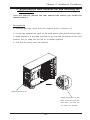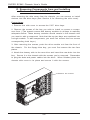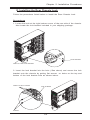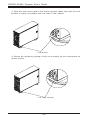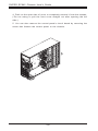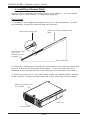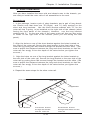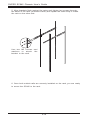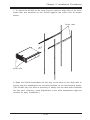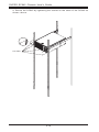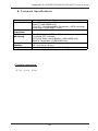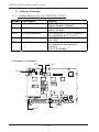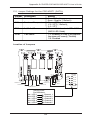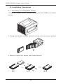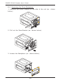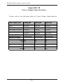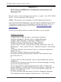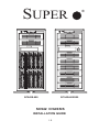
1
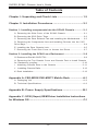
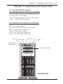
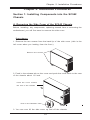
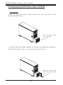
SUPER
SC942S-600
SC942i-600/550
SC942 CHASSIS
INSTALLATION GUIDE
1.0
®
SUPER SC942 Chassis User's Guide
Table of Contents
Chapter I: Unpacking and Check Lists .................................... 1-3
Chapter 2: Installation Procedures ........................................... 2-1
Section 1: Installing components into the SC942 Chassis ............. 2-1
A. Removing the Side Cover of the SC942 Chassis ................................ 2-1
B. Removing the SCSI Drive Trays .............................................................. 2-2
C. Removing the Rear Exhaust Fan and Installing the Motherboard ..... 2-3
D. Removing the Components from and Installing Devices into the 5.25"
Drive Bays ........................................................................................................ 2-4
E. Installing the Rear Chassis Lock ............................................................. 2-5
F. Removing the Front Side Cover to Access the Drives ....................... 2-7
Section 2: Installing the SC942 as a Rackmount ............................. 2-9
G. Rackmount Rail Kit-CSE-PT26 .................................................................. 2-9
H. Removing the Top Chassis Cover and Chassis Feet to install Chassis
for Rackmount purpose ................................................................................ 2-10
I. Attaching Chassis Ears to the Chassis ............................................... 2-11
J. Installing Chassis Rails .......................................................................... 2-12
K. Rack Installation ....................................................................................... 2-13
Appendix A: CSE-M35S/CSE-M35T1 Mobile Rack ................. A-1
A. Packaging List ........................................................................................... A - 2
B. Technical Specifications .......................................................................... A - 2
Appendix B: Power Supply Specifications ............................ B-1
Appendix C: SCSI (Super) GEM Driver Installation Instructions
for Windows OS ........................................................................... C-1
1-2
Chapter 1: Unpacking and Check Lists
Chapter 1- Unpacking and Check Lists
1-A. The SC942S-600 chassis
The SC942S chassis contains the following:
One (1) 5.25" drive bay (for floppy drive)
Two (2) 5.25" drive bays (for peripheral drives)
Ten (10) SCA 1" drive trays
Three (3) Hot-swappable 120mm chassis fans
One (1) 120mm rear exhaust fan
The accessory box contains the following:
One set of motherboard screws
One set of drive screws
One set of HDD (hard disk drive) screws
One (1) chassis lock mechanism
Three (3) AC power cords
One (1) 30" SCSI cable (CBL-028)
One (1) 10" SCSI cable (CBL-043)
PWR On HDD Activity OH PWR Fail LAN1
LAN2
Reset Button
Power Button
5.25" Expansion Bays
(SC942S-600)
1-3
SUPER SC942 Chassis User's Guide
1-B. The SC942i chassis
The SC942i chassis contains the following:
Eight (8) 5.25" peripheral drive bays
One (1) 5.25" drive bay for floppy drive
Three (3) Hot-swappable120mm chassis fans (*SC 942i-600)
Two (2) Hot-swappable120mm chassis fans (*SC 942i-550)
One (1) 120mm Rear Exhaust fan
Two (2) Front accessible USB 2.0 ports
The accessory box contains the following:
One set of motherboard screws
One set of drive screws
One set of HDD (hard disk drive) screws
One (1) chassis lock mechanism
One (1) AC power cord(*SC 942i-550)
Three (3) AC power cords(*SC 942i-600)
PWR On HDD Act OH PWR Fail LAN1 LAN2
Reset Button
Power Button
5.25" Expansion Bays
USB 2.0 Ports (*SC 942i only)
(SC942i-600/550)
1-4
Chapter 2: Installation Procedures
Chapter 2: Installation Procedures
Section 1: Installing Components into the SC942
Chassis
A. Removing the Side Cover of the SC942 Chassis
Before installing any components, replacing chassis fans or accessing the
motherboard, you will first need to remove the side cover.
Procedures
1. Remove the two screws from the back lip of the side cover (-this is the
left cover when you looking from the front.)
Remove the screws
2. Push in the release tab on the cover and push the cover back to the rear
of the chassis about 1/2 inch.
Push the cover toward
the rear of the chassis
Push in the Release Tab
3. You can now lift the side cover up and off the chassis.
2-1
SUPER SC942 Chassis User's Guide
B. Removing the SCSI Drive Trays (*SC942S)
Procedures
1.Pull out the SCSI Drive Trays located on the front side of the
chassis(*SC942S only)
Pull the SCSI Drive
Trays outwards
2. Pull the SCSI Drive Bay outwards, and press the release tab located on
the SCSI Drive Bay. Then, you can access the SCSI Drive.
Press the release tab
and open the drive bay
door
2-2
Chapter 2: Installation Procedures
C. Removing the Rear Exhaust Fan and Installing the
Motherboard
(You will need to remove the rear exhaust fan before you install the
motherboard.)
Procedures
1. Remove the side cover from the chassis (refer to Section A).
2. Locate the exhaust fan tabs on the back panel (See picture below right.)
3. Apply pressure to the tabs (located on the top and the bottom of the rear
exhaust fan) to snap the fan out of its locked position.
4. Pull the fan away from the chassis.
Rear Exhaust Fan
Apply Pressure to the
tabs to loosen the fan,
and then, pull the fan
out from the chassis.
2-3
SUPER SC942 Chassis User's Guide
D. Removing Components from and Installing
Devices into the 5.25" Drive Bays
After removing the side cover from the chassis, you can remove or install
devices into the drive bays (See Section A for removing the side cover).
Procedures
1. Remove the side cover to access the 5.25" drive bays.
2. Remove the screws of the bay you wish to install or remove a component from. (*The chassis comes with dummy modules in all bays to maintain
adequate airflow. These dummy modules should remain in the chassis until
you want to add a component. Note that the top two bays are combined into
a single module. To add components, you must first remove the four screws
corresponding both bays.)
3. After removing the screws, push the drive module out from the front of
the chassis. For the floppy drive bay, you must first remove the two face
plates.
4. Attach the dummy rails to the new drive and insert the new drive into the
bay. Secure it to the chassis with the screws you've removed. Remember
to plug the data and power cables into the drive. When finished, place the
chassis side cover to its place and secure it with the screws.
Remove the screws
2-4
Chapter 2: Installation Procedures
E. Installing the Rear Chassis Lock
Follow the procedures listed below to install the Rear Chassis Lock.
Procedures
1. Locate the hole at the right bottom corner of the rear side of the chassis.
Also locate the lock bracket included in your shipping package.
lock bracket
Hole for the lock bracket
2. Insert the lock bracket into the hole (*See above) and secure the lock
bracket onto the chassis by putting flat screws on holes on the top and
bottom of the lock bracket hole as shown below:
Holes for the screws
lock bracket
screws
2-5
SUPER SC942 Chassis User's Guide
3. Slide the side cover back to the proper position. Make sure that the lock
bracket is easily accessible from the rear of the chassis.
Lock Bracket
4. Secure the system by putting a lock(*not included) on the lock bracket as
shown below:
Lock (*Not included)
2-6
Chapter 2: Installation Procedures
F. Removing the Front Side Cover to Access the
Drives
(You do not need to remove the front bezel to access the drives. We
do not recommend removing the front cover unless you need to
access the control panel circuit board or the floppy drive.)
Procedures
1. Remove the side cover from the chassis (See Section A).
2. Push on the three tabs located inside the bottom side lip of the front
chassis cover.
3. Locate the 4 notches inside the side lip. Use a flat screw driver to loose
the notches and gently pry open the cover until the cover is out about 1/3
inches.
Notches
Push the tabs toward the lip and pry loose the notches to release
the cover. When freed about 1/3", push the cover to other side
of the chassis to completely release it.
2-7
SUPER SC942 Chassis User's Guide
4. Push on the open side of cover to completely remove it from the chassis.
(*Do not swing or pull the front cover straight out after opening the left
side.)
5. You can also remove the control panel's circuit board by removing the
screw that fastens the control panel to the chassis.
2-8
Chapter 2: Installation Procedures
Section 2: Installing the SC942 as a Rackmount
G. Rackmount Rail Kit: CSE-PT26
(* CSE-PT26 Sold separately.)
CSE-PT26 Rackmount kit (*For beige chassis), or
CSE-PT26 (B) Rackmount kit(*For black chassis)
Two (2) handle sets for rackmount chassis
Two (2) rack rail assemblies
Two (2) front brackets for mounting rack rails
Two (2) rear brackets for mounting rack rails
One (1) set of mounting screws
2-9
SUPER SC942 Chassis User's Guide
H. Removing the Top Chassis Cover and
Chassis Feet to Install as Rackmount
Procedures
1. Remove the side cover from the chassis (See Section A).
2. Press the release tab in the center of the cover lip while pushing the
cover toward the rear of the chassis at the same time. After the cover
stops, lift it off.
Press the Release Tab
3. Each chassis foot has a single screw. Remove the screw, then, depress
the foot's locking tab from inside of the chassis. Slide the foot off.
Push the cover
Chassis Feet
2-10
Chapter 2: Installation Procedures
I. Attaching Chassis Ears to the Chassis
After you have removed chassis feet from the chassis, you can now attach
chassis ears to the chassis.
Procedures
1. Remove the chassis feet from the chassis (See Section H).
2. Locate a pair of chassis ears and two sets of screws (3-each set)
included in the shipping package, and lay the chassis on a flat level as
shown below.
Screws
Chassis Ears
Screws
3. Align the chassis ears against the top and the bottom of the chassis as
shown above. Then, properly attach chassis ears to the chassis by tightening the screws provided as shown above.
SC942 Chassis with Chassis Ears attached
2-11
SUPER SC942 Chassis User's Guide
J. Installing Chassis Rails
After you have attached the chassis ears to the chassis, you can install
chassis rails to the chassis for rackmount purpose.
Procedures
1. Included in the shipping package are a pair of rail assemblies. In each
rail assembly, locate the inner rail and the outer rail.
Outer rail (*to be installed in the
rack)
Press the Locking Tab
Pull out the Inner
rail (*to be
attached on the
chassis)
Rail Assembly
2. Press the locking tab to release the inner rail from its locking position and
pull out the inner rail from the rail assembly. (*The inner rails are to be
attached to the chassis and the outer rails are to be installed in the rack.)
3. Attach the inner rail to one side of the chassis as shown below. Repeat
Steps 2 and 3 to attach another inner rail to the other side of the chassis.
Attach the Inner rail to
the chassis
Inner rail
Chassis ears
2-12
Chapter 2: Installation Procedures
K. Rack Installation
After you have installed the inner rails and chassis ears to the chassis, you
are ready to install the outer rails of rail assemblies to the rack.
Procedures
1. In the package, locate a pair of short brackets, and a pair of long brackets. Please note that there are "R"(-Right) and "L"(-Left) marked on the
short and long brackets. Use the short bracket marked with "R" for the
outer rail that is going to be installed on the right side of the chassis (when
facing the front panel of the chassis.) However, use the long bracket
marked with "L" on the rear side of the same outer rail that you are going
to install on the right side of the chassis (since you are facing the rear
panel).
2. Align the holes on one of the short bracket against the holes located on
the front of the outer rail. Secure the short bracket to the front side of the
outer rail by putting two M4 screws through the bracket and the slide. (*Be
sure to adjust the distance between the long and short brackets so that the
outer rail can snugly fit into the depth of the racks before you tighten the
screws.)
3. Align the holes on one of the long bracket against the holes located on
the rear side of the outer rail. Secure the long bracket to the rear side of the
outer rail by putting three M4 screws through the bracket and the slide. (*Be
sure to adjust the distance between the long and short brackets so that the
outer rail can snugly fit into the depth of the racks before you tighten the
screws.)
4. Repeat the same steps for the other outer rail.
Outer Rail
Rear side
Long Bracket
Front side
Short Bracket
Put two M4 Screws
through the bracket
and the outer rail
2-13
Put three M4 Screws
through the bracket and the
outer rail
SUPER SC942 Chassis User's Guide
5. Align brackets flush against the racks and tighten two screws through
the holes of the rack (as shown below) and repeat the same step to install
the rack on the other side.
Use two M5 screws and
washers to attach the
bracket to the rack.
6. Once both outside rails are securely installed on the rack, you are ready
to mount the SC942 to the rack.
2-14
Chapter 2: Installation Procedures
7. To mount the SC942 on the rack, first you need to align both of the inner
slides that are attached on the SC942 against the outer rails as shown
below:
Outer rails
Inner rails
8. Slide the SC942 Assemblies all the way to the back of the slide rails to
ensure that the assemblies are securely latched on the ball bearing slides.
(The SC942 may not slide in smoothly or easily into the rack when installed
the first time. However, some adjustment to the slide assemblies might be
needed for easy installation.)
2-15
SUPER SC942 Chassis User's Guide
9. Secure the SC942 by tightening the screws on the sides of the SC942 as
shown above.
screws
2-16
Appendix A
CSE-M35S/CSE-M35T1
Mobile Rack
User's Guide
Rev. 1.0
SUPER SC942 Chassis User's Guide
CSE-M35S/CSE-M35T1
Supermicro’s CSE-M35S/CSE-M35T1 Mobile Rack Series offers the cutting
edge technology with greater flexibility. The CSE-M35T1 supports five Serial ATA hot-swappable hard drives that yield a unparalleled storage capacity without compromising productivity by eliminating possible system
downtime.The CSE-M35S also accommodates five SCSI SCA 320/160 Hard
drives which provide configuration flexibility and maximum data integrity.
A. Packing List
Please check to see if you have received all the items listed below:
*CSE-M35S/CSE-M35T1 Mobile Rack
*90mm-Exhaust Fan (Fan-0057)
*Screws:
Flat Head Screws (13)
Round Head Screws (24)
Round Head Screws with Lock-Washer (7)
*Drive Carrier CSE-PT17/CSE-PT17(B)(-black) (5)
(*For CSE-M35T1 only)
*Serial ATA Backplane (CSE-SATAM35)
*(5)Serial ATA Cables (CBL-0044)
*Serial ATA LED cable (CBL-0057)
(*For CSE-M35S only)
*SCSI Backplane (CSE-SCAM942)
*SCSI cable (CBL-027-U320)
A-2
Appendix A: SUPER CSE-M35S/CSE-M35T1 User's Guide
B. Technical Specifications
Occupancy
Capacity
Cooling
Subsystem
System
Monitoring
Dimension
(WxHxD)
Weight
Three (3) 5.25" Drive Bays
Five (5) 1" SCA Ultra320/160 Hard Drives with SAF-TE
built-in (*CSE-M35S only)
Five (5) 1" Host Receptacle Connectors, SATA hot-swap
hard drives (*CSE-M35T-1 only)
One (1) 9cm Exhaust Fan
Fan Fail Detection LED and Alarm
Overheat LED indication
Drive Fail Alarm and Indication (*CSE-M35S only)
Built-in Termination (*CSE-M35S only)
146mm x 129mm x 245mm
(5.7 in x 5.0 in x 9.6 in)
Net: 5.9lb (2.9 kg), Gross: 7.5lb (3.7 kg)
Chassis supported:
SC762, SC830, SC942
A-3
SUPER SC942 Chassis User's Guide
C. Jumper Settings
C-1. Jumper Settings for the CSE-M35S (SCSI):
Jumper
JP18
Description
Buzzer Reset
JP21
SCSI Termination
JP24
SCSI ID Selection
JP29
GEM 318 IDs
JP30
Fan Sense
Setting
Closed: Enable,
Open: Disable (*Default)
Closed: Enable (*Default),
Open: Disable
1-2: SCSI Ids: 0,1,2,3,4 (*Default),
2-3: SCSI Ids: 9,10,11,12,13
1-2: ID6 (*Default),
2-3: ID8
Pins 1-2: Enable (*Default) (If a fan
is not present, the alarm will
sound.),
Pins 2-3: Disable
Location of Jumpers
JP30
JP21
Pin 1
Pin 1
Pin 1
Pin 1
JP29
Pin 1
JP18
JP24
A-4
Appendix A: SUPER CSE-M35S/CSE-M35T1 User's Guide
C-2. Jumper Settings for the CSE-M35T1 (SATA):
Jumper
Description
Setting
JP18
Buzzer Reset
JP25
Overheat Temperature
Closed: Enable,
Open: Disable (*Default)
Open: 45OC
1-2: 50OC (*Default),
2-3: 55OC
JP26
Act#1-Act#5
Connect this header to CBL-0057
(SATA LED Cable)
JP28:
Fan Sense
1-2: Enabled (if a fan is not present,
the alarm will sound) (*Default)
2-3: Disabled
Location of Jumpers
JP26
Pin 1
Pin 1
Channel #1
Channel #5
Channel #2
Channel #4
JP18
FAN
JP28
JP25
Key
COM
ACT8
ACT4
ACT7
ACT3
ACT6
ACT2
ACT5
ACT1
Channel #3
Activity LEDsPin Definitions
Channel 1
Act. LED 1
Channel 2
Act. LED 2
Channel 3
Act. LED 3
Channel 4
Act. LED 4
Channel 5
Act. LED 5
A-5
SUPER SC942 Chassis User's Guide
D. Installation Procedures
D-1. Accessing Hot Swappable Drives:
1.Push the release button located beside the drive LEDs (as shown
below:)
2. Swing the handle outward and pull out the unit (as shown below:)
3. Mount a drive in a carrier (as shown below:)
A-6
Appendix A: SUPER CSE-M35S/CSE-M35T1 User's Guide
D-2. Accessing the Exhaust Fan:
1.Push the tabs located on both sides of the unit (as
low:)
shown be-
2. Pull out the fan (as shown below:)
(*Note: For the SC-942 Chassis, the CSE-M35 Rear Exhaust Fan
should not be used. Instead, the hot-swappable 120mm Chassis
Fans included with the SC-942 Chassis should be connected to the
Backplane of the CSE-M35S/CSE-M35T1 Mobile Rack.)
A-7
SUPER SC942 Chassis User's Guide
D-3. Accessing the Drive Backplane:
1. Unscrew the screw located on the side of the unit (as
below:)
2. Pull out the Rear Bracket (as shown below:)
3. Access the Backplane (as shown below:)
A-8
shown
SUPER SC942 Chassis User's Guide
Appendix B
Power Supply Specifications
Please refer to the following table for Power Supply Specifications:
Power Supply Spec
SC942S-600
SC942i-600
SC942i-550
Model #
Part #
SP602-TS
PWS-044
SP602-TS
PWS-044
SP550-RP
PWS-046
Rated AC Input Voltage 100-240V AC
Rated Input Frequency 50-60 Hz
100-240V AC
50-60 Hz
100-240V AC
50-60 Hz
Rated Input Current
12A (115V)
6A (230V)
12A (115V)
6A (230V)
9A (115V)
4.5A (230V)
Rated Output Power
Maximum rated BTU
600W
3240 BTUs/Hr
600W
3240 BTUs/Hr
550W
2800 BTUs/Hr
Nominal DC Output
+3.3V 36A
36A
30A
+5V 30A
+12V 24A
30A
24A
30A
26A
-5V
-12V 1A
1A
0.8A
0.8A
+5Vsb 2A
2A
2.0A
B-1
Appendix B: Power Supply Specifications
Notes
B-2
SUPER SC942 Chassis User's Guide
Appendix C
SCSI (Super) GEM Driver Installation Instructions for
Windows OS
Please refer to the following instructions to install
Driver for the Windows OS systems.
the SCSI GEM
(*Note: This driver is not necessary for other Operating Systems.)
If you have two SCA backplanes, you will need to install the driver twice.
The driver is located on the Super Micro motherboard driver CD or is
available for download from our FTP site: ftp://ftp.supermicro.com/
driver/Qlogic/
Follow the procedure below to install this driver to your system.
Installing the driver:
1) Right click on “My Computer” and choose “Property”.
2) Select “Hardware” tab and click on “Device Manager”.
3) Open “Other Devices” or wherever “GEM318” is on.
4) Right click on this device and choose “Property”.
5) Click on “Driver” tab and choose “Update Driver”.
6) Click “Next” 2 times, uncheck both “Floppy disk drives” and “CDROM drives”. Then, select the item- “Specify a location,” and choose
“Next”.
7) Click on “Browse” and choose D drive or wherever Supermicro
Setup CD is in.
8) Choose “Qlogic” folder and click on “Open”.
9) System will automatically detect GEM318 and install the drive
from this point on.
or,
1) Right click the "My Computer" icon on your desktop and choose
Properties.
2) Click on the Hardware tab and click on "Device Manager" to bring
up the list of system devices.
3) You may see one or two yellow question marks (?) that read
QLogic GEM354 or GEM318 SCSI Processor Device. Right click on
these, and choose to uninstall. If two such question marks are
present, uninstall both.
4) Click on Action tab and choose "Scan for Hardware Changes".
The Hardware Wizard program should start up. Click "Next".
C-1
Appendix C: Installation Instuctions for the SCSI GEM Driver
5) At the first prompt, choose “Display a list of known device drivers
for the device so that I can choose a specific driver” and click "Next".
6) Choose “Other Devices” and click Next.
7) Choose “Have Disk”, and specify your floppy drive location in the
options box. Then, click "Next".
8) Highlight “Enclosure Services Device” and click "Next".
9) Ignore the warning prompt by clicking "Yes".
C-2