1
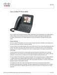
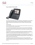
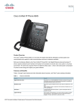
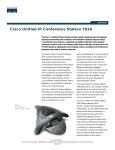
Data Sheet
Cisco Unified IP Phone Power Injector
®
The Cisco Unified IP Phone Power Injector (Figure 1) increases the deployment flexibility of Cisco Unified IP phones
by providing an alternative powering option to local power, multiport power patch panels, and inline-power-capable switches.
Figure 1.
Cisco Unified IP Phone Power Injector (Front, Back, and Stacked Views)
The Cisco Unified IP Phone Power Injector is a midspan power injector designed and tested for use with Cisco Unified IP phones. The
Cisco Unified IP Phone Power Injector sits between a switch port and the Cisco Unified IP phone, providing inline power capability to an
unpowered switch port. It supports Cisco midspan power, IEEE 802.3af modes for supplying power to the attached phone, and
10/100/1000BASE-T Ethernet connections. Figure 2 shows the maximum distance of the Cisco Unified IP Phone Power Injector between a
Cisco Unified IP phone and an Ethernet switch.
Figure 2.
Network Diagram
All contents are Copyright © 1992–2006 Cisco Systems, Inc. All rights reserved. This document is Cisco Public Information.
Page 1 of 5
FEATURES
The Cisco Unified IP Phone Power Injector offers several features, including:
●
A desktop and desk-area single-port midspan injector with integrated power
●
802.3af/IEEE Power over Ethernet (PoE) support
●
Gigabit Ethernet support
●
Full enterprise-level compliance
●
Designed and tested for use with Cisco Unified IP Phones
SPECIFICATIONS
Table 1 lists specifications of the Cisco Unified IP Phone Power Injector.
Table 1.
Specifications of the Cisco Unified IP Phone Power Injector
Specification
Description
Dimensions (H x W x D)
1.6 x 4.6 x 5.45 in. (4.1 x 11.8 x 13.8 cm)
Weight
.66 lb (.30 kg)
Phone casing composition
Polycarbonate acrylonitrile butadiene styerene (ABS) plastic in textured dark gray color
Power requirements
Power is integrated (see Table 5 for country-specific power cords used for connection to AC wall outlet)
Part number
CP-PWR-INJ
LAN connection
● Maximum Ethernet cable length: 100 m from switch to device
● Type: RJ-45
● Label: DATA—Network
Device connection
● Maximum Ethernet cable length: 100 m from switch to device
● Type: RJ-45
● Label: DATA and PWR—PHONE
LEDs
Two—”Power” and “Status”
Stackable
Yes—Two injectors can be stacked
Wired pairs used
Injects power into two unused pairs in the Ethernet cable: 4 and 5 (negative) and 7 and 8 (positive)
Electrical
Input:
● AC input voltage range: 90 to 264 VAC
● AC input current: 0.5A (RMS) @ 90 VAC at maximum load
● AC input frequency: 47 to 63 Hz
● Maximum inrush current: 20A @ 115 VAC, 60 Hz, Cold Start, 25°C
40A @ 230 VAC, 50 Hz, Cold Start, 25°C
Output:
● DC output voltage: 48 VDC nominal
● Maximum output power: 15.5W @ 48 VDC
Performance efficiency:
● 53% minimum at 30–49% of maximum load and 120 VAC, 60 Hz
● 75% minimum at 50–100% of maximum load and 120 VAC, 60 Hz
All contents are Copyright © 1992–2006 Cisco Systems, Inc. All rights reserved. This document is Cisco Public Information.
Page 2 of 5
TEMPERATURE
Table 2 gives temperature ratings for the Cisco Unified IP Phone Power Injector.
Table 2.
Temperature Ratings for Cisco Unified IP Phone Power Injector
Temperature Variable
Description
Operating temperature
32 to 104°F (0 to 40°C)
Relative humidity
10 to 95% (noncondensing)
Storage temperature
14 to 140°F (–10 to 60°C)
CERTIFICATIONS
Table 3 gives certifications for the Cisco Unified IP Phone Power Injector.
Table 3.
Certifications for Cisco Unified IP Phone Power Injector
Certification
Description
Regulatory compliance
● CE marking
Safety
● Underwriters Laboratories (UL) 60950
● Canadian Standards Association (CSA) C22.2 No. 60950
● IEC 60950
● EN 60950
● AS/NZS 60950
Electromagnetic compatibility (EMC)
● Federal Communications Commission (FCC) Part 15 (CFR 47) Class B
● ICES-003 Class B
● EN55022 Class B
● CISPR22 Class B
● AS/NZ 3548 Class B
● VCCI Class B
● EN55024
● EN 50082-1
● EN 61000-3-2
● EN 61000-3-3
● CISPR24
● EN61000-6-1
ORDERING INFORMATION
Table 4 gives ordering information for the Cisco Unified IP Phone Power Injector.
Table 4.
Ordering Information for Cisco Unified IP Phone Power Injector
Part Number
Description
CP-PWR-INJ
Cisco Unified IP Phone Power Injector
CP-PWR-INJ=
Cisco Unified IP Phone Power Injector, spare
All contents are Copyright © 1992–2006 Cisco Systems, Inc. All rights reserved. This document is Cisco Public Information.
Page 3 of 5
POWER CORDS
Table 5 lists the AC country power cords needed for the Cisco Unified IP Phone Power Injector. An AC power cord is required to power
the unit.
Table 5.
AC Country Power Cords
Part Number
Description
CP-PWR-CORD-AP=
Asia Pacific
CP-PWR-CORD-AR=
Argentina
CP-PWR-CORD-AU=
Australia
CP-PWR-CORD-CE=
European Community
CP-PWR-CORD-CN=
China
CP-PWR-CORD-JP=
Japan
CP-PWR-CORD-NA=
North America
CP-PWR-CORD-SW=
Switzerland
CP-PWR-CORD-UK=
United Kingdom
WARRANTY
®
The Cisco Unified IP Phone Power Injector is covered by a Cisco Systems standard one-year replacement warranty.
CISCO UNIFIED IP COMMUNICATIONS SERVICES AND SUPPORT
Cisco Unified IP Communications services and support reduce the cost, time, and complexity associated with implementing a converged
network. Cisco and its partners have designed and deployed some of today’s largest and most complex IP Communications networks—they
understand how to integrate an IP Communications solution into your network.
Cisco design tools and best practices help ensure the solution best fits your business needs from the start, eliminating costly redesigns and
downtime. Proven methods help ensure a sound implementation that will deliver the functions and features you expect—on time. Support
services include remote network operations, network management tools to administer the converged application and network infrastructure,
and technical support services.
Through these services, your organization benefits from the experience gained by Cisco and its partners. Taking advantage of this valuable
experience, you can create and maintain a resilient, converged network that will meet your business needs today—and in the future.
All contents are Copyright © 1992–2006 Cisco Systems, Inc. All rights reserved. This document is Cisco Public Information.
Page 4 of 5
Printed in USA
All contents are Copyright © 1992–2006 Cisco Systems, Inc. All rights reserved. This document is Cisco Public Information.
C78-352107-00 06/06
Page 5 of 5