1
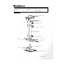
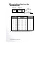
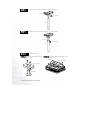
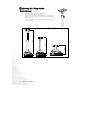
MP610 / MP720 / MP770
Ceiling Mounting Guide
Welcome
Copyright
Copyright 2005 by BenQ Corporation. All rights reserved. No part of this publication may be reproduced, transmitted, transcribed,
stored in a retrieval system or translated into any language or computer language, in any form or by any means, electronic,
mechanical, magnetic, optical, chemical, manual or otherwise, without the prior written permission of this company.
Disclaimer
BenQ Corporation makes no representations or warranties, either expressed or implied, with respect to the contents hereof and
specifically disclaims any warranties, merchantability or fitness for any particular purpose. Further, BenQ Corporation reserves the
right to revise this publication and to make changes from time to time in the contents hereof without obligation of this company
to notify any person of such revision or changes.
Safety Instructions
1.
2.
3.
4.
5.
6.
7.
8.
9.
10.
11.
12.
Follow the instructions in this guide when installing the projector with this bracket. Improper or inadequate installation
could cause the projector to fall and cause injures.
Make sure the installation is secure enough to bear the weight of all and withstand vibrations.
Use only the parts provided with the bracket, and any parts (commercially available) that are specified in this guide.
Do not modify the bracket or the parts provided with the bracket.
Do not use damaged parts. If any parts become damaged, contact your dealer.
All bolts and screws must be tightened securely.
Make sure not to block any ventilation openings when installing the projector.
Do not install the projector in a location that is subject to high levels of dust or humidity.
Do not install the projector in a location that is exposed to direct sunlight or in a location that is subject to extreme
fluctuations in temperature (such as near an air conditioner).
Clean only with a dry cloth.
Special techniques and experience are required when installing the projector with this bracket. It is recommended that you
contact your dealer to install the projector for you.
Once the projector is installed, safety checks should be conducted on a regular basis.
Table of Contents
Packing Parts List ................................................................................................................................................................................. 3
Projector Installation and Throw Distance Chart .............................................................................................................................. 4
Installing a Projector with The Ceiling Bracket.................................................................................................................................. 5
Adjusting the Ceiling Bracket .............................................................................................................................................................. 8
Specifications and Diagrams ............................................................................................................................................................. 10
2 Copyright
Packing Parts List
CEILING ADAPTER
PIPE
PROJECTOR ADAPTER
WASHER x 1
U-PLATE
PIPE-BASE
V – ADJUST BOLT
M4 SCREW x 10
TUBE
H – ADJUST ADAPTER
NUT x 7
BOLT x 6 (TUBE BOLT x 2, L – ADJUST
BOLT x 2, PIPE BOLT x 2)
Names of Parts
U - PLATE
CEILING ADAPTER
M4 SCREW x 2
TUBE
Nut
TUBE BOLT x 2
L-ADJUST BOLT x 2
PIPE
PIPE BOLT x 2
M4 SCREW x 4
H - ADJUST ADAPTER
V – ADJUST BOLT
PIPE BASE
M4 SCREW x 3
PROJECTOR ADAPTER
Packing Parts List 3
Projector Installation and Throw Distance Chart
Floor Installation for a 4:3 screen
Maximum zoom
Minimum zoom
Screen
Center of lens
Vertical Offset
Projection distance
Feet
Inches
mm
4
48
5
6
60
72
7
8
84
96
9
108
10
120
12
144
15
180
18
216
25
300
1219
1500
1524
1829
2000
2134
2438
2500
2743
3000
3048
3500
3658
4000
4572
5000
5436
6000
7620
Distance from Screen in mm
Min length
Average
Max length
(with max.
(with min.
zoom)
zoom)
1745
2148
2182
2618
2863
3055
3491
3579
3927
4295
4364
5011
5236
5727
6545
7158
7855
8590
10909
1876
2199
2345
2815
3078
3284
3753
3848
4222
4617
4691
5387
5629
6157
7036
7695
8444
9234
11727
2007
2250
2509
3011
3293
3513
4015
4116
4516
4939
5018
5763
6022
6586
7527
8232
9033
9878
12545
Vertical Offset in mm
18
23
23
27
30
32
36
38
41
45
46
53
55
60
69
75
82
90
114
The recommended focus range is from 1500-8000 millimeters (1.5-8 meters).
There is 3%-5% tolerance among these numbers due to optical component variations.
4 Projector Installation and Throw Distance Chart
Installing a Projector with The Ceiling Bracket
Overview
Q
Diagram of completed installation
Q
Ceiling Mount Device
Installation Procedure
Insert the U-PLATE into the CEILING ADAPTER, and tighten two M4 screws (from the bottom) into the
STEP A
screw holes. Then attach the top part to the ceiling.
U-PLATE
CEILING ADAPTER
M4 screws
Ceiling mount screws
(not included)
Installing a Projector with the Ceiling Bracket
5
STEP B
Install the TUBE and the U-PLATE with 2 sets of bolts & nuts (TUBE BOLT).
NUTS x 2
TUBE BOLTS x 2
TUBE
STEP C
Install the PIPE and the TUBE with 2 sets of bolts & nuts (L-ADJUST BOLT).
NUTS x 2
L-ADJUST BOLTS x2
PIPE
STEP D
Install the base-assembly.
STEP D1 Attach the PIPE-BASE to the H-ADJUST
ADAPTER with 2 M4 screws.
M4 screw
STEP D2 Assemble the PROJECTOR ADAPTER and the
projector with 3 M4 screws.
M4 screw
PROJECTOR ADAPTER
H-ADJUST ADAPTER
PIPE-BASE
6 Installing a Projector with the Ceiling Bracket
STEP E
Combine the H-ADJUST ADAPTER (including the PIPE-BASE) and the PROJECTOR ADAPTER with
one V-ADJUST BOLT set (bolt, washer and nut). Then tighten the M4 screws on both sides.
NUT
WASHER
H-ADJUST ADAPTER
M4 screw
V-ADJUST BOLT
Assemble BASE-ASSEMBLY and the ceiling mount device with 2 sets of bolts and nuts (PIPE BOLT
sets).
*Two people are required for the completion of this step.
STEP F
Ceiling mount bracket
NUT
BASE-ASSEMBLY
PIPE BOLT
Installation finished.
Installing a Projector with the Ceiling Bracket
7
Adjusting the Ceiling Bracket
Height Adjustment
1.
2.
3.
4.
5.
Make sure to remove the projector first.
Loosen the nuts securing to the two L-ADJUST BOLTS.
Remove the L-ADJUST BOLTS from the PIPE.
Adjust to the correct position for the height of the screen. The height can be
adjusted to 218mm or any value in a range between 548mm and 758mm in
increments of 30 mm.
Insert the L-ADJUST BOLT back into the PIPE, and then re-attach the nuts
previously removed.
Minimum Height
218
Maximum Height
8
Adjusting the Ceiling Bracket
Horizontal Angle Adjustment
1.
2.
3.
4.
Loosen the two sets of screws connecting the PIPE-BASE and the
H-ADJUST ADAPTER.
Adjust the horizontal angle so that it is correct for the orientation of the
screen.
Re-tighten the two sets of screws connecting the PIPE-BASE and the
H-ADJUST ADAPTER.
The swivel angle can be set within a range of negative to positive 30
degrees.
Vertical Angle Adjustment
1.
2.
3.
4.
Loosen the two sets of screws connecting the H-ADJUST ADAPTER
and the PROJECTOR ADAPTER.
Adjust the vertical angle to the correct one for the orientation of the
screen.
Re-tighten the 2 sets of screws connecting the H-ADJUST ADAPTER
and the PROJECTOR ADAPTER.
The tilt angle can be adjusted in a range between +5 and -15 degrees.
5
Adjusting the Ceiling Bracket 9
Specifications and Diagrams
Specifications
Adjustment Range
Height
Horizontal angle
Vertical angle
218mm, 548mm, 578mm, 608mm, 638mm, 668mm, 698mm, 728mm and 758mm.
–30 to +30 degrees
+5 to -15 degrees
Weight
3.2 kg
Loading
3.5 kg
Diagrams
Q
Left View
10 Specifications and Diagrams
Q
Front view
Q
Right view