1
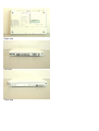
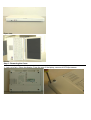
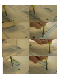
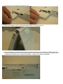
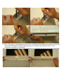
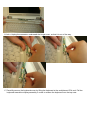
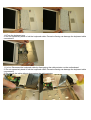
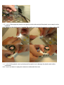
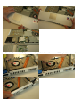
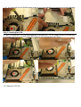
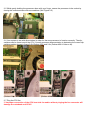
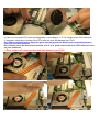
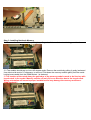
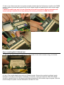
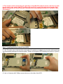
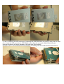
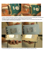
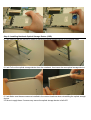
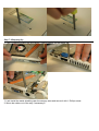
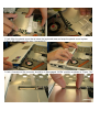
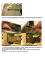
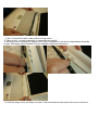
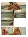
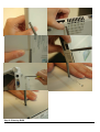
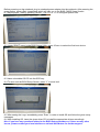
COMPATIBLE
Installation Guide
Copyright © 2005 MSI Computer Corp.
Overview:
MS-1012 is shipped out as a bare bone. Some of the components are equipped while some are not. This
installation guide provides you with the information of notebook hardware setup. Before assembling your
notebook, please prepare installation tools and appropriate items. If you are not sure about the items,
please contact your dealer for more information.
Package check list:
Optional Hardware Devices:
HDD, Mini PCI WLAN card, CPU, Memory
Before installing the notebook
•
•
•
The peripheral devices contained herein depend on your actual system configuration.
Third-party trademarks and names are the properties of their respective owners.
The information contained herein relevant to software and hardware are for reference only and in
accordance with actual system configuration. All information are subject to change without notice.
Warning!
•
Ensure power is turned off and notebook battery is removed before you install any hardware
devices.
•
Use a grounded wrist strap before handling computer components such as CPU, Memory, HDD,
mini-PCI Card, etc.
•
Place components (CPU, Memory, HDD, mini-PCI Card, etc) on a grounded antistatic pad or on a
bed that comes with the components whenever the components are separated from the
notebook.
•
If you have any difficulties in installing hardware devices, please contact your dealer for further
information.
Open View
1. Cover latch
2. Display Panel
3. Quick Launch Buttons and Power button
4. Status LEDs
5. Keyboard
6. Touchpad
7. Stereo Speakers
Bottom View
1. Battery Unlock Button
2. Battery Pack
Right view
Left view
Front view
Open view
Others:
Step 1: Removing the Cover
1-1 a.b.c.d.e.f.g.h.i Close the display. From the rear of the laptop, remove all 9 Philips screws.
1-2 a.b Remove both PCMCIA card and SD card.
1-3 Open your laptop to a 30 to 45 degree angle shown in the Figure below.
1-4 a.b.c.d.e Prepare a proper size flat head screwdriver and locate the 3 notches. Carefully insert the
flathead screwdriver into the notches and gently lift up the hinge cover. Gently pry the hinge covers if
needed and be careful not to damage the plastics, wireless, and cables underneath.
1-5 a.b.c If necessary, while holding the hinge cover, carefully insert the flathead screwdriver under both
side below the display assembly hinge, gently pry up, and then lift the hinge cover out. This
procedure may need to be repeated.
Hint: Gently pry the hinge cover if needed. Be careful not to damage the plastics and cables underneath.
1-6 a.b.c Unplug the connector underneath the hinge cover, so that it is out of the way.
1-7 Carefully remove the keyboard cover by lifting the keyboard at the switchboard PCA end. Pull the
keyboard toward the display assembly in order to release the keyboard from the top case.
1-8 Turn the keyboard over
!!! Do not excessively bend or fold the keyboard cable. Excessive flexing can damage the keyboard cable
connectors!!!
1-9 a.b.c Disconnect the keyboard cable by disengaging the cable actuator on the motherboard.
!!! Do not excessively bend or fold the keyboard cable. Excessive flexing can damage the keyboard cable
connectors!!!
!!! Do not pull the cable without disengaging the cable actuator.
1-10 a.b.c.d Disengage the plastic cover gently at both sides and pull the plastic cover away from the
notebook.
Hint: Gently pry the plastic cover if needed. Be careful not to damage the plastics or cables underneath.
1-11 a.b.c Lift the plastic cover up slowly and be careful not to damage the plastics and cables
underneath.
Hint: You do not have to unplug the connector underneath the cover.
1-12 a.b.c Remove the 2 Philips screws on the plastic tab from the case and lift the plastic tab upward.
1-13 a.b Unscrew only the Phillips-head screw on the metal shielding and remove the metal shielding.
Step 2: Installing the CPU
2-1 a.b.c.d Unlock the CPU heat sink diagonally or according to “1-2-3-4” shown on the CPU heat sink.
!!! Improper unlocking or locking of the CPU heat sink nuts will damage the CPU!!!
2-2 Unplug the CPU fan.
2-3 Use a flathead screwdriver to disengage (Open) the socket actuator, as shown in figure 2-3a below.
The socket actuator should open after only a half turn, and then you should be able to remove the
processor with your fingers.
Hint: Make sure your system can accommodate the Intel Pentium M /Celeron M Processor that you want
to install. Check for motherboard, BIOS, and thermal compatibility by using the given documentation, or
by contacting the vendor if necessary. This processor should only be installed in systems supporting the
Intel Pentium M Processor.
2-4 Place new processor into the socket. Align processor’s pin A1 (shown in figure 2-4) with the arrow on
the micro-FCPGA socket. Pin A1 of the processor is identified with an embroidered corner and pin A1 of
the socket is identified with a small arrow. If the processor does not drop completely into the socket, turn
the actuator until the processor drops in completely.
!!!You do not have to press down the processor. If the processor does not drop completely into the
socket, turn the actuator until the processor drops in completely.
2-5 While gently holding the processor down with your finger, secure the processor in the socket by
closing the socket actuator with a screwdriver (See Figure 2-5)
2-6 Your system is set with dip-switches in order for the new processor to function correctly. The dipswitches can be found next to the CPU. Consult processor documentation to determine the correct dipswitches setting shown in figure 2-6b (Dothan 533) and 2-6c (Dothan 400 & Celeron M).
(Dothan 533)
(Dothan 400 & Celeron M)
2-7 Plug the CPU fan.
!!! Improper connection of the CPU heat sink fan and/or without pluging the fan connector will
damage the notebook and CPU!!!
2-8 a.b.c.d.e Lock the CPU heat sink diagonally or according to “1-2-3-4” shown on the CPU heat sink.
!!! Improper unlocking or locking of the CPU heat sink nuts will damage the CPU!!!
Hint: We recommend you to apply the given thermal grease for better heat conduction between
your CPU and the heat sink.
Hint: Please check the heat sink and make sure it is in good contact with the CPU before you turn
on your notebook.
!!! Poor contact will cause overheat and may damage your CPU!!!
Step 3: Installing Notebook Memory
3-1 Remove the older module (if replacing) by pulling tabs of the socket outward using your thumbs.
3-2 The module should pop up into a 45 degree angle. Remove the module by pulling it gently backward.
Use side-to-side motion, if necessary, to remove. Push down the memory module gently until the metallocking levers aside from the DIMM socket 1 is fastened.
!!! The location of the notch along the gold edge of the memory module needs to be lined up with
keyed notch in the socket. Memory module can only fit in one direction due to the keyed notch.
Wrong orientation will cause improper installation and may damage the memory modules or
DIMM sockets!!!
3-3 a.b.c If you have more than one memory module, please align the 2nd memory module to the DIMM
socket 2. Memory should be inserted firmly at a 45 degree angle and pushed down until module snaps
into place.
!!! Memory module can only fit in one direction due to the keyed notch. Wrong orientation will
cause improper installation and may damage the memory modules or DIMM sockets!!!
Step 4: Installing Mini PCI WLAN Card
4-1 Remove the older module (if replacing) by pulling tabs of the socket outward using your thumbs.
4-2 a.b.c The module should pop up into a 45 degree angle. Remove the module by pulling it gently
backward. Use side-to-side motion, if necessary, to remove. Unplug the antennas. Mini PCI module
should be inserted firmly at a 45 degree angle and pushed down until module snaps into place. After the
module snaps into place, connect antennas on the Mini PCI card.
!!! The location of the notch along the gold edge of the Mini PCI module needs to be lined up with
keyed notch in the socket. Mini PCI module can only fit in one direction due to the keyed notch.
Wrong orientation will cause improper installation and may damage the Mini PCI module or Mini
PCI socket!!!
Step 5: Installing Notebook Hard Drive (HDD)
5-1 a.b Tilt up the rear of the hard drive case and pull it gently by its edges only, because static electricity
can permanently damage the computer parts. Please use the given HDD shielding tray (refer to Figure 51a)
5-2 a.b.c.d Unscrew all 4 Phillips screws that are on the side of the HDD.
5-3 a.b.c.d Remove the HDD connector (if replacing the older hard drive) by pulling it away from the hard
drive. Insert the HDD connector to HDD. Make sure to align the connector and the hard drive pin.
Improper alignment will cause damage to the hard drive and notebook.
!!!There is only 1 correct alignment and orientation in installing hard drive and hard drive connector!!!
5-4 a.b.c.d Slide the hard drive (with the connector) into the given hard drive shielding bay and fasten the
hard drive you want to install with the 4 attached Phillips screws on the side.
!!! Failure to apply 4 screws may cause hard drive assembly to fall off in the notebook hard drive area
and will damage the hard drive and notebook!!!
5-5 a.b Carefully place the entire hard drive assembly into the notebook hard drive area.
Step 6: Installing Notebook Optical Storage Device (OSD)
6-1 a.b Remove the two screws in order to secure the optical storage device on the bottom case.
6-2 a.b Pull out the optical storage device from the notebook, then insert the new optical storage device.
6-3 a.b Make sure these screws are installed in the correct locations when reinstalling the optical storage
device.
!!!Failure to apply these 2 screws may cause the optical storage device to fall off!!!
Step 7: Wrapping Up
7-1 a.b.c Install the plastic tab and fasten 2 Phillips screws on the plastic tab.
7-2 a.b Install the metal shielding near the memory area and secure it with 1 Phillips screw.
!!! Move the cables out of the way if necessary!!!
7-3 a.b Align the plastic cover that is below the keyboard area and snap the plastic cover in place.
!!! Move the cables out of the way if necessary!!!
7-4 a.b.c Actuator on the connector should be in disengaged “OPEN” position as shown in “Figure 7-4c”
7-5 a.b.c.d Lay the keyboard face down on top of the case. Connect the keyboard cable and engage the
cable and connector in place by pressing down the actuator.
!!!Do not excessively bend or fold the keyboard cable. Excessive flexing can damage the keyboard
connector!!!
Correct Keyboard Cable connection
Incorrect Keyboard Cable connection
7-6 Then put the keyboard in its normal position. Slide the metal tabs on the bottom of the keyboard into
their slots in the top case and lower the keyboard into place.
!!!Do not excessively bend or fold the keyboard cable. Excessive flexing can damage the keyboard
connector!!!
!!!There is only 1 correct connection of connecting keyboard cable!!!
7-7 a.b.c Connect the cable underneath the hinge cover.
!!! There is only 1 correct connection of connecting the cable!!!
!!! Be careful not to damage the antenna PCA that is connected to the left and right display assembly
hinges. Damaging either antenna PCA can degrade notebook performance.
7-8 Hold the hinge cover and snap it in place. Push downward at each end of the cover to secure it.
7-9 Fasten all 9 Phillips-head screws.
!!! Failure to apply any screws will damage the notebook.
Step 8: Entering BIOS
Before powering on the notebook, plug in notebook power adapter into the notebook. After pressing the
power button, press <Del> immediately which will take you to the BIOS CMOS Setup Screen.
8-1 Adjust proper TIME by pressing <Enter>. Use <+> or <-> to configure system time.
8-2 Under “BOOT” menu in the BIOS Setup Utility, press <Enter> to select the first boot device.
8-3 Insert a bootable OS CD into the OSD tray.
8-4 To save/ exit the BIOS Setup Screen, press “Y” to save/ exit.
8-5 After seeing the Logo, immediately press “Enter” in order to install OS and follow the given setup
messages.
8-6 After installing OS, insert the given driver CD to install the appropriate drivers accordingly.
Hint: If you have any questions related to the BIOS Setup procedure or if there are any other
issues, please contact your local retailers or national distributors for further support.