1
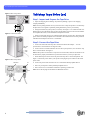
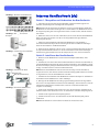
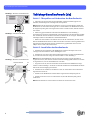
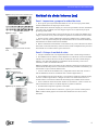
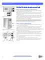
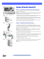
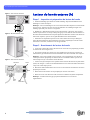
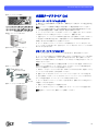
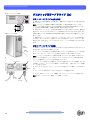
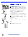
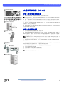
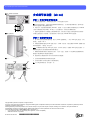
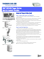
DLT VS160 Tape Drive
Quick Install Guide
Internal Tape Drive (en)
Figure 1: Back of Tape Drive
Step 1: Inspect and Prepare the Tape Drive
a. Inspect the shipping box for damage. If you find any damage, report it to the shipping
company immediately.
SCSI ID jumpers
Note: Save the packing materials in case you need to move or ship the tape drive. You must ship
the tape drive in the original or equivalent packing materials to preserve your warranty.
Factory default SCSI ID
b. Select a server or workstation to host your tape drive. Shut down and power off the host and
all peripheral devices attached to the selected host.
Figure 2: Install in Drive Bay
c. Change the SCSI ID for your tape drive, if necessary. See Figure 1. Use the SCSI jumpers to
set the SCSI ID. For complete instructions, see the Installation and Operations Guide.
d. Remove the cover from the server or workstation as described in the server or workstation’s
manual. If necessary, install an LVD/SE host bus adapter in the server or workstation.
Step 2: Install the Tape Drive
Figure 3: Terminate SCSI Cable
a. Install your tape drive in a half-height drive bay. See Figure 2.
b. Connect an active LVD/SE terminator onto one end of your SCSI cable, if your tape drive is
the last or only device on the SCSI bus. See Figure 3. If the SCSI cable that came with your SCSI
host bus adapter already has a terminator built into it, do not use an additional terminator.
Note: If the tape drive is not the last or only device on the SCSI bus, make sure the last device on
the SCSI bus is properly terminated and is powered on whenever you use your tape drive.
c. Connect the SCSI cable to the tape drive and to the SCSI host bus adapter. Connect the power
cable to your tape drive. See Figure 4.
Figure 4: Connect the Cables
d. Secure the tape drive in the selected server or workstation with the appropriate mounting
screws. See Figure 5. Contact your computer manufacturer if the server or workstation uses
mounting rails for internal tape drives.
SCSI cable
(with terminator)
e. Re-install the cover on the server or workstation. Re-connect the power cables to any attached
peripheral devices.
f. Power on any attached peripheral devices.
Power
cable
Figure 5: Secure the Tape Drive
g. Power on the server or workstation and allow its operating system to start.
Note: Turn to the last page for information on additional resources.
DLT VS160 Tape Drive Quick Install Guide
Tabletop Tape Drive (en)
Figure 1: Back of Tape Drive
Step 1: Inspect and Prepare the Tape Drive
a. Inspect the shipping box for damage. If you find any damage, report it to the shipping
company immediately.
Note: Save the packing materials in case you need to move or ship the tape drive. You must ship
the tape drive in the original or equivalent packing materials to preserve your warranty.
b. Change the SCSI ID for your tape drive, if necessary. See Figure 1. Use a small screwdriver or
ballpoint pen to press the buttons above or below the SCSI ID to increase or decrease the number.
For complete instructions, see the Installation and Operations Guide.
Figure 2: Connect the Cables
c. Select a location near the server or workstation that will host your tape drive. Shut down and
power off the host and all peripheral devices attached to the selected host. If necessary, install an
LVD/SE host bus adapter in the server or workstation.
Step 2: Connect the Tape Drive
a. Connect the SCSI cable to the tape drive and to the SCSI host bus adapter — or to the
previous device on the SCSI bus. See Figures 2 and 3.
SCSI host
adapter
b. Connect an active LVD/SE terminator onto one end of your tape drive, if it is the last or only
device on the SCSI bus. See Figure 3.
SCSI
cable
Note: If the tape drive is not the last or only device on the SCSI bus, make sure the last device on
the SCSI bus is properly terminated and is powered on whenever you use your tape drive.
c. Ensure that the power switch on the rear panel of the tape drive is in the OFF position. See
Figure 3. Connect the power cable to your tape drive and plug the power cable in to the nearest
power outlet.
Figure 3: Back of Tape Drive
Terminator
On
d. Connect the power cables to the host server or workstation and all peripheral devices.
e. Power on your tape drive and any attached peripheral devices.
f. Power on the server or workstation and allow its operating system to start.
Off
SCSI
cable
2
Power
cable
Note: Turn to the last page for information on additional resources.
DLT VS160 Tape Drive Quick Install Guide
Abbildung 1: Rückseite des Bandlaufwerks
Internes Bandlaufwerk (de)
Schritt 1: Überprüfen und Vorbereiten des Bandlaufwerks
a. Überprüfen Sie die Verpackung auf Versandschäden. Sollten Sie Schäden jeglicher Art
feststellen, benachrichtigen Sie unverzüglich die Transportfirma.
SCSI-ID-Jumper
Werkseitig voreingestellte SCSI-ID
Abbildung 2: Montage im LaufwerkSteckplatz
Hinweis: Heben Sie die Verpackung auf, damit Sie sie erneut verwenden können, falls Sie das
Bandlaufwerk an einen anderen Ort bringen oder versenden müssen. Das Bandlaufwerk muss in
der Originalverpackung oder einem angemessenen Ersatz versendet werden, damit die Garantie
nicht erlischt.
b. Wählen Sie einen Server oder eine Arbeitsstation, der bzw. die als Host für das Bandlaufwerk
dienen soll. Fahren Sie den Host sowie alle an den ausgewählten Host angeschlossenen
Peripheriegeräte herunter.
c. Ändern Sie gegebenenfalls die SCSI-ID für das Bandlaufwerk. Siehe Abbildung 1.
Verwenden Sie die SCSI-Jumper für die Einrichtung der SCSI-ID. Ausführliche Anleitungen
finden Sie im Installations- und Benutzerhandbuch.
Abbildung 3: Terminierung des SCSI-Kabels
d. Entfernen Sie die Abdeckung vom Server bzw. von der Arbeitsstation. Befolgen Sie dabei die
im entsprechenden Handbuch des Servers oder der Arbeitsstation beschriebenen Anleitungen.
Installieren Sie gegebenenfalls einen LVD-/SE-Adapter im Server bzw. in der Arbeitsstation.
Schritt 2: Installieren des Bandlaufwerks
a. Montieren Sie das Bandlaufwerk in einem Laufwerk-Steckplatz (halbe Höhe). Siehe
Abbildung 2.
b. Schließen Sie einen aktiven LVD-/SE-Abschlusswiderstand an ein Ende des SCSI-Kabels an,
wenn das Bandlaufwerk das letzte oder einzige Gerät am SCSI-Bus ist. Siehe Abbildung 3. Wenn
das zum SCSI-Adapter gehörige SCSI-Kabel bereits über einen integrierten Abschlusswiderstand
verfügt, verwenden Sie keinen weiteren Abschlusswiderstand.
Abbildung 4: Anschließen der Kabel
Hinweis: Wenn das Bandlaufwerk nicht das letzte oder das einzige Gerät am SCSI-Bus ist,
vergewissern Sie sich, dass das letzte Gerät am SCSI-Bus ordnungsgemäß terminiert ist und dass
es eingeschaltet ist, wenn Sie das Bandlaufwerk verwenden.
SCSI-Kabel
(mit Abschlusswiderstand)
c. Schließen Sie das SCSI-Kabel an das Bandlaufwerk und den SCSI-Adapter an. Schließen Sie
das Netzkabel an das Bandlaufwerk an. Siehe Abbildung 4.
Netzkabel
Abbildung 5: Sichern des Bandlaufwerks
d. Befestigen Sie das Bandlaufwerk mit den geeigneten Montageschrauben im ausgewählten
Server bzw. in der ausgewählten Arbeitsstation. Siehe Abbildung 5. Wenn für den Server oder die
Arbeitsstation Einbauschienen erforderlich sind, setzen Sie sich mit dem Hersteller Ihres
Computers in Verbindung.
e. Setzen Sie die Abdeckung wieder auf den Server bzw. die Arbeitsstation. Schließen Sie die
Netzkabel wieder an alle mit dem Server bzw. der Arbeitsstation verbundene Peripheriegeräte an.
f. Schalten Sie alle angeschlossenen Peripheriegeräte ein.
g. Schalten Sie den Server bzw. die Arbeitsstation ein, damit das Betriebssystem gestartet
werden kann.
Hinweis: Informationen zu weiteren Ressourcen finden Sie auf der letzten Seite.
3
DLT VS160 Tape Drive Quick Install Guide
Abbildung 1: Rückseite des Bandlaufwerks
Tabletop-Bandlaufwerk (de)
Schritt 1: Überprüfen und Vorbereiten des Bandlaufwerks
a. Überprüfen Sie die Verpackung auf Versandschäden. Sollten Sie Schäden jeglicher Art
feststellen, benachrichtigen Sie unverzüglich die Transportfirma.
Hinweis: Heben Sie die Verpackung auf, damit Sie sie erneut verwenden können, falls Sie das
Bandlaufwerk an einen anderen Ort bringen oder versenden müssen. Das Bandlaufwerk muss in
der Originalverpackung oder einem angemessenen Ersatz versendet werden, damit die Garantie
nicht erlischt.
b. Ändern Sie gegebenenfalls die SCSI-ID für das Bandlaufwerk. Siehe Abbildung 1.
Verwenden Sie einen kleinen Schraubendreher oder Kugelschreiber, um auf die Knöpfe oberhalb
oder unterhalb der SCSI-ID zu drücken und die ID zu erhöhen oder zu verringern. Ausführliche
Anleitungen finden Sie im Installations- und Benutzerhandbuch.
Abbildung 2: Anschließen der Kabel
c. Wählen Sie einen Standort in der Nähe des Servers oder der Arbeitsstation, der bzw. die als
Host für das Bandlaufwerk dienen soll. Fahren Sie den Host sowie alle an den ausgewählten Host
angeschlossenen Peripheriegeräte herunter. Installieren Sie gegebenenfalls einen LVD-/SEAdapter im Server bzw. in der Arbeitsstation.
SCSIAdapter
Schritt 2: Anschließen des Bandlaufwerks
a. Schließen Sie das SCSI-Kabel an das Bandlaufwerk und den SCSI-Adapter oder an das
vorherige Gerät am SCSI-Bus an. Siehe Abbildungen 2 und 3.
SCSIKabel
b. Schließen Sie einen aktiven LVD-/SE-Abschlusswiderstand an ein Ende des Bandlaufwerks
an, wenn dies das letzte oder einzige Gerät am SCSI-Bus ist. Siehe Abbildung 3.
Abbildung 3: Rückseite des Bandlaufwerks
Abschlusswiderstand
Ein
Aus
Hinweis: Wenn das Bandlaufwerk nicht das letzte oder das einzige Gerät am SCSI-Bus ist,
vergewissern Sie sich, dass das letzte Gerät am SCSI-Bus ordnungsgemäß terminiert ist und dass
es eingeschaltet ist, wenn Sie das Bandlaufwerk verwenden.
c. Vergewissern Sie sich, dass der Netzschalter auf der Rückseite des Bandlaufwerks ausgeschaltet ist. Siehe Abbildung 3. Stecken Sie ein Ende des Netzkabels in das Bandlaufwerk und das
andere Ende in die nächstgelegene Steckdose.
d. Schließen Sie die Netzkabel an den Hostserver bzw. die Arbeitsstation und an alle anderen
angeschlossenen Geräte an.
e. Schalten Sie das Bandlaufwerk und alle anderen angeschlossenen Peripheriegeräte an.
f. Schalten Sie den Server bzw. die Arbeitsstation ein, damit das Betriebssystem gestartet
werden kann.
SCSIKabel
4
Netzkabel
Hinweis: Informationen zu weiteren Ressourcen finden Sie auf der letzten Seite.
DLT VS160 Tape Drive Quick Install Guide
Figura 1: Parte posterior de la unidad de cinta
Unidad de cinta interna (es)
Paso 1: Inspeccione y prepare la unidad de cinta.
Puentes del identificador SCSI
Identificador SCSI de fábrica
Figura 2: Coloque la unidad
a. Revise que la caja no haya sufrido daños durante el envío. En caso de que presente daños,
informe inmediatamente a la empresa que efectuó el envío.
Nota: Guarde todo el material de empaque por si acaso tiene que trasladar o devolver la unidad de
cinta. Debe enviar la unidad de cinta en el empaque original o en uno equivalente para que la
garantía siga siendo válida.
b. Seleccione un servidor de datos o una estación PC para que sea el host de la unidad de cinta.
Apague y desconecte el host y todos los dispositivos periféricos conectados al host seleccionado.
c. Si fuese necesario, cambie el identificador SCSI para la unidad de cinta. Consulte la figura
número 1. Utilice los puentes SCSI para fijar el identificador SCSI. En el manual de instalación y
funcionamiento encontrará información más detallada.
Figura 3: Coloque el terminador del cable
SCSI
d. Retire la cubierta del servidor de datos o de la estación PC tal y como se describe en el manual
del servidor o de la estación de trabajo. Si fuese necesario, instale un adaptador de bus para el host
SCSI LVD/SE en el servidor de datos o para la estación PC.
Paso 2: Coloque la unidad de cinta.
a. Coloque la unidad de cinta en un alojamiento de altura media. Consulte la figura número 2.
b. Si la unidad de cinta es el último o el único dispositivo en el bus SCSI, conecte un terminador
LVD/SE activo al conector ubicado en uno de los extremos del cable SCSI. Consulte la figura
número 3. Si el cable SCSI incluido con el adaptador de bus de host SCSI ya viene con un
terminador, no utilice un terminador adicional.
Nota: Si la unidad de cinta no es el último o el único dispositivo del bus SCSI, asegúrese de que la
terminación del último dispositivo en el bus SCSI esté conectada y terminada correctamente y que
encienda cada vez que se utilice la unidad de cinta.
Figura 4: Conecte los cables
c. Conecte el cable SCSI a la unidad de cinta y al adaptador de bus de host SCSI. Conecte el
cable de alimentación eléctrica a la unidad de cinta. Consulte la figura número 4.
Cable SCSI
(con terminador)
d. Fije la unidad de cinta al servidor de datos o a la estación PC usando los tornillos de montaje
correctos. Consulte la figura número 5. Póngase en contacto con el fabricante de su PC si el
servidor de datos o la estación PC utiliza rieles de montaje para las unidades de cinta internas.
Cable de
alimentación
Figura 5: Fije la unidad de cinta
e. Vuelva a instalar la cubierta del servidor de datos o de la estación PC. Vuelva a conectar los
cables de alimentación eléctrica a los demás dispositivos periféricos instalados.
f. Encienda todos los dispositivos periféricos conectados.
g. Encienda el servidor de datos o la estación PC y espere a que se inicie el sistema operativo.
Nota: Consulte la última página si desea obtener más información acerca de los recursos
adicionales.
5
DLT VS160 Tape Drive Quick Install Guide
Figura 1: Parte posterior de la unidad de cinta
Unidad de cinta de sobremesa (es)
Paso 1: Inspeccione y prepare la unidad de cinta.
a. Revise que la caja no haya sufrido daños durante el envío. En caso de que presente daños,
informe inmediatamente a la empresa que efectuó el envío.
Nota: Guarde todo el material de empaque por si acaso tiene que trasladar o devolver la unidad de
cinta. Debe enviar la unidad de cinta en el empaque original o en uno equivalente para que la
garantía siga siendo válida.
b. Si fuese necesario, cambie el identificador SCSI para la unidad de cinta. Consulte la figura
número 1. Con un destornillador pequeño o un bolígrafo, oprima los botones encima o debajo del
identificador SCSI para incrementar o disminuir el número. En el manual de instalación y
funcionamiento encontrará información más detallada.
Figura 2: Conecte los cables
c. Seleccione una ubicación cerca del servidor de datos o de la estación PC que actuará como
host para colocar la unidad de cinta de sobremesa. Apague y desconecte el host y todos los
dispositivos periféricos conectados al host seleccionado. Si fuese necesario, coloque un adaptador
de bus de host SCSI LVD/SE en el servidor de datos o la estación PC.
Adaptador
SCSI
Cable
SCSI
Paso 2: Conecte la unidad de cinta.
a. Conecte el cable SCSI a la unidad de cinta y al adaptador SCSI o al dispositivo anterior en el
bus SCSI. Consulte las figuras número 2 y 3.
b. Si la unidad de cinta es el último o el único dispositivo del bus SCSI, conecte el terminador
LVD/SE activo a uno de los extremos de la unidad de cinta. Consulte la figura número 3.
Figura 3: Parte posterior de la unidad de cinta
Terminador
Encendido
Nota: Si la unidad de cinta no es el último o el único dispositivo del bus SCSI, asegúrese de que la
terminación del último dispositivo en el bus SCSI esté conectada y terminada correctamente y que
encienda cada vez que se use la unidad de cinta.
c. Asegúrese de que el interruptor de encendido ubicado en el panel posterior de la unidad de
cinta esté en la posición de Apagado. Consulte la figura número 3. Conecte el cable de
alimentación eléctrica a la unidad de cinta y enchúfelo a la toma o receptáculo de corriente más
cercano.
d. Conecte los cables de alimentación eléctrica a la estación PC o al servidor de datos host y a
todos los dispositivos periféricos.
Apagado
e. Encienda la unidad de cinta y todos los dispositivos periféricos conectados.
f. Encienda el servidor de datos o la estación PC y espere a que se inicie el sistema operativo.
Cable
SCSI
6
Cable
de alimentación
Nota: Consulte la última página si desea obtener más información acerca de los recursos
adicionales.
DLT VS160 Tape Drive Quick Install Guide
Figure 1 : Dos du lecteur de bande
Lecteur de bande interne (fr)
Étape 1 : Inspection et préparation du lecteur de bande
Cavaliers de n° d'identification SCSI
N° d'identification SCSI par défaut
Figure 2 : Installation dans une baie du
lecteur
a. Examinez l'emballage pour détecter le moindre dommage. Reportez immédiatement tout
dommage à la société de transport.
Remarque : conservez l'emballage au cas où vous auriez besoin de transporter le lecteur de bande
ou de l'envoyer. Vous devez envoyer le lecteur de bande dans son emballage d'origine ou un
emballage équivalent pour conserver votre garantie.
b. Sélectionnez un serveur ou une station de travail pour héberger le lecteur de bande. Mettez
hors tension l'hôte ainsi que tous les périphériques connectés à l'hôte sélectionné.
c. Modifiez le n° d'identification SCSI pour le lecteur de bande, si nécessaire. Voir la figure 1.
Utilisez les cavaliers SCSI pour définir le n° d'identification SCSI. Pour obtenir des instructions
complètes, reportez-vous au guide d'installation et de fonctionnement.
d. Retirez le boîtier du serveur ou de la station de travail, comme indiqué dans leurs manuels
respectifs. Si nécessaire, installez une carte SCSI de type LVD/SE.
Figure 3 : Terminateur du câble SCSI
Étape 2 : Installation du lecteur de bande
a. Installez le lecteur de bande dans une baie demi-hauteur. Voir la figure 2.
b. Si le lecteur de bande est le dernier ou le seul périphérique sur le bus SCSI, connectez un
terminateur de type LVD/SE actif sur le connecteur à l'une des extrémités de votre câble SCSI.
Voir la figure 3. Si un terminateur est déjà intégré au câble SCSI fourni avec votre carte SCSI,
n'utilisez pas un terminateur supplémentaire.
Figure 4 : Branchement des câbles
Câble SCSI
(avec terminateur)
Remarque : si le lecteur de bande n'est pas le dernier ni le seul périphérique sur le bus SCSI,
vérifiez que le dernier périphérique sur le bus SCSI est correctement terminé et qu'il est sous
tension chaque fois que vous utilisez le lecteur de bande.
c. Connectez le câble SCSI à votre lecteur de bande, puis à la carte SCSI. Connectez un câble
d'alimentation à votre lecteur de bande. Voir la figure 4.
d. Fixez le lecteur de bande dans le serveur ou la station de travail sélectionné(e) à l'aide des vis
de montage appropriées. Voir la figure 5. Contactez le fabricant de votre ordinateur si le serveur
ou la station de travail utilise des rails de montage pour les lecteurs de bande internes.
Câble
d'alimentation
Figure 5 : Fixation du lecteur de bande
e. Réinstallez le boîtier sur le serveur ou la station de travail. Reconnectez les câbles
d'alimentation des périphériques connectés.
f. Mettez tous les périphériques connectés sous tension.
g. Mettez le serveur ou la station de travail sous tension et démarrez le système d'exploitation.
Remarque : consultez la dernière page pour plus d'informations sur les ressources
supplémentaires.
7
DLT VS160 Tape Drive Quick Install Guide
Lecteur de bande externe (fr)
Figure 1 : Dos du lecteur de bande
Étape 1 : Inspection et préparation du lecteur de bande
a. Examinez l'emballage pour détecter le moindre dommage. Reportez immédiatement tout
dommage à la société de transport.
Remarque : conservez l'emballage au cas où vous auriez besoin de transporter le lecteur de bande
ou de l'envoyer. Vous devez envoyer le lecteur de bande dans son emballage d'origine ou un
emballage équivalent pour conserver votre garantie.
b. Modifiez le n° d'identification SCSI pour le lecteur de bande, si nécessaire. Voir la figure 1.
Utilisez un petit tournevis ou un stylo à bille pour appuyer sur les boutons situés au-dessus ou en
dessous du numéro d'identification SCSI pour augmenter ou diminuer le numéro. Pour obtenir des
instructions complètes, reportez-vous au guide d'installation et de fonctionnement.
Figure 2 : Branchement des câbles
c. Sélectionnez un emplacement près du serveur ou de la station de travail pour héberger le
lecteur de bande. Mettez hors tension l'hôte ainsi que tous les périphériques connectés à l'hôte
sélectionné. Si nécessaire, installez une carte de type LVD/SE.
Étape 2 : Branchement du lecteur de bande
Carte
SCSI
Câble
SCSI
b. Si le lecteur de bande est le dernier ou le seul périphérique sur le bus SCSI, connectez un
terminateur de type LVD/SE actif à l'une des extrémités de votre lecteur de bande. Voir la figure 3.
Remarque : si le lecteur de bande n'est pas le dernier ni le seul périphérique sur le bus SCSI,
vérifiez que le dernier périphérique sur le bus SCSI est correctement terminé et qu'il est sous
tension chaque fois que vous utilisez le lecteur de bande.
Figure 3 : Dos du lecteur de bande
Terminateur
a. Connectez le câble SCSI au lecteur de bande et à la carte SCSI ou au périphérique précédent
sur le bus SCSI. Voir les figures 2 et 3.
Allumé
c. Assurez-vous que l'interrupteur sur le panneau arrière du lecteur de bande est en position OFF
(éteint). Voir la figure 3. Connectez le câble d'alimentation à votre lecteur de bande et branchez-le
à la prise de courant la plus proche.
d. Branchez les câbles d'alimentation sur le serveur ou sur la station de travail hôte et sur tous les
périphériques connectés.
Éteint
e. Mettez le lecteur de bande et tous les périphériques connectés sous tension.
f. Mettez le serveur ou la station de travail sous tension et démarrez le système d'exploitation.
Câble
SCSI
8
Remarque : consultez la dernière page pour plus d'informations sur les ressources
supplémentaires.
Câble
d'alimentation
DLT VS160 Tape Drive Quick Install Guide
内蔵型テ ー プ ド ラ イ ブ (ja)
図 1: テープドライブの背面
手順 1 : テ ープ ド ラ イ ブの点検 と 準備
a. 梱包されていた箱に損傷がないかを調べます。損傷が見つかった場合は、すぐに運送会社に連
SCSI ID ジャンパ
絡してください。
工場出荷時のデフォルト SCSI ID
図 2: ドライブベイへの取り付け
注記: テープドライブを移動または輸送する場合に備えて、梱包材は保管しておいてください。
テープドライブを輸送する場合は、必ず元の梱包材またはそれと同等の梱包材を使用してくださ
い。それ以外の梱包材を使用して損傷した場合は、保証の対象外となります。
b. テープドライブのホストサーバーまたはワークステーションを選択します。ホストとそのホス
トに接続しているすべての周辺デバイスをシャットダウンし、電源を切ります。
c. 必要に応じて、テープドライブの SCSI ID を変更します。図 1 を参照してください。SCSI ジャ
『Installation and Operations
ンパを使用して SCSI ID を設定します。手順の詳細については、
Guide』(取り付けおよび操作ガイド)を参照してください。
d. サーバーまたはワークステーションのマニュアルの説明に従って、サーバーまたはワークス
テーションのカバーを取り外します。必要に応じて、サーバーまたはワークステーションに LVD/
SE アダプタを取り付けます。
図 3: SCSI ケーブルのターミネート
手順 2 : テ ープ ド ラ イ ブの取 り 付け
a. テープドライブをハーフハイトドライブベイに取り付けます。図 2 を参照してください。
b. テープドライブが SCSI バス上の最後または唯一のデバイスである場合は、アクティブな LVD/
SE ターミネータを、付属 SCSI ケーブルの一方の端に取り付けます。図 3 を参照してください。
SCSI アダプタに付属の SCSI ケーブルに既にターミネータが付いている場合は、別のターミネータ
は使用しないでください。
注記: テープドライブが SCSI バス上の最後または唯一のデバイスでない場合は、 SCSI バス上の
最後のデバイスが適切にターミネートされていること、およびテープドライブの使用時は必ずそ
のデバイスの電源が入っていることの両方を確認してください。
図 4: ケーブルの接続
SCSI ケーブル
(ターミネータ付き)
c. SCSI ケーブルをテープドライブに取り付け、SCSI アダプタに取り付けます。電源ケーブルを
テープドライブに取り付けます。図 4 を参照してください。
d. 選択したサーバーまたはワークステーションにテープドライブをネジでしっかりと固定しま
す。図 5 を参照してください。サーバーまたはワークステーションにテープドライブ用の取り付
けレールが必要な場合は、コンピュータメーカーにお問い合わせください。
電源
ケーブル
図 5: テープドライブの取り付け
e. サーバーまたはワークステーションのカバーを取り付けます。接続するすべての周辺デバイス
に電源ケーブルを取り付けます。
f. 接続したすべての周辺デバイスの電源を入れます。
g. サーバーまたはワークステーションの電源を入れ、オペレーティングシステムを起動します。
注記: 追加リソースについては、最後のページを参照してください。
9
DLT VS160 Tape Drive Quick Install Guide
デス ク ト ッ プ型テ ー プ ド ラ イ ブ (ja)
図 1: テープドライブの背面
手順 1 : テ ープ ド ラ イ ブの点検 と 準備
a. 梱包されていた箱に損傷がないかを調べます。損傷が見つかった場合は、すぐに運送会社に連
絡してください。
注記: テープドライブを移動または輸送する場合に備えて、梱包材は保管しておいてください。
テープドライブを輸送する場合は、必ず元の梱包材またはそれと同等の梱包材を使用してくださ
い。それ以外の梱包材を使用して損傷した場合は、保証の対象外となります。
b. 必要に応じて、テープドライブの SCSI ID を変更します。図 1 を参照してください。番号を変
更するには、小さいドライバまたはボールペンで SCSI ID の上または下にあるボタンを押します。
手順の詳細については、『Installation and Operations Guide』(取り付けおよび操作ガイド)を参
図 2: ケーブルの接続
照してください。
c. 設置場所には、テープドライブのホストサーバーまたはワークステーションに近い場所を選ん
でください。ホストとそのホストに接続しているすべての周辺デバイスをシャットダウンし、電
源を切ります。必要に応じて、サーバーまたはワークステーションに LVD/SE アダプタを取り付
けます。
手順 2 : テ ープ ド ラ イ ブの接続
SCSI
a. SCSI ケーブルをテープドライブに取り付け、SCSI アダプタまたは SCSI バスの前のデバイスに
取り付けます。図 2 および 3 を参照してください。
アダプタ
SCSI
ケーブル
注記: テープドライブが SCSI バス上の最後または唯一のデバイスでない場合は、 SCSI バス上の
最後のデバイスが適切にターミネートされていること、およびテープドライブの使用時は必ずそ
のデバイスの電源が入っていることの両方を確認してください。
図 3: テープドライブの背面
ターミネータ
b. テープドライブが SCSI バス上の最後または唯一のデバイスである場合は、アクティブな LVD/
SE ターミネータを、テープドライブの一方の端に取り付けます。図 3 を参照してください。
オン
c. テープドライブの背面パネルの電源スイッチがオフの位置になっていることを確認します。図
3 を参照してください。テープドライブに電源ケーブルを取り付け、一番近くのコンセントに電源
ケーブルを差し込みます。
d. ホストサーバーまたはワークステーションとすべての周辺デバイスに電源ケーブルを取り付け
オフ
ます。
e. テープドライブと接続されているすべての周辺デバイスの電源を入れます。
f. サーバーまたはワークステーションの電源を入れ、オペレーティングシステムを起動します。
注記: 追加リソースについては、最後のページを参照してください。
SCSI
ケーブル 電源
ケーブル
10
DLT VS160 Tape Drive Quick Install Guide
내장형 테이프 드라이브 (ko)
그림 1: 테이프 드라이브 뒷면
단계 1: 테이프 드라이브 점검 및 준비
a. 운송 상자의 손상 여부를 확인하십시오 . 손상된 경우 운송업체에 즉시 신고하십시오 .
SCSI ID 점퍼
참고 : 테이프 드라이브를 이동하거나 운송할 때를 대비해 포장재를 보관하십시오 . 원래 포장재나
이와 동등한 포장재로 운송해야 보증 자격을 유지할 수 있습니다 .
b. 테이프 드라이브를 설치할 서버 또는 워크스테이션을 선택하십시오. 호스트와 선택된 호스트에
출하시 기본 SCSI ID
연결된 주변 장치를 모두 종료하고 전원을 끄십시오 .
그림 2: 드라이브 베이에 설치
c. 필요에 따라 테이프 드라이브의 SCSI ID 를 변경하십시오 . 그림 1 을 참조하십시오 . SCSI 점퍼
를 사용하여 SCSI ID 를 설정하십시오 . 자세한 지침은 설치 및 작동 안내서를 참조하십시오 .
d. 서버 또는 워크스테이션 설명서의 지침에 따라 서버 또는 워크스테이션의 덮개를 여십시오 . 필
요에 따라 서버 또는 워크스테이션에 LVD/SE SCSI 어댑터를 설치하십시오 .
단계 2: 테이프 드라이브 설치
그림 3: SCSI 케이블 터미네이션
a. 테이프 드라이브를 설치하고자 하는 서버 또는 워크스테이션 본체의 중간에 위치한 드라이브
베이에 설치하십시오 . 그림 2 를 참조하십시오 .
b. 테이프 드라이브가 SCSI 버스의 맨 마지막에 설치될 장치이거나 유일한 장치인 경우 SCSI 케이
블 한쪽 끝에 활성 LVD/SE 터미네이터를 연결하십시오 . 그림 3 을 참조하십시오 . SCSI 어댑터와
함께 제공된 SCSI 케이블에 터미네이터가 연결된 경우에는 따로 터미네이터를 사용하지 마십시오
참고 : 테이프 드라이브가 SCSI 버스에 장착되는 마지막 장치 또는 유일한 장치가 아닌 경우 SCSI
버스의 종단 장치에 터미네이터가 올바르게 연결되어 있고 테이프 드라이브를 사용할 때마다 전원
이 켜지는지 확인하십시오 .
c. 테이프 드라이브와 SCSI 어댑터에 SCSI 케이블을 연결하십시오 . 테이프 드라이브에 전원 케이
그림 4: 케이블 연결
블을 연결하십시오 . 그림 4 를 참조하십시오 .
d. 적합한 고정용 나사를 사용하여 테이프 드라이브를 선택한 서버 또는 워크스테이션에 고정하십
SCSI 케이블
( 터미네이터 포함 )
시오 . 그림 5 를 참조하십시오 . 서버 또는 워크스테이션이 내장형 테이프 드라이브용 레일을 사용
할 경우 컴퓨터 제조업체에 문의하십시오 .
e. 서버 또는 워크스테이션에 덮개를 끼우십시오 . 연결된 모든 주변 장치에 전원 케이블을 다시 연
결하십시오 .
전원
케이블
그림 5: 테이프 드라이브 고정
f. 연결된 모든 주변 장치의 전원을 켜십시오 .
g. 서버 또는 워크스테이션의 전원을 켜고 운영 체제를 시작하십시오 .
참고 : 추가 리소스에 대한 정보는 마지막 페이지를 참조하십시오 .
11
DLT VS160 Tape Drive Quick Install Guide
외장형 테이프 드라이브 (ko)
그림 1: 테이프 드라이브 뒷면
단계 1: 테이프 드라이브 점검 및 준비
a. 운송 상자의 손상 여부를 확인하십시오 . 손상된 경우 운송업체에 즉시 신고하십시오 .
참고 : 테이프 드라이브를 이동하거나 운송할 때를 대비해 포장재를 보관하십시오 . 원래 포장재나
이와 동등한 포장재로 운송해야 보증 자격을 유지할 수 있습니다 .
b. 필요에 따라 테이프 드라이브의 SCSI ID 를 변경하십시오. 그림 1을 참조하십시오. 소형 드라이
버 또는 볼펜으로 SCSI ID 위 / 아래의 단추를 눌러 ID 번호를 변경할 수 있습니다 . 자세한 지침은
설치 및 작동 안내서를 참조하십시오 .
c. 서버 또는 워크스테이션 주변에 테이프 드라이브를 놓을 곳을 선택하십시오 . 호스트와 선택된
그림 2: 케이블 연결
호스트에 연결된 주변 장치를 모두 종료하고 전원을 끄십시오 . 필요에 따라 서버 또는 워크스테이
션에 LVD/SE SCSI 어댑터를 설치하십시오 .
단계 2: 테이프 드라이브 연결
a. SCSI 케이블을 테이프 드라이브와 SCSI 어댑터 또는 SCSI 버스의 이전 장치에 연결하십시오 .
그림 2 및 3 을 참조하십시오 .
SCSI 호스트
어댑터
SCSI
케이블
b. 테이프 드라이브가 SCSI 버스의 맨 마지막에 설치될 장치이거나 유일한 장치인 경우 테이프 드
라이브 한쪽 끝에 활성 LVD/SE 터미네이터를 연결하십시오 . 그림 3 을 참조하십시오 .
참고 : 테이프 드라이브가 SCSI 버스에 장착되는 마지막 장치 또는 유일한 장치가 아닌 경우 SCSI
버스의 종단 장치에 터미네이터가 올바르게 연결되어 있고 테이프 드라이브를 사용할 때마다 전원
이 켜지는지 확인하십시오 .
c. 테이프 드라이브 후면 패널에 있는 전원 스위치가 끄기 위치에 있는지 확인하십시오 . 그림 3 을
참조하십시오 . 전원 케이블을 테이프 드라이브에 연결하고 가까운 콘센트에 꽂으십시오 .
그림 3: 테이프 드라이브 뒷면
터미네이터
d. 호스트 서버 또는 워크스테이션 및 모든 주변 장치에 전원 케이블을 연결하십시오 .
켜기
e. 테이프 드라이브와 이에 연결된 모든 주변 장치의 전원을 켜십시오 .
f. 서버 또는 워크스테이션의 전원을 켜고 운영 체제를 시작하십시오 .
참고 : 추가 리소스에 대한 정보는 마지막 페이지를 참조하십시오 .
끄기
SCSI
케이블
12
전원
케이블
DLT VS160 Tape Drive Quick Install Guide
内置磁带驱动器 (zh-cn)
图 1:磁带驱动器的背面
步骤 1: 检查并准备磁带驱动器
a. 检查装运箱是否毁坏。如果发现任何损坏,立即向运输公司报告。
SCSI ID 跳线
注:请保存好包装材料,以备移动或运输磁带驱动器时使用。为了保护您的保修权利,您必须用原
始或同等包装材料来装运磁带驱动器。
b. 选择一个服务器或工作站作为磁带驱动器的主机。关闭主机及与选定的主机相连的所有外围设
出厂默认 SCSI ID
备,并切断它们的电源。
图 2:安装在驱动器托架中
c. 如有必要,请更改磁带驱动器的 SCSI ID。参见图 1。使用 SCSI 跳线来设置 SCSI ID。有关
完整说明,请参见安装和操作指南。
d. 按照服务器或工作站手册中的说明卸下服务器或工作站的机箱。如有必要,请在服务器或工作站
中安装 LVD/SE SCSI 适配器。
步骤 2: 安装磁带驱动器
a. 在驱动器托架的中部安装磁带驱动器。参见图 2。
图 3:端接 SCSI 电缆
b. 如果您的磁带驱动器是 SCSI 总线上最后一个或唯一的设备,请将有效的 LVD/SE 端接器与
SCSI 电缆的其中一端相连。参见图 3。如果 SCSI 适配器随附的 SCSI 电缆已自带一个端接器,
则不要使用其它端接器。
注意:如果磁带驱动器不是 SCSI 总线上最后一个或唯一的设备,请确保 SCSI 总线上的最后一个
设备端接正确无误且在您使用磁带驱动器时通电。
c. 将 SCSI 电缆与磁带驱动器相连,然后与 SCSI 适配器相连。将电源线与您的磁带驱动器相
连。参见图 4。
d. 用相应的安装螺钉将磁带驱动器固定在选定的服务器或工作站中。参见图 5。如果服务器或工作
站使用安装轨道安装内置磁带驱动器,请与您的计算机制造商联系。
图 4:连接电缆
e. 将机箱重新安装在服务器或工作站上。重新连接附属外围设备的电源线。
SCSI 电缆
(带端接器)
f. 打开所有附属外围设备的电源。
g. 打开服务器或工作站的电源并启动其操作系统。
注:有关其它资源的信息,请见最后一页。
电源线
图 5:固定磁带驱动器
13
DLT VS160 Tape Drive Quick Install Guide
台式磁带驱动器 (zh-cn)
图 1:磁带驱动器的背面
步骤 1: 检查并准备磁带驱动器
a. 检查装运箱是否毁坏。如果发现任何损坏,立即向运输公司报告。
注:请保存好包装材料,以备移动或运输磁带驱动器时使用。为了保护您的保修权利,您必须用原
始或同等包装材料来装运磁带驱动器。
b. 如有必要,请更改磁带驱动器的 SCSI ID。参见图 1。使用小型螺丝刀或圆珠笔按下 SCSI ID
上面或下面的按钮以增大或减小 ID 编号。有关完整说明,请参见安装和操作指南。
c. 选择靠近服务器或工作器的地方安装磁带驱动器。关闭主机及与选定主机相连的所有外围设备,
并切断它们的电源。如有必要,请在服务器或工作站中安装 LVD/SE SCSI 适配器。
图 2:连接电缆
步骤 2: 连接磁带驱动器
a. 将 SCSI 电缆与磁带驱动器相连,然后与 SCSI 适配器相连 — 或与 SCSI 总线上的前一个设
备相连。参见图 2 和 3。
b. 如果您的磁带驱动器是 SCSI 电缆上最后一个或唯一的设备,请将有效的 LVD/SE 端接器与磁
带驱动器的其中一端相连。参见图 3。
SCSI
适配器
注意:如果磁带驱动器不是 SCSI 总线上最后一个或唯一的设备,请确保 SCSI 总线上的最后一个
设备端接正确无误且在您使用磁带驱动器时通电。
SCSI
电缆
c. 确保磁带驱动器后面板上的电源开关处于 “关闭”位置。参见图 3。将电源线与您的磁带驱动
器连接并将电源线插入最近的电源插座。
d. 将电源线与主机服务器或工作站以及所有外围设备连接。
图 3:磁带驱动器的背面
e. 打开磁带驱动器和附属外围设备的电源。
端接器
打开
f. 打开服务器或工作站的电源并启动其操作系统。
注:有关其它资源的信息,请见最后一页。
关闭
SCSI
电缆
电源线
Copyright 2004 by Quantum Corporation. All rights reserved.
Your right to copy this document is limited by copyright law. Making copies or adaptations without prior written authorization of Quantum Corporation is prohibited by law and
constitutes a punishible violation of law.
Tandberg Data ASA provides this publication “as is” without warranty of any kind, either express or implied, including, but not limited to, the implied warranties of
merchantability or fitness for a particular purpose. Tandberg Data ASA may revise this publication from time to time without notice.
Contact Tandberg Data ASA at www.tandberg.com for information on:
•
Current information about your operating system, application, or driver compatibility.
•
Additional information or questions.
PN 81-81241-02 Rev A01
*81-81241-02 Rev A01*