1
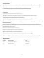
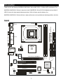
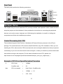
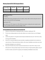
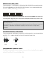
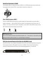
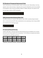
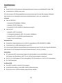
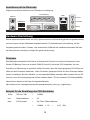
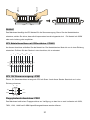
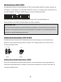
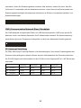
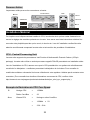
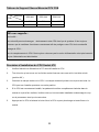
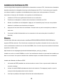
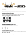
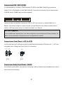
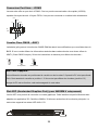
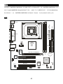
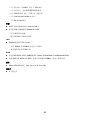
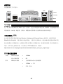
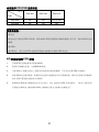
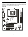
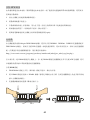
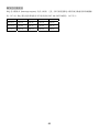
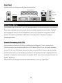
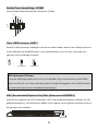
FCC-B Radio Frequency Interference Statement
This equipment has been tested and found to comply with the limits for a class B digital device, pursuant to part 15 of
the FCC rules. These limits are designed to provide reasonable protection against harmful interference when the
equipment is operated in a commercial environment. This equipment generates, uses and can radiate radio frequency
energy and, if not installed and used in accordance with the instruction manual, may cause harmful interference to
radio communications. Operation of this equipment in a residential area is likely to cause harmful interference, in
which case the user will be required to correct the interference at his own expense.
Notice 1
The changes or modifications not expressly approved by the party responsible for compliance could void the user’s
authority to operate the equipment.
Notice 2
Shielded interface cables and A.C. power cord, if any, must be used in order to comply with the emission limits.
VOIR LA NOTICE D’NSTALLATION AVANT DE RACCORDER AU RESEAU.
Micro-Star International
MS-7057
This device complies with Part 15 of the FCC Rules. Operation is subject to the following two conditions:
(1) this device may not cause harmful interference, and
(2) this device must accept any interference received, including interference that may cause undesired operation
G52-M7057X2
i
Copyright Notice
The material in this document is the intellectual property of MICRO-STAR INTERNATIONAL. We take every care in
the preparation of this document, but no guarantee is given as to the correctness of its contents. Our products are
under continual improvement and we reserve the right to make changes without notice.
Trademarks
All trademarks are the properties of their respective owners.
AMD, Athlon™ Athlon™XP, Thoroughbred™ and Duron™ are registered trademarks of AMD Corporation.
Intel® and Pentium® are registered trademarks of Intel Corporation.
PS/2 and OS® 2 are registered trademarks of International Business Machines Corporation.
Microsoft® is a registered trademark of Microsoft Corporation. Windows® 98/2000/NT/XP are registered trademarks
of Microsoft Corporation.
NVIDIA, the NVIDIA logo, DualNet, and nForce are registered trademarks or trademarks of NVIDIA Corporation in the
United States and/or other countries.
Netware® is a registered trademark of Novell, Inc.
Award® is a registered trademark of Phoenix Technologies Ltd.
AMI® is a registered trademark of American Megatrends Inc.
Kensington and MicroSaver are registered trademarks of the Kensington Technology Group.
PCMCIA and CardBus are registered trademarks of the Personal Computer Memory Card International Association.
Revision History
Revision
Revision History
Date
V1.0
First released for PCB 1.x
March 2004
V1.1
Add Dutch version
April 2004
ii
Safety Instructions
1. Always read the safety instructions carefully.
2. Keep this User Manual for future reference.
3. Keep this equipment away from humidity.
4. Lay this equipment on a reliable flat surface before setting it up.
5. The openings on the enclosure are for air convection hence protects the equipment from overheating. Do not
cover the openings.
6. Make sure the voltage of the power source and adjust properly 110/220V before connecting the equipment to the
power inlet.
7. Place the power cord such a way that people can not step on it.
Do not place anything over the power cord.
8. Always Unplug the Power Cord before inserting any add-on card or module.
9. All cautions and warnings on the equipment should be noted.
10. Never pour any liquid into the opening that could damage or cause electrical shock.
11. If any of the following situations arises, get the equipment checked by a service personnel:
- The power cord or plug is damaged.
- Liquid has penetrated into the equipment.
- The equipment has been exposed to moisture.
- The equipment does not work well or you can not get it work according to User Manual.
- The equipment has dropped and damaged.
- The equipment has obvious sign of breakage.
12. Do not leave this equipment in an environment unconditioned, storage temperature above 600 C (1400F), it may
damage the equipment.
CAUTION: Danger of explosion if battery is incorrectly replaced. Replace only with
the same or equivalent type recommended by the manufacturer.
iii
Table of Content
English.....................................................................1
Deutsch....................................................................15
Français...................................................................29
简体中文 ...................................................................43
繁體中文 ...................................................................55
Nederlands ..............................................................69
iv
Introduction
Thank you for purchasing 845GEM-V/845GVM-V Series (MS-7057) v1.X Micro ATX mainboard. The
845GEM-V/845GVM-V Series is based on Intel ® 845GE/GV & Intel ® ICH4 chipsets and provides 6
USB 2.0 ports for high-speed data transmission. With all these special designs, the
845GEM-V/845GVM-V Series delivers a high performance and professional desktop platform solution.
Layout
US B
po rts
FD D 1
AT X
Po wer Su ppl y
CP UFA N1
Top : m ous e
Bot tom : ke ybo ard
SOCKET 47 8
Top : P ara llel Por t
Bo ttom :
CO MA
VGA po rt
JP W1
J COM2
W inb on d
W83 627 HF -AW
RTL
8101L
AG P S lo t ( fo r 84 5G EM-V)
DDR 1
JCASE1
DDR 2
T: Lin e-In
M:Lin e-Ou t
B:Mic
IDE 1
T op: LAN Ja ck
B otto m: USB
p orts
IDE 2
Inte l
845G V/GE
BATT
+
P CI Sl ot 1
P CI Sl ot 2
ICH4
CD _IN1
JB AT1
Co dec
P CI Sl ot 3
BIO S
S YSFAN 1
CNR
J AUD IO 1
1
JU SB1
JFP 1
JF P2
Specifications
CPU
z
Socket 478 for P4 processors (Northwood/Prescott Celeron) at 400 MHz/533 MHz
z
Supports up to 3.06GHz or faster.
(For the latest information about CPU, please visit
http://www.msi.com.tw/program/products/mainboard/mbd/pro_mbd_cpu_support.php )
Chipset
z
Intel ® 845GE/GV
- Supports FSB 400MHz /533MHz.
- Integrated 3D/2D graphic core.
- Supports PC2700 (DDR333) technology.
z
Intel ® ICH4
- AC97 Controller Integrated.
- 6 ports Hi-Speed USB 2.0 controller, 480Mb/sec.
- Supports both ACPI and legacy APM power management.
- Legacy free support.
Main Memory
z
Supports 4 memory banks using 2 184-pin unbuffered DDR 200/266/333 DIMMs.
z
Supports up to 2GB memory size without ECC.
(For the updated supporting memory modules, please visit
http://www.msi.com.tw/program/products/mainboard/mbd/pro_mbd_trp_list.php )
Slots
z
One optional AGP (Accelerated Graphics Port) slot (for 845GEM-V only) that supports AGP 2.0
4X/2X.
z
Three PCI 2.2 32-bit Master PCI Bus slots (support 3.3V/5V PCI bus interface).
z
One CNR slot.
On-Board IDE
z
Dual IDE controllers integrated in Intel ® ICH4.
z
Supports Bus Master, Ultra DMA 33/66/100 operation modes.
z
Can connect up to four IDE devices.
On-Board Peripherals
z
On-Board Peripherals includes:
2
- 1 floppy port supports 2 FDDs with 360K, 720K, 1.2M, 1.44M and 2.88 Mbytes.
- 1 serial port (COMA) and 1 VGA port
- 1 parallel port supports SPP/EPP/ECP mode
- 6 USB 2.0/1.1 ports (Rear * 4 / Front * 2)
- 1 Line-In/Line-Out/Mic-In port
- 1 RJ-45 LAN connector
Audio
z
AC97 link controller integrated in Intel ® ICH4.
z
6 channels S/W audio codec Realtek ALC655 codec
- Compliance with AC97 2.2 Spec
- Meets PC2001 audio performance requirement
LAN
z
Realtek 8101L PCI2.2 LAN
- Supports 10Mb/s and 100Mb/s auto-negotiation operations.
- Compliance with PCI 2.2 and PC99 standard.
BIOS
z
4MB Award BIOS with PNP BIOS, ACPI, SMBIOS 2.3, Green and Boot Block.
z
Provides DMI 2.0, WFM 2.0, WOL, chassis intrusion, and SMBus for system management.
Dimension
z
Micro-ATX Form Factor: 24.4 cm (L) x 21.4 cm (W).
Mounting
z
6 mounting holes.
3
Rear Panel
The back panel provides the following connectors:
Par all el Por t
Mouse
L AN
Line In
USB Po rts
Line Ou t
Mic In
Keyb oar d
COM po rt
VG A p o rt
USB Ports
Hardware Setup
This chapter tells you how to install the CPU, memory modules, and expansion cards, as well as how to
setup the jumpers on the mainboard. It also provides the instructions on connecting the peripheral
devices, such as the mouse, keyboard, etc. While doing the installation, be careful in holding the
components and follow the installation procedures.
Central Processing Unit: CPU
The mainboard supports Intel Pentium 4 Northwood & Prescott Celeron processor in the 478 pin
package. The mainboard uses a CPU socket called PGA478 for easy CPU installation. When you are
installing the CPU, make sure the CPU has a heat sink and a cooling fan attached on the top to prevent
overheating. If you do not find the heat sink and cooling fan, contact your dealer to purchase and install
them before turning on the computer. (For the latest information about CPU, please visit
http://www.msi.com.tw/program/products/mainboard/mbd/pro_mbd_cpu_support.php )
Example of CPU Core Speed Derivation Procedure
If
then
CPU Clock
=
133MHz
Core/Bus ratio
=
23
CPU core speed
=
Host Clock x Core/Bus ratio
=
133MHz
=
3.06 GHz
x 23
4
Memory Speed/CPU FSB Support Matrix
Memory
DDR 200
DDR 266
DDR 333
400 MHz
OK
OK
Down to 266
533 MHz
OK
OK
OK
FSB
MSI Reminds You...
Overheating…
Overheating will seriously damage the CPU and system, always make sure the cooling fan can work
properly to protect the CPU from overheating.
Replacing the CPU…
While replacing the CPU, always turn off the ATX power supply or unplug the power supply’s power
cord from grounded outlet first to ensure the safety of CPU.
CPU Installation Procedures for Socket 478
1.
Please turn off the power and unplug the power cord before installing the CPU.
2.
Pull the lever sideways away from the socket. Make sure to raise the lever up to a 90-degree
angle.
3.
Look for the gold arrow. The gold arrow should point towards the lever pivot. The CPU can only
fit in the correct orientation.
4.
If the CPU is correctly installed, the pins should be completely embedded into the socket and
can not be seen. Please note that any violation of the correct installation procedures may cause
permanent damages to your mainboard.
5.
Press the CPU down firmly into the socket and close the lever. As the CPU is likely to move
while the lever is being closed, always close the lever with your fingers pressing tightly on top of
the CPU to make sure the CPU is properly and completely embedded into the socket.
5
Installing the CPU Fan
As processor technology pushes to faster speeds and higher performance, thermal management
becomes increasingly important. To dissipate heat, you need to attach the CPU cooling fan and
heatsink on top of the CPU. Follow the instructions below to install the Heatsink/Fan:
1.
Locate the CPU and its retention mechanism on the motherboard.
2.
Position the heatsink onto the retention mechanism.
3.
Mount the fan on top of the heatsink. Press down the fan until its four clips get wedged in the
holes of the retention mechanism.
4.
Press the two levers down to fasten the fan. Each lever can be pressed down in only ONE
direction.
5.
Connect the fan power cable from the mounted fan to the 3-pin fan power connector on the
board.
Memory
The mainboard provides two 184-pin unbuffered DDR200/DDR266/DDR333 SDRAM, and supports the
memory size up to 2GB. To operate properly, at least one DIMM module must be installed. (For the
updated supporting memory modules, please visit
http://www.msi.com.tw/program/products/mainboard/mbd/pro_mbd_trp_list.php )
Install at least one DIMM module on the slots. Memory modules can be installed on the slots in any
order. You can install either single- or double-sided modules to meet your own needs.
Installing DDR Modules
1.
The DDR DIMM has only one notch on the center of module. The module will only fit in the right
orientation.
2.
Insert the DIMM memory module vertically into the DIMM slot. Then push it in until the golden
finger on the memory module is deeply inserted in the socket.
3.
The plastic clip at each side of the DIMM slot will automatically close.
6
Volt
N ot ch
Power Supply
The mainboard supports ATX power supply for the power system. Before inserting the power supply
connector, always make sure that all components are installed properly to ensure that no damage will
be caused. A 300W or above power supply is suggested.
ATX 20-Pin Power Connector: CONN1
This connector allows you to connect to an ATX power supply. To connect to the ATX power supply,
make sure the plug of the power supply is inserted in the proper orientation and the pins are aligned.
Then push down the power supply firmly into the connector.
5V
5V
GN D
-5V
GN D
GN D
3 .3V
G ND
PS _ON
- 12V
20
11
10
1
1 2V
5 V_SB
GN D
P W_ OK
GN D
5V
3 .3V
G ND
5V
3 .3V
ATX 12V Power Connector: JPW1
This 12V power connector is used to provide power to the CPU.
3
4
12V
12V
GND
G ND
1
2
Floppy Disk Drive Connector: FDD1
The mainboard provides a standard floppy disk drive connector that supports 360K, 720K, 1.2M, 1.44M
and 2.88M floppy disk types.
7
Chassis Intrusion Switch Connector: JCASE1
This connector is connected to 2-pin connector chassis switch. If the Chassis is open, the switch will be
short. The system will record this status. To clear the warning, you must enter the BIOS setting and
clear the status.
GN D
CI NTRU
CD-In Connector: CD_IN1
The connector is for CD-ROM audio connector.
GN D
L
R
Fan Power Connectors: CPUFAN1/SYSFAN1
The CPUFAN1 (processor fan) and SYSFAN1 (system fan) support system cooling fan with +12V. They
support three-pin head connector. When connecting the wire to the connectors, always take note that
the red wire is the positive and should be connected to the +12V, the black wire is Ground and should
be connected to GND. If the mainboard has a System Hardware Monitor chipset on-board, you must
use a specially designed fan with speed sensor to take advantage of the CPU fan control.
+12V
GN D
SE NS OR
MSI Reminds You...
1. Always consult the vendors for proper CPU cooling fan.
2. CPUFAN1 supports the fan control. You can install the PC Alert utility that will automatically control
the CPU fan speed according to the actual CPU temperature.
8
IDE Connectors: IDE1 & IDE2
The mainboard has a 32-bit Enhanced PCI IDE and Ultra DMA 33/66/100/133 controller that provides
PIO mode 0~4, Bus Master, and Ultra DMA 33/66/100/133 function. You can connect up to four hard
disk drives, CD-ROM, 120MB Floppy and other devices.
The first hard drive should always be connected to IDE1. IDE1 can connect a Master and a Slave drive.
You must configure second hard drive to Slave mode by setting the jumper accordingly. IDE2 can also
connect a Master and a Slave drive.
MSI Reminds You...
If you install two hard disks on cable, you must configure the second drive to Slave mode by setting its
jumper. Refer to the hard disk documentation supplied by hard disk vendors for jumper setting
instructions.
Front Panel Connectors: JFP1 & JFP2
The mainboard provides two front panel connectors for electrical connection to the front panel switches
and LEDs. JFP1 is compliant with Intel Front Panel I/O Connectivity Design Guide.
Powe r
LED
P ower
S wi tch
2
1
Speak er
10
9
HDD
LED
Reset
S wi tch
JFP1
8
7
2
1
P ower
LED
JFP2
Front Panel Audio Connector: JAUD1
The JAUD1 front panel audio connector allows you to connect to the front panel audio and is compliant
with Intel ® Front Panel I/O Connectivity Design Guide.
9
AUD_V CC
AU D_G ND
A UD_RET_ R
KE Y
AUD_RET _L
2
1
10
9
AUD _FP OUT_ L
HP _ON
A UD_FP OUT_R
AU D_M IC
A UD_M IC_ BIAS
MSI Reminds You...
If you do not want to connect to the front audio header, pins 5 & 6, 9 & 10 have to be jumpered in order
to have signal output directed to the rear audio ports. Otherwise, the Line-Out connector on the back
2
panel will not function. 1
10
9
Front USB Connector: JUSB1
The mainboard provides one standard USB 2.0 pin header JUSB1. USB 2.0 technology increases data
transfer rate up to a maximum throughput of 480Mbps, which is 40 times faster than USB 1.1, and is
ideal for connecting high-speed USB interface peripherals such as USB HDD, digital cameras, MP3
players, printers, modems and the like.
US B1 US B1 +
VC C
GND
US BOC
2
1
10
9
KEY
G ND
VC C
US B0+
US B0 -
10
Serial Port Connector: JCOM2
The mainboard offers one optional serial port JCOM2. It is a 16550A high speed communication port
that sends/receives 16 bytes FIFOs. You can attach a serial device directly to it.
RT S
G ND
RI
SO UT
D CD
9
10
1
2
SIN
DTR
DSR
CTS
Clear CMOS Jumper: JBAT1
There is a CMOS RAM on board that has a power supply from external battery to keep the data of
system configuration. With the CMOS RAM, the system can automatically boot OS every time it is
turned on. If you want to clear the system configuration, use the JBAT1 (Clear CMOS Jumper) to clear
data. Follow the instructions below to clear the data:
1
1
1
3
3
K ee p Da t a
Cle a r Da ta
MSI Reminds You...
You can clear CMOS by shorting 2-3 pin while the system is off.
Then return to 1-2 pin position. Avoid
clearing the CMOS while the system is on; it will damage the mainboard.
AGP (Accelerated Graphics Port) Slot (for 845GEM-V only)
The AGP slot allows you to insert the AGP graphics card. AGP is an interface specification designed for
the throughput demands of 3D graphics. It introduces a 66MHz, 32-bit channel for the graphics
controller to directly access main memory. The mainboard supports 4x/8x 1.5V AGP card.
11
PCI (Peripheral Component Interconnect) Slots
The PCI slots allow you to insert the expansion cards to meet your needs. When adding or removing
expansion cards, make sure that you unplug the power supply first. Meanwhile, read the documentation
for the expansion card to make any necessary hardware or software settings for the expansion card,
such as jumpers, switches or BIOS configuration.
CNR (Communication Network Riser) Slot
The CNR slot allows you to insert the CNR expansion cards. CNR is a specially designed network,
audio, or modem riser card for ATX family motherboards. Its main processing is done through software
and controlled by the motherboard chipset.
PCI Interrupt Request Routing
The IRQ, abbreviation of interrupt request line and pronounced I-R-Q, are hardware lines over which
devices can send interrupt signals to the microprocessor. The PCI IRQ pins are typically connected to
the PCI bus INT A# ~ INT D# pins as follows:
Order1
Order2
Order3
Order4
PCI Slot 1
INT A#
INT B#
INT C#
INT D#
PCI Slot 2
INT B#
INT C#
INT D#
INT A#
PCI Slot 3
INT C#
INT D#
INT A#
INT B#
12
BIOS Setup
Power on the computer and the system will start POST (Power On Self Test) process. When the
message below appears on the screen, press <DEL> key to enter Setup.
DEL: Setup
F11: Boot Menu
F12: Network boot
TAB: Logo
If the message disappears before you respond and you still wish to enter Setup, restart the system by
turning it OFF and On or pressing the RESET button. You may also restart the system by
simultaneously pressing <Ctrl>, <Alt>, and <Delete> keys.
For the complete BIOS introduction and setup, please visit MSI website at http://www.msi.com.tw.
13
14
Einleitung
Vielen Dank für den Kauf des 845GEM-V/845GVM-V Serie (MS-7057) v1.X Micro ATX Mainboard. Die
845GEM-V/845GVM-V Serie basiert auf dem Intel ® 845GE/GV & Intel ® ICH4 Chipsatz und bietet 6
USB 2.0 Anschlüsse für schnellen Datentransfer. Nit diesem speziellen Design stellt die
845GEM-V/845GVM-V Serie eine proffessionelle High Performance Desktop-PC Lösung dar.
Layout
US B
po rts
FD D 1
AT X
Po wer Su ppl y
CP UFA N1
Top : m ous e
Bot tom : ke ybo ard
SOCKET 47 8
Top : P ara llel Por t
Bo ttom :
CO M A
VGA po rt
JP W1
J COM2
W inb on d
W83 627 HF -AW
RTL
8101L
AG P S lo t ( fo r 84 5G EM-V)
DDR 1
JCASE1
DDR 2
T: Lin e-In
M:Lin e-Ou t
B:Mi c
IDE 1
T op: LAN Ja ck
B otto m: USB
p orts
IDE 2
Inte l
845G V/GE
BATT
+
P CI Sl ot 1
P CI Sl ot 2
ICH4
CD _IN1
JB AT1
Co dec
P CI Sl ot 3
BIO S
S YSFAN 1
CNR
J AUD IO 1
15
JU SB1
JFP 1
JF P2
Spezifikationen
CPU
z
Sockel 478 für P4 Prozessoren (Northwood/Prescott Celeron) mit 400 MHz/533 MHz FSB
z
Unterstützt bis 3.06GHz oder mehr.
(Für die neuesten CPU-Kompatiblitäts-Informationen besuchen Sie bitte die folgende Webseite:
http://www.msi.com.tw/program/products/mainboard/mbd/pro_mbd_cpu_support.php )
Chipsatz
z
Intel ® 845GE/GV
- Unterstützt FSB 400MHz /533MHz.
- Integrierte 3D/2D Grafikkarte.
- Unterstützt PC2700 (DDR333) Speichertechnologie.
z
Intel ® ICH4
- Integrierte AC97 Soundkarte.
- 6 Hochgeschwindigkeits-USB 2.0 Controller, 480Mb/sec.
- Unterstützt ACPI und APM Energie-Management.
- Legacy Free Unterstützung.
Hauptspeicher
z
Unterstützt 4 Speicherbänke mit 2x 184-Pin ungepufferten DDR 200/266/333 DIMMs.
z
Unterstützt bis zu 2GB Speichergröße ohne ECC.
(Für die neuesten Speicher-Kompatiblitäts-Informationen besuchen Sie bitte die folgende Webseite:
http://www.msi.com.tw/program/products/mainboard/mbd/pro_mbd_trp_list.php )
Steckplätze
z
Ein optionaler AGP (Accelerated Graphics Port) Steckplatz (nur bei 845GEM-V), welcher
AGP-Karten der Spezifikation AGP 2.0 mit 4X/2X Geschwindigkeit unterstützt.
z
Drei PCI 2.2 32-bit Master PCI Bus Steckplätze (Für PCI-Karten mit 3.3V/5V PCI Schnittstelle).
z
Ein CNR Steckplatz.
On-Board IDE
z
Dual IDE Controller in Intel ® ICH4 integriert.
z
Unterstützt Bus Master, Ultra DMA 33/66/100 Betriebsmodus.
z
Es können bis zu 4 IDE-Laufwerke angeschlossen werden.
16
On-Board Peripherie
z
On-Board Peripherie beinhaltet:
- 1 Floppy Anschluss für bis zu 2 Floppylaufwerke mit 360K, 720K, 1.2M, 1.44M und 2.88 Mbytes.
- 1 serieller Anschluss (COMA) und 1 VGA Anschluss
- 1 paralleler Anschluss mit SPP/EPP/ECP Unterstützung
- 6 USB 2.0/1.1 Anschlüsse (Rückseite * 4 / Frontseite * 2)
- 1 Line-In/Line-Ausgang / Mikrophon-Eingang
- 1 RJ-45 LAN Anschluss
Audio
z
AC97 Link Controller in Intel ® ICH4 integriert.
z
6 Kanal S/W Audio Codec Realtek ALC655
- Entspricht der AC97 2.2 Spezifikation
- Entspricht den PC2001 Audio Performance Anforderungen
Netzwerk
z
Realtek 8101L PCI2.2 LAN
- Unterstützt 10Mb/s und 100Mb/s mit automatischer Transferraten-Erkennung.
- Entspricht dem PCI 2.2 und PC99 Standard.
BIOS
z
4MB Award BIOS mit PNP BIOS, ACPI, SMBIOS 2.3, Green und Boot Block.
z
Stellt DMI 2.0, WFM 2.0, WOL, Chassis Intrusion und SMBus für System Management zur
Verfügung.
Dimension
z
Micro-ATX Form Factor: 24.4 cm (Breite) x 21.4 cm (Tiefe).
Befestigung
z
6 Befestigungslöcher.
17
Anschlüsse auf der Rückseite
Folgende Anschlüsse stehen auf der Rückseite zur Verfügung:
Par all el Por t
L AN
Mouse
Line In
USB Po rts
Line Ou t
Mic In
Keyb oar d
COM po rt
VG A p o rt
USB Ports
Hardware Einrichtung
Dieses Kapitel beschreibt Ihnen, wie CPU, Speichermodule und Erweiterungskarten eingesetzt werden,
und wie Jumper auf dem Mainboard eingestellt werden. Es beinhaltet auch die Anleitung, wie Sie
Peripheriegeräte wie Maus, Tastatur, usw. anschließen. Während der Installation behandeln Sie bitte
die Komponenten vorsichtig und folgen Sie genau der Anleitung.
Prozessor
Das Mainboard unterstützt Intel Pentium 4 Northwood & Prescott und Celeron Prozessoren in der
Sockel 478 Bauform. Dazu hat es einen PGA478 Sockel für die leichte CPU Installation. Um den
Prozessor vor Überhitzung zu schützen, stellen Sie sicher, dass Sie einen geeigneten CPU-Kühler mit
Lüfter auf dem Prozessor installieren.. Wenn Sie keinen geeigneten Kühler für Ihren Prozessor haben
sollten, kontaktieren Sie Ihren Händler, um ein passendes Modell erwerben. Bitte schalten Sie den PC
nicht ein, wenn Sie keinen geeigneten Kühler installiert haben. (Für die neuesten CPU-KompatiblitätsInformationen besuchen Sie bitte die folgende Webseite:
http://www.msi.com.tw/program/products/mainboard/mbd/pro_mbd_cpu_support.php )
Beispiel für die Ermittlung des CPU-Kerntaktes
Wenn
CPU ext. Takt
=
133MHz
und
Taktmultiplikator
=
23
dann
CPU Kerntakt
=
Ext. Takt x Taktmultiplikator
=
133MHz
x 23
18
=
3.06 GHz
Speichertakt / ext. CPU Takt Tabelle
Speicher
DDR 200
DDR 266
DDR 333
400 MHz
OK
OK
Heruntergetaktet auf 266
533 MHz
OK
OK
OK
FSB
MSI erinnert Sie...
Überhitzung…
Überhitzung beschädigt Ihre CPU und ds gesamte System ernsthaft, stellen Sie daher sicher, dass die
Lüfter immer funktionieren, um die CPU und das System vor Schäden zu bewahren.
Die CPU tauschen…
Wenn Sie die CPU tauschen, schalten Sie das System ab und ziehen den Netzstecker. Bevor Sie das
Mainboard oder die CPU anfassen, erden Sie sich, in dem Sie kurz geerdeten Gegenstand (z.B.
Heizung) berühren. Dadurch vermeiden Sie Defekte an der Hardware durch statische Aufladung.
CPU Installationsprozedur für Sockel 478
1.
Bitte schalten Sie den PC aus und ziehen das Netzkabel ab, bevor Sie die CPU einsetzen.
2.
Klappen Sie den Hebel am CPU-Sockel auf. Stellen Sie sicher, dass er im 90 Grad Winkel
aufgeklappt ist.
3.
Sehen Sie den goldenen Pfeil an der CPU?. Dieser Pfeil muss zum Hebelmechanismus des
Sockels zeigen. Die CPU darf nur in der richtigen Richtung eingesetzt werden.
4.
Sobald die CPU richtig eingesetzt ist, sind die Anschlussbeine der CPU komplett im Sockel
eingesteckt. Das Einsetzen erfolgt ohne Kraftanwendung. Bitte beachten Sie, dass eine falsche
Installation des Prozessors Ihr Mainboard und Ihren Prozessor beschädigen können.
5.
Drücken Sie noch mal auf die CPU und klappen dann den Hebel herunter. Während Sie den
Hebel herunterklappen, bewegt sich die CPU noch ein wenig nach vorne. Der Hebel ist in der
Endposition, wenn er fühlbar einrastet. Der Hebel lässt sich sehr leicht bewegen. Wenn es
klemmt, prüfen Sie nochmals den korrekten Sitz der CPU.
19
Installation des CPU-Kühlers
Da die Prozessortechnologie sich mit großen Schritten bei den Taktraten und der
Arbeitsgeschwindigkeit weiterentwickelt, wird die effiziente Prozessorkühluung immer wichtiger. Um die
Wärme abzuführen, müssen Sie einen CPU-Kühler mit Lüfter auf die CPU aufsetzen. Folgen Sie der
Anleitung, um den Kühler auf die CPU aufzusetzen.:
1.
Lokalisieren Sie die CPU und den Befestigungsrahmen für den Kühler auf dem Mainboard.
2.
Setzen Sie den Kühler in den Rahmen ein.
3.
Falls erforderlich, befestigen Sie den Lüfter auf dem Kühler. Beachten Sie dabei die
Montagehinweise des Kühlerherstellers. Drücken Sie den Kühler in den Rahmen, bis er
einrastet..
4.
Drücken Sie die beiden Hebel des Kühlers herungter, bis sie einrasten. Bitte beachten Sie dabei
die Hinweise des Kühlerherstellers.
5.
Schliessen Sie das Versorgungskabel des Lüfters an dem 3-poligen Anschluss des Mainboards
an. Er ist mit CPUFAN1 beschriftet.
Speicher
Das Mainboard stellt zwei Sockel für 184-pin ungepufferte DDR200/DDR266/DDR333 DDR SDRAM
Module mit einer maximalen Gesamtspeicherkapazität von 2GB zur Verfügung. Damit das System
funktioniert, muss mindestens ein DIMM Modul eingesetzt werden. Sie können sowohl einseitige oder
zweiseitige Module in beliebiger Reihenfolge einsetzen. (Für die neuesten
Speicher-Kompatiblitäts-Informationen besuchen Sie bitte die folgende Webseite:
http://www.msi.com.tw/program/products/mainboard/mbd/pro_mbd_trp_list.php )
Speichermodule einsetzen
1.
Das DDR DIMM Modul hat in der Mitte eine Nase, die verhindern soll, dass Sie das Modul in der
falschen Richtung einsetzen.
2.
Setzen Sie das Modul senkrecht in den Sockel ein, bis die goldenen Kontakte komplett im
Sockel versinken.
3.
Die weißen Verriegelungshebel an der Seite schließen sich automatisch und rasten ein.
20
Volt
N ot ch
Netzteil
Das Mainboard benötigt ein ATX-Netzteil für die Stromversorgung. Bevor Sie den Netzteilstecker
einsetzen, stellen Sie sicher, dass alle Komponenten korrekt eingesetzt sind. Ein Netzteil mit 300W
oder mehr Leistung wird empfohlen.
ATX Netzteilanschluss mit 20Kontakten: CONN1
An diesem Anschluss schließen Sie das Netzteil an. Der Netzteilstecker lässt sich nur in einer Richtung
einstecken. Drücken Sie den Stecker in den Anschluss, bis er einrastet.
5V
5V
GND
-5V
GND
GN D
3 .3V
G ND
PS _ON
- 1 2V
20
11
10
1
1 2V
GN D
5 V_SB
P W_OK
GN D
5V
3.3V
G ND
5V
3 .3V
ATX 12V Stromversorgung: JPW1
Dieser 12V Stromanschluss versorgt die CPU mit Strom. Auch dieser Stecker lässt sich nur in eine
Richtung einsetzen.
3
4
12V
12V
GND
G ND
1
2
Floppylaufwerk-Anschluss: FDD1
Das Mainboard stellt einen Floppyanschluss zur Verfügung, an dem bis zu zwei Laufwerke mit 360K,
720K, 1.2M, 1.44M und 2.88M Kapazität angeschlossen werden können.
21
Anschluss für Chassis Intrusion Schalter: JCASE1
An diesem 2-Pin Anschluss können Sie einen Gehäuseschalter anschließen. Wenn das Gehäuse
geöffnet wird, schließt der Schalter. Das System wird sich diesen Status merken. Sie könnne die damit
zusammen hängende Warnung des BIOS im BIOS-Setup wieder zurücksetzen..
GN D
CI NTRU
CD-Audio-Eingang: CD_IN1
Hier können Sie das Audiokabel Ihres CD-Laufwerks anschließen.
GN D
L
R
Stromanschluss für Lüfter: CPUFAN1/SYSFAN1
Die Anschlüsse CPUFAN1 (CPU-Lüfter) und SYSFAN1 (System Lüfter) sind für Lüfter mit einer
Betriebsspannung von +12V geeignet. Es werden Lüfter mit 3-poligem Stecker unterstützt. Bitte
beachten Sie, dass die rote Ader des Lüfterkabels mit 12V und die schwarze Ader des Kabels mit
Masse (GND) verbinden. Das Mainboard unterstützt über das Sensor-Signal das Auslesen der
Drehzahl des Lüfters.
+12V
GN D
SE NS OR
MSI erinnert Sie...
1. Verwenden Sie stets einen geeigneten CPU-Lüfter und beachten Sie die Einbauhinweise in diesem
Handbuch und in der Lüfterdokumentation.
2. CPUFAN1 unterstützt die Geschwindigkeitsregelung des Prozessorlüfters. Sobald Sie von der
Treiber-CD das Windows-Programm PC-Alert installiert haben, wird diese Regelung aktiviert.
PC-Alert regelt die Lüfterdrehzahl anhand der CPU-Temperatur.
22
IDE Anschlüsse: IDE1 & IDE2
Das Mainboard hat einen 32-bit erweiterten PCI IDE und Ultra DMA 33/66/100 Controller, welcher die
PIO Modis 0~4, Bus Master, und Ultra DMA 33/66/100 Funktion zur Verfügung stellt. Sie können bis zu
vier IDE-Festplatten, CD-ROM, 120MB Floppys und andere Geräte anschließen.
Das erste Laufwerk sollte an IDE1 angeschlossen werden. IDE1 unterstützt Master und
Slave-Laufwerke. Auch IDE2 unterstützt Master und Slave Laufwerke.
MSI erinnert Sie...
Wenn Sie zwei IDE-Laufwerke an einem IDE-Kabel anschließen, so müssen Sie das erste Laufwerk
als Master und das zweite Laufwerk als Slave konfigurieren. Sie erfahren aus der Dokumentation der
Laufwerke, wie diese Einstellung gemacht wird.
Gehäusefront-Anschlüsse: JFP1 & JFP2
Das Mainboard hat Anschlüsse für Bedienelemente und Statusanzeigen an der Vorderseite des
gehäuses. Hierzu gehören Anzeige LEDs und Taster. JFP1 entspricht dem “Intel Front Panel I/O
Connectivity Design Guide”.
Powe r
LED
P ower
S wi tch
2
1
Speak er
10
9
HDD
LED
8
7
2
1
Reset
S wi tch
JFP1
P ower
LED
JFP2
Gehäusefront Audio-Anschluss: JAUD1
Der JAUD1 Gehäusefront-Anschluss erlaubt es Ihnen, Audio-Anschlüsse an der Vorderseite Ihres
Gehäuses mit dem Mainboard zu verbinden. Der Anschluss entspricht dem “Intel ® Front Panel I/O
Connectivity Design Guide”.
23
AUD_V CC
AU D_G ND
A UD_RET_ R
KE Y
AUD_RET _L
2
1
10
9
AUD _FP OUT_ L
HP _ON
A UD_FP OUT_R
AU D_M IC
A UD_M IC_ BIAS
MSI erinnert Sie...
Wenn Sie diesen Audioanschluss nicht verwenden möchten, so müssen die Kontakte 5 & 6, 9 & 10
jeweils mit einem Jumper geschlossen sein, damit der hintere Audio-Ausgang des Mainboards
2
funktioniert.. 1
10
9
Gehäusefront USB Anschluss: JUSB1
Das Mainboard stellt einen Standard USB 2.0 Anschluss zur Verfügung JUSB1. USB 2.0 Technologie
bietet eine erhöhte Datentransferrate von maximal 480Mbps, was 40 mal so schnell wie USB 1.1 ist,
und ist ideal, um Hochgeschwindkeits-USB-Geräte anzuschließen.
US B1 US B1 +
VC C
GND
US BOC
2
1
10
9
KEY
G ND
VC C
US B0+
US B0 -
Serieller Anschluss: JCOM2
Das Mainboard bietet einen optionalen seriellen Anschluss JCOM2. Das ist eine 16550A
Hochgeschwindigkeitsschnittstelle, welche mit 16 Byte FIFOs arbeitet. Sie können hier direkt serielle
Geräte anschließen.
24
RT S
G ND
RI
SO UT
D CD
9
10
1
2
SIN
DTR
DSR
CTS
CMOS Rücksetz-Jumper: JBAT1
Im Mainboard ist ein CMOS Speicher integriert, welches von einer Batterie versorgt wird, um die
Systemkonfiguration zu speichern. Das CMOS RAM ermöglicht es, das System automatisch zu starten,
ohne dass die Konfiguration neu eingestellt werden muss. Wenn Sie die CMOS-Konfiguration löschen
wollen, setzen Sie im ausgeschalteten Zustand den Jumper JBAT1 von Position 1-2 auf 2-3 um.
1
1
3
K ee p Da t a
1
3
Cle a r Da ta
MSI erinnert Sie...
Schalten Sie den PC vor dem Umsetzen des Jumpers aus. Setzen Sie den Jumper nach ein paar
Sekunden wieder in 1-2 zurück und schalten erst dann den PC wieder ein. Eine andere
Vorgehensweise kann das Mainboard ernsthaft beschädigen.
AGP (Accelerated Graphics Port) Steckplatz (Nur bei 845GEM-V)
In den AGP Steckplatz können Sie eine AGP-Grafikkarte einsetzen. AGP ist eine Schnittstelle, deren
Spezifikation für den Datendurchsatz von schnellen 3D-Grafuikkarten entwickelt wurde. AGP
ermöglicht 66MHz, 64-Bit Datenübertragung für den Grafik-Kontroller direkt zum Hauptspeicher. Das
Mainboard unterstützt AGP-Grafikkarten mit 4x/8x Übertragung und 1.5V AGP Betriebsspannung.
PCI (Peripheral Component Interconnect) Steckplätze
Ein PCI Steckplatz erlaubt es Ihnen, für Sie erforderliche PCI-Erweiterungskarten in das System
25
einzusetzen. Wenn Sie Erweiterungskarten einsetzen oder entfernen, stellen Sie sicher, dass Sie
vorher den PC ausschalten und den Netzstecker abziehen. Lesen Sie auch die Dokumentation der
Erweiterungskarte bezüglich Hinweisen des Herstellers zum Einbau und möglichen Hardware- und
Softwareeinstellungen.
CNR (Communication Network Riser) Steckplatz
Der CNR Steckplatz ermöglicht den Einbau von CNR Erweiterungskarten. CNR wurde speziell für
Netzwerk- Audio- oder Modem-Riserkarten für ATX-Mainboards entwickelt. Die Datenverarbeitung
dieser Karten wird durch Programme durchgeführt und durch den Mainboard-Chipsatz gesteuert.
PCI Interrupt Verteilung
Die IRQs, Abkürzung für Interrupt Request, sind Hardwaresignale, über welche Peripheriegeräte dem
Prozessor Interrupt-Signale zusenden können, wenn sie Aufmerksamkeit des Prozessors brauchen.
Die PCI IRQ Signale sind üblicherweise auf dem PCI-Bus mit den Signalen INT A# ~ INT D# wie folgt
verbunden:
Reihenfolge 1
Reihenfolge 2
Reihenfolge 3
Reihenfolge 4
PCI
Steckplatz 1
INT A#
INT B#
INT C#
INT D#
PCI
Steckplatz 2
INT B#
INT C#
INT D#
INT A#
PCI
Steckplatz 3
INT C#
INT D#
INT A#
INT B#
26
BIOS Setup
Wenn Sie den PC einschalten, startet er zuerst die POST-Systemdiagnose (Power On Self Test).
Wenn die folgende Meldung angezeigt wird, dann drücken Sie die Taste <Entf> um in das BIOS-Setup
zu gelangen.
DEL: Setup
F11: Boot Menu
F12: Network boot
TAB: Logo
Wenn die Meldung verschwindet, bevor Sie die Taste gedrückt haben, wird es das installierte
Betriebssystem starten. Wenn Sie doch ins BIOS-Setup wollen, so schalten Sie den PC aus und wieder
an, oder drücken den Reset-Knopf, um es erneut zu versuchen. Alternativ können Sie den Neustart des
Systems auch durch das gleichzeitige Drücken der Tasten <STRG>, <Alt>, and <Entf> auslösen.
Die komplette Anleitung zum BIOS-Setup finden Sie auf http://www.msi.com.tw.
27
28
Introduction
Félicitation vous venez d’acheter la carte mère Micro ATX 845GEM-V/845GVM-V (MS-7057) v1.X. La
845GEM-V/845GVM-V est basée sur les chipsets Intel ® 845GE/GV & Intel ® ICH4 vous procurant
ainsi 6 ports USB 2.0 pour une plus grande vitesse de transport des données. La
845GEM-V/845GVM-V est conçue pour vous apporter de hautes performances, faisant de cette carte
une plateforme prévue pour des applications professionnelles.
Schéma
US B
po rts
FD D 1
AT X
Po wer Su ppl y
CP UFA N1
Top : mous e
Bot tom: ke ybo ard
SOCKET 47 8
Top : P ara llel Por t
Bo ttom:
CO M A
VGA po rt
JP W1
J COM2
W inb on d
W83 627 HF -AW
RTL
8101L
AG P S lo t ( fo r 84 5G EM-V)
DDR 1
JCASE1
DDR 2
T: Lin e-In
M:Lin e-O u t
B:Mic
IDE 1
T op: LAN Ja ck
B otto m: USB
p orts
IDE 2
Inte l
845G V/GE
BATT
+
P CI Slot 1
P CI Slot 2
ICH4
CD _IN1
JB AT1
Co dec
P CI Slot 3
BIO S
S YSFAN 1
CNR
J AUD IO 1
29
JU SB1
JFP 1
JF P2
Spécifications
CPU
z
Socket 478 pour processeurs P4 (Northwood/Prescott Celeron) 400 MHz/533 MHz
z
Supporte jusqu’à 3.06GHz et au delà.
Pour connaître les dernières informations concernant le CPU, veuillez visiter
http://www.msi.com.tw/program/products/mainboard/mbd/pro_mbd_cpu_support.php )
Chipset
z
Intel ® 845GE/GV
- Supporte les FSB 400MHz /533MHz.
- Core graphique intégré 3D/2D.
- Supporte la technologie PC 2700 (DDR333).
z
Intel ® ICH4
- Contrôleur intégré AC97.
- Contrôleur pour 6 ports USB 2.0, 480Mb/sec.
- Supporte à la fois l’ACPI et l’APM power management..
Mémoire Principale
z
Supporte 4 banques de mémoire utilisant 2 unbuffered DDR 200/266/333 DIMMs 184-pin.
z
Supporte jusqu’à 2GB de mémoire non ECC.
(Pour ue mise à jour de la liste des mémoires supportées, veuillez visiter
http://www.msi.com.tw/program/products/mainboard/mbd/pro_mbd_trp_list.php )
Slots
z
Un slot AGP (Accelerated Graphics Port) optionnel (pour 845GEM-V uniquement) qui supporte
l’AGP 2.0 4X/2X.
z
Trois slots PCI 2.2 32-bit Master PCI Bus (supporte le bus d’interface 3.3V/5V).
z
Un slot CNR.
IDE Intégré
z
Double contrôleur IDE intégré dans l’Intel ® ICH4.
z
Supporte les modes opératoires Bus Master, Ultra DMA 33/66/100.
z
Possibilité de connecter jusqu’à quatre matériels IDE.
Périphériques Intégrés
z
Les périphériques intégrés sont :
- 1 port floppy supportant 2 lecteurs FDDs : 360K, 720K, 1.2M, 1.44M et 2.88 Mbytes.
30
- 1port série (COMA) et 1 port VGA
- 1 port parallèle supportant les modes SPP/EPP/ECP
- 6 ports USB 2.0/1.1 (Arrière * 4 / Façade * 2)
- 1 port Line-In/Line-Out/Mic-In
- 1 connecteur réseau RJ-45
Audio
z
Contrôleur AC97 link intégré dans l’Intel ® ICH4.
z
6 canaux audio S/W, codec Realtek ALC655
- Compatible avec les spécifications de l’AC97 2.2
- Répond aux exigences audio PC2001
Réseau
z
Réseau Realtek 8101L PCI2.2
- Supporte le 10Mb/s et le 100Mb/s (auto-négociation).
- Compatible avec le standard PCI 2.2 et PC99.
BIOS
z
BIOS Award 4MB avec PNP BIOS, ACPI, SMBIOS 2.3, Vert et Boot Block.
z
Procurant DMI 2.0, WFM 2.0, WOL, chassis intrusion, et SMBus pour le “system management“.
Dimensions
z
Fomat Micro-ATX : 24.4 cm (L) x 21.4 cm (W).
Montage
z
6 trous de montage.
31
Panneau Arrière
La panneau arrière procure les connecteurs suivants :
Par all el Port
Mouse
LAN
Line In
USB Ports
Line Ou t
Mic In
Keyboar d
COM po rt
VG A p ort
USB Ports
Installation Matériel
Ce chapitre vous indique comment installer le CPU, la mémoire ainsi que les cartes d’extension ou
encore le réglage des cavaliers présents sur la carte. Vous aurez aussi des instructions relatives à la
connexion des périphériques tels que la souris, le clavier etc. Lors de l’installation veuillez faire très
attention aux éléments composant la carte mère et suivez bien les procédure d’installations.
CPU : Central Processing Unit
La carte mère supporte les processeurs Intel Pentium 4 Northwood & Prescott Celeron (478 pin
package). La carte mère utilise un socket processeur appelé PGA478 permettant une installation aisée.
Lors de l’installation du CPU, assurez-vous que le CPU possède bien un système de refroidissement
constitué d’un dissipateur + ventilateur permettant la dissipation de la chaleur. Pour connaître le
modèle de ventilateur nécessaire à la bonne utilisation de votre système n’hésitez pas à contacter votre
revendeur. (Pour connaître les dernières informations concernant le CPU, veuillez visiter
http://www.msi.com.tw/program/products/mainboard/mbd/pro_mbd_cpu_support.php )
Exemple de Dériviation du CPU Core Speed
Si
Alors
Horloge CPU
=
133MHz
Ration Core/Bus
=
23
Vitesse CPU
=
Horloge x ration Core/Bus
=
133MHz
=
3.06 GHz
x 23
32
Tableau de Support Vitesse Mémoire/CPU FSB
Mémoire
DDR 200
DDR 266
DDR 333
400 MHz
OK
OK
Baisse à 266
533 MHz
OK
OK
OK
FSB
MSI vous rappelle...
Surchauffe…
La surchauffe peut endommager
sérieusement votre CPU ainsi que le système. Il faut toujours
s’assurer que le ventilateur fonctionne correctement afin de protéger votre CPU de la surchauffe.
Changer le CPU…
Lors du remplacement du CPU il faut toujours s’assurer que le cordon d’alimentation n’est plus branché
ou que l’alimentation est bien éteinte.
Procédure d’Installation du CPU Socket 478
1.
Veuillez éteindre ou débrancher le PC avant d’installer le CPU.
2.
Tirer le levier qui se trouve sur le côté du socket. Assurez-vous que celui-ci est bien relevé
(position 90°).
3.
Chercher la marque dorée sur le CPU. La marque dorée doit pointer vers le pivot du levier. Le
CPU peut ne s’installer que dans une seule position.
4.
Si le CPU est correctement installé, les pattes doivent être complètement insérées dans le
socket et ne plus être visibles. Veuillez noter qu’une mauvaise installation endommage à coup
sur le processeur ainsi que la carte mère.
5.
Appuyer sur le CPU et baisser le levier. Ainsi le CPU ne peut plus bouger et reste fixe sur le
socket.
33
Installation du Ventilateur de CPU
La technologie faisant augmenter rapidement la vitesse des nouveaux CPU, il devient donc nécessaire
de prêter attention à la dissipation thermique (refroidissement du CPU). C’est la raison pour laquelle
vous devez installer un système de refroidissement en phase avec votre processeur. Suivez les
instructions ci dessous afin d’installer votre système de refroidissement :
1.
Localiser le CPU et son système de rétention sur la carte mère.
2.
Positionner le dissipateur au dessus du mécanisme de rétention du CPU.
3.
Monter le ventilateur sur le dissipateur. Appuyer sur l’ensemble jusqu’à ce que vous puissiez
attacher le ventilateur au mécanisme de rétention.
4.
Appuyer sur les deux leviers du ventilateur. Chaque levier ne peut se manipuler que dans un
seul sens.
5.
Connecter le câble d’alimentation sur le connecteur de la carte mère prévu à cet effet (3
broches).
Mémoire
La carte mère offre deux slots mémoire unbuffered DDR200/DDR266/DDR333 DDR SDRAM, et
supporte 2GB de mémoire. Pour fonctionner correctement le système nécessite la mise en place d’au
moins une barrette de mémoire sur un des slots DIMM. (Pour une mise à jour des modules de mémoire
supportés, veuillez visiter
http://www.msi.com.tw/program/products/mainboard/mbd/pro_mbd_trp_list.php )
Installer au moins un module DIMM sur un slot. Les modules de mémoire ne peuvent être installés que
dans un seul sens. Vous pouvez installer des modules simples ou doubles faces selon vos besoins.
Installer des Modules de Mémoire DDR
1.
La barrette de DDR possède une seule encoche au centre. Vous ne pouvez ainsi réaliser de
mauvais montage.
2.
Insérer le module DIMM verticalement dans le slot mémoire. Puis appuyer jusqu’à ce que la
marque dorée disparaisse dans le slot mémoire.
3.
Les clips en plastique de chaque côté se ferment automatiquement.
34
Volt
N ot ch
Alimentation
La carte mère supporte les alimentations ATX. Avant de brnacher le connecteur d’alimentation. Il faut
toujours vous assurer que tous les composants sont bien installés afin de ne pas les endommager. Une
alimentation 300W ou supérieur est préconisée.
Connecteur ATX 20 broches : CONN1
Ce connecteur vous permet de connecter l’alimentation ATX. Pour ce faire assurez-vous que le
connecteur est bien positionné dans le bon sens. Puis appuyer sur le câble.
5V
5V
GN D
-5V
GN D
GN D
3 .3V
G ND
PS _ON
- 12 V
20
11
10
1
1 2V
5V_ SB
GN D
P W_ OK
GN D
5V
3 .3V
G ND
5V
3 .3V
Connecteur d’Alimentation ATX 12V : JPW1
Le connecteur d’alimentation 12V est utilisé pour alimenter le CPU.
3
4
12V
12V
GND
G ND
1
2
Connecteur Floppy Disk Drive : FDD1
La carte offre un connecteur standard floppy disk drive (lecteur de disquette) qui supporte les disques
360K, 720K, 1.2M, 1.44M et 2.88M.
35
Connecteur Chassis Intrusion Switch : JCASE1
Ce connecteur est relié au connecteur 2 broches “chassis switch”. Si le chassis est ouvert, alors le
système va mettre en mémoire cette opération. Pour effacer cette alerte vous devez entrer dans le Bios
et effacer cette donnée.
GN D
CI NTRU
Connecteur CD-In : CD_IN1
Le connecteur est déstiné au branchement audio du CD-ROM.
GN D
L
R
Connecteurs d’Alimentation de Ventilateurs : CPUFAN1/SYSFAN1
Le CPUFAN1 (ventilateur processeur) et SYSFAN1 (ventilateur système) supportent le +12V. Ils
acceptent des connecteurs 3 broches. Lors de la connexion du câble, assurez-vous que le fil rouge soit
connecté au +12V et le fil noir connecté au “GND“. Si la carte mère possède un système de gestion
intégré, vous devez utiliser un ventilateur ayant ces caractéristiques si vous voulez contrôler le
ventilateur du CPU.
+12V
GN D
SE NS OR
MSI Vous Rappelle...
1. Toujours consulter le vendeur pour connaître le ventilateur à utiliser pour le CPU.
2. CPUFAN1 supporte le contrôle du ventilateur. Vous pouvez installer l’utilitaire PC Alert qui contrôle
automatiquement la vitesse de rotation du ventilateur du CPU en fonction de la température du CPU.
36
Connecteurs IDE : IDE1 & IDE2
*La carte possède un contrôleur 32-bit Enhanced PCI IDE et Ultra DMA 33/66/100 qui procure les
modes PIO 0~4, Bus Master, et Ultra DMA 33/66/100. Vous pouvez connecter jusqu’à 4 disques durs,
CD-ROM, lecteur 120MB Floppy ou autres matériels.
Le premier disque dur doit être connecté sur l’IDE1. L’IDE1 peut recevoir un matériel Maître et un
Esclave. Vous devez configurer le second disque en mode Esclave et ce à l’aide du cavalier situé à
l’arrière. L’IDE2 peut aussi recevoir un matériel en Maître et en Esclave.
MSI Vous Rappelle...
Si vous installez deux disques durs, vous devez configurer le second disque en Esclave (cavalier). Se
référer à la documentation du disque dur pour la configuration du cavalier.
Connecteurs Front Panel : JFP1 & JFP2
La carte mère procure 2 connecteurs pour les branchements électriques (LED disque dur…). JFP1 est
compatible avec le Design Intel Front Panel I/O Connectivity.
Powe r
LED
P ower
S wi tch
2
1
Speak er
10
9
HDD
LED
8
7
2
1
Reset
S wi tch
JFP1
P ower
LED
JFP2
Connecteur Audio Front Panel : JAUD1
Le connecteur audio JAUD1 vous permet de connecter l’audio en façade et est compatible avec l’ntel ®
Front Panel I/O Connectivity.
37
AUD_V CC
AU D_G ND
A UD_RET_ R
KE Y
AUD_RET _L
2
1
10
9
AUD _FP OUT_ L
HP _ON
A UD_FP OUT_R
AU D_M IC
A UD_M IC_ BIAS
MSI Vous Rappelle...
Si vous ne voulez pas connecter l’audio en façade à l’aide des broches 5 & 6, 9 & 10 doivent être
recouvertes par un cavalier pour envoyer le signal vers les ports audio à l’arrière. Autrement, le
2
connecteur Line-Out à l’arrière ne fonctionnera pas. 1
10
9
Connecteur USB en Façade : JUSB1
La carte procure un connecteur standard USB 2.0 (JUSB1). La technologie USB 2.0 permet d’accroître
le taux de transfert des données par 40 par rapport à l’USB 1.1. L’USB 2.0 est idéal pour connecter une
caméra, un appareil photo ou encore une imprimante.
US B1 US B1 +
VC C
GND
US BOC
2
1
10
9
KEY
G ND
VC C
US B0+
US B0 -
38
Connecteur Port Série : JCOM2
La carte mère offre un port série JCOM2. C’est un port de communication ultra rapide (16550A)
capable d’envoyer/recevoir 16 bytes FIFOs. Vous pouvez connecter un matériel série directement.
RT S
G ND
RI
SO UT
D CD
9
10
1
2
SIN
DTR
DSR
CTS
Cavalier Clear CMOS : JBAT1
La batterie (pile) permet à la mémoire CMOS RAM de retenir les modifications que vous faites dans le
BIOS. Si vous voulez effacer les informations stockées dans cette mémoire vous devez utiliser le
JBAT1 (Clear CMOS Jumper). Suivez les instructions ci-dessous pour effacer les données :
1
1
3
K ee p Da t a
1
3
Cle a r Da ta
MSI Vous Rappelle...
Vous effacez les données en positionnant le cavalier sur les broches 2-3 quand le PC n’est pas allumé.
Puis il faut remettre le cavalier en position 1-2. Ne surtout pas effacer les données (position 2-3)
lorsque le PC est en fonction, cela endommagerait la carte mère.
Slot AGP (Accelerated Graphics Port) (pour 845GEM-V uniquement)
Le slot AGP vous permet de connecter une carte graphique. Cette interface est particulièrement bien
adaptée aux application 3D. Contrôleur 66MHz, 32-bit avec accès direct à la mémoire principale. La
carte mère supporte les cartes AGP 4x/8x 1.5V.
39
Slots PCI (Peripheral Component Interconnect)
Les slots PCI vous permettent la connexion de cartes d’extension selon vos besoins. Pour installer ou
retirer une carte PCI, il faut que le PC soit éteint. Si la carte PCI nécessite des réglages, veuillez vous
reporter à la documentation fournie avec cette dernière.
Slot CNR (Communication Network Riser)
Le slot accepte les cartes CNR et permet la connexion de cartes Modem, réseau etc. La carte CNR est
contrôlée par le chipset de la carte mère.
PCI Interrupt Request Routing
IRQ est l’abréviation de “interrupt request line”. Les IRQ sont des signaux émis par des matériels. Les
PCI IRQ sont connectés généralement au PCI bus INT A# ~ INT D# pins comme suit :
Order1
Order2
Order3
Order4
PCI Slot 1
INT A#
INT B#
INT C#
INT D#
PCI Slot 2
INT B#
INT C#
INT D#
INT A#
PCI Slot 3
INT C#
INT D#
INT A#
INT B#
40
Setup du BIOS
Lorsque le PC démarre le processus de POST (Power On Self Test) se met en route. Quand le
message ci-dessous apparaît, appuyer sur <DEL> pour accéder au Setup.
DEL: Setup
F11: Menu de Boot
F12: Boot réseau
TAB: Logo
Si le message disparaît avant que n’ayez appuyé sur la touche, redémarrez le PC à l’aide du bouton
RESET. Vous pouvez aussi redémarrer en utilisant la combinaison de touches <Ctrl>, <Alt>, et
<Delete>.
Pour de plus amples informations sur le BIOS, veuillez visiter le site web de MSI :
http://www.msi.com.tw.
41
42
简介
感谢您购买 845GEM-V/845GVM-V 系列(MS-7057) v1.X Micro ATX 主板。845GEM-V/845GVM-V 系列
是基于 Intel ® 845GE/GV & Intel ® ICH4 芯片组,且提供了 6 个 USB 2.0 端口,以实现高速数据传输。
集多种特性于一体, 845GEM-V/845GVM-V 系列提供了高性能、专业化的桌面平台解决方案。
布局
USB
p or ts
FDD 1
ATX
P ow er S upply
CPUFAN1
To p : m ouse
Bottom : k ey boa rd
SO CKET 4 78
To p : P aral l el Port
Bott om:
COM A
VG A port
J PW1
JCOM 2
Wi nbond
W8 36 27 HF-AW
RTL
81 01L
A GP Slot ( for 845GEM-V)
DDR 1
JC AS E1
DDR 2
T:Line-In
M:Li ne -O ut
B: Mic
IDE 2
To p: LAN J ac k
Bott om: US B
port s
IDE 1
I nt el
845 GV/ GE
BATT
+
PCI S lo t 1
PCI S lo t 2
I C H4
C D_ IN 1
JBAT1
Code c
PCI S lo t 3
BIO S
SYS FAN1
CNR
J AUDI O1
43
J USB1
J FP 1
JFP 2
规格
CPU
z
支持 Socket 478 的 P4 处理器 (Northwood/Prescott Celeron),工作频率为 400 MHz/533 MHz
z
最高支持到 3.06GHz 或更快的处理器
(要了解关于 CPU 的最新信息,请访问
http://www.msi.com.tw/program/products/mainboard/mbd/pro_mbd_cpu_support.php )
芯片组
z
Intel ® 845GE/GV
- 支持 FSB 400MHz /533MHz
- 集成了 3D/2D 图形核心
- 支持 PC2700 (DDR333)技术
z
Intel ® ICH4
- 集成了 AC97 控制器
- 6 个高速 USB 2.0 控制器,速度为 480Mb/sec
- 支持 ACPI 和 legacy APM 电源管理
- 无需现用支持
主内存
z
支持 2 条双面的 184-pin 无缓冲的 DDR 200/266/333 DIMMs
z
最高支持到 2GB 的无 ECC 内存容量
(要了解内存模组支持的更新详情,请访问
http://www.msi.com.tw/program/products/mainboard/mbd/pro_mbd_trp_list.php )
插槽
z
1 条选配的 AGP(加速图形端口)插槽(仅对于 845GEM-V)
,支持 AGP 2.0 4X/2X
z
3 条 PCI 2.2 32-bit Master PCI 总线插槽(支持 3.3V/5V PCI 总线界面)
z
1 条 CNR 插槽
半载 IDE
z
双 IDE 控制器集成于 Intel ® ICH4 中
z
支持 Bus Master, Ultra DMA 33/66/100 工作模式
z
最多可连接 4 个 IDE 设备
半载周边
z
板载周边包括:
- 1 个软驱接口,支持 2 台 360K, 720K, 1.2M, 1.44M and 2.88 Mbytes 的软驱
44
- 1 个串行端口(COMA)和 1 个 VGA 端口
- 1 个并行端口,支持 SPP/EPP/ECP 模式
- 6 个 USB 2.0/1.1 端口(后置* 4 / 前置* 2)
- 1 个 Line-In/Line-Out/Mic-In 端口
- 1 个 RJ-45 LAN 接口
音频
z
AC97 连接控制器集成于 Intel ® ICH4 中
z
6 声道 S/W 音频编解码 Realtek ALC655
- 符合 AC97 2.2 规格
- 满足 PC2001 音频性能要求
LAN
z
Realtek 8101L PCI2.2 LAN
- 支持 10Mb/s 和 100Mb/s 自适应工作模式
- 兼容 PCI 2.2 和 PC99 标准
BIOS
z
带有 PNP BIOS, ACPI, SMBIOS 2.3, Green 和 Boot Block 的 4MB Award BIOS
z
提供 DMI 2.0, WFM 2.0, WOL, 机箱入侵侦测和 SMBus,以便于系统管理
规格
z
Micro-ATX 规格结构:24.4 cm (L) x 21.4 cm (W)
固定孔
z
6 个固定孔
45
后置面板
后置面板提供了以下接口:
Par all el Por t
Mouse
L AN
Line In
USB Po rts
Line Ou t
Mic In
Keyb oar d
COM po rt
VG A p o rt
USB Ports
硬件设置
这一章主要告诉您如何安装 CPU,内存,扩展卡,也会告诉您怎样设置主板上的跳线,并提供连接外围
设备的指导,如鼠标,键盘等。安装时,请谨慎拿各零部件并且按照安装说明的步骤进行。
中央处理器:CPU
本主板支持 478 针脚封装的 Intel Pentium 4 Northwood & Prescott Celeron 处理器。主板使用的是
PGA478 的 CPU 插槽,可使 CPU 安装过程简化。当您在安装 CPU 时,请务必确认您使用的 CPU 带有
防过热的散热片和降温风扇。如果您的 CPU 没有散热片和降温风扇,请与销售商联系,购买或索取以上
设备,并在开机之前妥善安装。(要了解关于 CPU 的最新信息,请访问
http://www.msi.com.tw/program/products/mainboard/mbd/pro_mbd_cpu_support.php )
CPU 核心速度推导
如果
那么
CPU 时钟频率
=
133MHz
核心/总线倍频
=
23
CPU 核心频率
=
主时钟频率 x 核心/总线倍频
=
133MHz
=
3.06 GHz
x 23
46
内存速率/CPU FSB 支持列表
内存
DDR 200
DDR 266
DDR 333
400 MHz
OK
OK
降低到 266
533 MHz
OK
OK
OK
FSB
微星提醒您...
温度过高
温度过高会严重损害 CPU 和系统,请务必确认所使用的降温风扇始终能够正常工作,保护 CPU 以免过
热烧毁。
更换 CPU
更换 CPU 时,请先关闭 ATX 电源供应或拔掉电源插头以确保 CPU 的安全。
478 针脚封装的 CPU 安装
1.
安装前请先关掉电源并且拔掉电源线。
2.
将拉杆从插槽上拉起,与插槽成 90 度角。
3.
寻找 CPU 上的圆点/切边。此圆点/切边应指向拉杆的旋轴,只有方向正确 CPU 才能插入。
4.
如果 CPU 是正确安装的,针脚应该完全嵌入进插座里并且不能被看到。请注意任何违反正确操作
的行为都可能导致主板的永久性破坏。
5.
稳固的将 CPU 插入到插座里并且关上拉杆。当拉上拉杆时 CPU 可能会移动,一般关上拉杆时用
手指按住 CPU 的上端以确保 CPU 正确的而且是完全的嵌入进插座里了。
47
安装 CPU 风扇
在新技术的推动下,使处理器可以运行在更高的频率下,速度更快,效能更好,热量的控制也变得越来
越重要。为了驱散热量,您应在 CPU 上方安装合适的散热片和降温风扇。请按照以下步骤完成散热片和
风扇的安装:
1.
在主板上找到 CPU 及其支架的位置。
2.
把散热片妥善定位在支撑机构上。
3.
将冷却风扇安装在散热片的顶部。下压风扇直到它的四个卡子嵌入支撑机构上对应的孔中。
4.
将两个压杆压下以固定风扇。每个压杆都只能沿一个方向压下。
5.
将风扇的电源线从安装好的风扇引出,接在主板上 3 针的 CPU 风扇电源接头上。
内存
主板提供了 2 个 184-pin、2.5V 的 DDR DIMM(双面)插槽。您可安装 DDR200/DDR266/DDR333 DDR
SDRAM 内存,支持的最大容量为 2GB。您至少要安装一条内存在插槽,以保证系统正常工作。
(要了解
内存模组支持的更新,请访问
http://www.msi.com.tw/program/products/mainboard/mbd/pro_mbd_trp_list.php )
至少要安装一条内存模组在插槽。内存模组可以按任何次序被安装。您也可以根据自己的需要,来安装
单面或双面的内存模组。
安装 DDR 内存
1.
DDR DIMM 内存条的中央仅有一个缺口。
2.
将 DDR 内存垂直插入 DDR 插槽中,并确保缺口的正确位置。
3.
DIMM 插槽两边的塑料卡口会自动闭合。
48
Volt
N ot ch
微星提醒您...
如果正确插入了内存模组,您将不会看到金手指部分。
电源供应
主板使用 ATX 结构的电源供应器给主板供电。在连接电源供应器之前,请务必确认所有的组件都已正确
安装,并且不会造成损坏。建议您使用功率为 300W 或以上的电源。
ATX 20-Pin 电源接口:CONN1
此接口可连接 ATX 电源供应器。在与 ATX 电源供应器相连时,请务必确认,电源供应器的接头安装方
向正确,针脚对应顺序也准确无误。将电源接头插入,并使其与主板电源接口稳固连接。
5V
5V
GN D
-5V
GN D
GN D
3 .3V
G ND
PS _ON
- 12V
20
11
10
1
1 2V
5 V_SB
GN D
P W_ OK
GN D
5V
3 .3V
G ND
5V
3 .3V
ATX 12V 电源接口:JPW1
此 12V 电源接口用于为 CPU 供电。
3
4
12V
12V
GND
G ND
1
2
软盘驱动器接口:FDD1
主板提供了一个标准的软盘驱动器接口 FDD,支持 360K, 720K, 1.2M, 1.44M 和 2.88M 的软盘驱动器。
49
机箱入侵开关接头:JCASE1
此接头可与一个 2-pin 机箱开关相连。如果机箱被打开了,此接头会短接,系统会记录此状态,并在屏幕
上显示警告信息。要消除这一警告信息,您必须进入 BIOS 设定工具清除此记录。
GN D
CI NTRU
CD-In 接口:CD_IN1
此接口为 CD-ROM 的音频接口。
GN D
L
R
风扇电源接口:CPUFAN1/SYSFAN1
CPUFAN1(处理器风扇)、SYSFAN1(系统风扇)支持+12V 的系统散热风扇,使用 3 -pin 接头。当您
将接线接到风扇接头时请注意红色线为正极,必须接到+12V,而黑色线是接地,必须接到 GND。如果您
的主机板有系统硬件监控芯片,您必须使用一个特别设计的支持速度侦测的风扇方可使用此功能。
+12V
GN D
SE NS OR
微星提醒您...
1. 请询问厂商以使用适当的 CPU 降温风扇。
2. CPUFAN1 支持风扇控制,您可以安装 PC Alert 工具,这样它将会自动根据处理器的温度来设定风扇
的速度。
硬盘接口:IDE1 & IDE2
主板有一个 32-bit 增强 PCI IDE 和 Ultra DMA 33/66/100 控制器,提供 IDE 接口设备工作于 PIO mode
0-4,Bus Master 和 Ultra DMA 33/66/100 等功能。您共可使用四个 IDE 设备,如硬盘,CD-ROM、 120MB
软驱或其它 IDE 设备。
50
第一个硬盘必须与 IDE1 接口相连。您可以将一个主盘和一个从盘与 IDE1 相连接。您必须通过硬盘的相
应跳线把第二个硬盘设置为从盘模式。您可以将一个主盘和一个从盘与 IDE2 相连接。
微星提醒您...
如果您打算在一条硬盘线上连接两个硬盘,您必须将第二个硬盘设为从盘。请参考硬盘所附的说明手册
设定主/从盘模式。
前置面板接口:JFP1 & JFP2
主板提供了 2 组机箱面板和电源开关、指示灯的连接接口 JFP1 和 JFP2。JFP1 是符合 Intel I/O 面板连
接设计向导的。
Powe r
LED
P ower
S wi tch
Speak er
2
1
10
9
HDD
LED
8
7
2
1
Reset
S wi tch
P ower
LED
JFP1
JFP2
前置音频接口:JAUD1
您可以在前置面板接口 JAUD1 上连接一个音频接口,JAUD1 是符合 Intel I/O 面板连接设计向导的。
AUD_V CC
AU D_G ND
A UD_RET_ R
KE Y
AUD_RET _L
2
1
10
9
AUD _FP OUT_ L
HP _ON
AU D_M IC
A UD_FP OUT_R
A UD_M IC_ BIAS
微星提醒您...
如果您不想使用前置音频,针脚 5 & 6, 9 & 10 必须用跳线帽短接,这样输出信号才会转到后面的音频端
2
10
9
口。否则后面的 Line-Out 音频接口将不起作用。 1
51
前置 USB 接口:JUSB1
主板提供 1 个 USB2.0 的接口 JUSB1。USB 2.0 技术提高数据传输的速率达到 480Mbps,是 USB1.1 的
40 倍。它可连接高速数据传输速率的 USB 界面周边设备,例如 USB HDD、数码相机、MP3 播放器、
打印机、调制解调器等。
US B1 US B1 +
VC C
GND
US BOC
2
1
10
9
KEY
G ND
VC C
US B0+
US B0 -
串行接口:JCOM2
主板提供 1 个 9-pin 公头 DIN 接口作为串行接口 JCOM2,是 16550A 高速通信端口,可收发 16 bytes
FIFO,可用来连接串行鼠标或其它串行设备。
RT S
G ND
RI
SO UT
D CD
9
10
1
2
SIN
DTR
DSR
CTS
清除 CMOS 跳线:JBAT1
主板上建有一个 CMOS RAM,其中保存的系统配置数据需要通过一枚外置电池来维持。CMOS RAM 是
在每次启动计算机的时候引导操作系统的。如果您想清除保存在 CMOS RAM 中的系统配置信息,可使
用 JBAT1(清除 CMOS 跳线)清除数据。请按照以下方法清除数据:
1
1
1
3
3
K ee p Da t a
Cle a r Da ta
52
微星提醒您...
在系统关闭时,您可通过短接 2-3 针脚来清除 CMOS 数据。然后,返回到 1-2 针短接的状态。请避免在
系统开机时清除 CMOS,这样可能会对主板造成损害。
AGP(加速图形端口)插槽(仅对于 845GEM-V)
用户可将 AGP 图形卡安装在此 AGP 插槽上。AGP 是一种专为 3D 图形显示而设计的一种接口规范。它
为图形控制器对主内存的直接访问提供一个 66MHz,32-bit 专用通道。本主板支持 4x/8x 的 1.5V AGP
卡。
PCI(周边设备连接)插槽
PCI 插槽可安装您所需要的扩展卡。当您在安装或拆卸扩展卡的时候,请务必确认已将电源插头拔除。
同时,请仔细阅读扩展卡的说明文件,安装和设置此扩展卡必须的硬件和软件,比如跳线或 BIOS 设置。.
CNR(通讯网络附加卡)插槽
CNR 插槽可让您插入 CNR 扩展卡。CNR 是为 ATX 系列主板的音频或调制解调附加卡而特别设计的。
它的主要功能是通过软件和主板芯片组来工作。
PCI 中断请求队列
IRQ 是中断请求队列和中断请求确认的缩写,将设备的中断信号送到微处理器的硬件列表。PCI 的 IRQ
针脚一般都是连接到如下表所示的 PCI 总线的 INT A# ~ INTD# 引脚:
Order1
Order2
Order3
Order4
PCI Slot 1
INT A#
INT B#
INT C#
INT D#
PCI Slot 2
INT B#
INT C#
INT D#
INT A#
PCI Slot 3
INT C#
INT D#
INT A#
INT B#
53
BIOS 设置
计算机加电后,系统将会开始 POST (加电自检)过程。当屏幕上出现以下信息时,按<DEL>键即可进
入设定程序。
DEL: Setup
F11: Boot Menu
F12: Network boot
TAB: Logo
如果此信息在您做出反应前就消失了,而您仍需要进入 Setup,请关机后再开机或按机箱上的 Reset 键,
重启您的系统。您也可以同时按下<Ctrl> <Alt>和<Delete>键来重启系统。
要查看 BIOS 的简介和设置,请访问微星 MSI 网站 http://www.msi.com.tw
54
簡介
感謝您購買 845GEM-V/845GVM-V 系列 (MS-7057) v1.X Micro ATX 主機板。845GEM-V/845GVM-V
系列 (MS-7057) v1.X Micro ATX 主機板係採用 Intel ®845GE/GV 及 ICH4 晶片組,並提供六個可高速傳
輸資料的 USB2.0 埠,可提供您高效能及專業的桌上型電腦平台解決方案。
主機板配置圖
USB
p orts
FDD 1
AT X
P ow er S upp ly
CPUFAN1
To p : m ouse
Bottom : k ey boa rd
SOCKET 4 78
To p : P aral l el Port
Bott om:
COM A
VG A port
J PW1
JCOM 2
Wi nbond
W8 36 27 HF-AW
RTL
81 01L
A GP Slot ( for 845GEM-V)
DDR 1
JC AS E1
DDR 2
T:Line-In
M:Li ne -O ut
B: Mic
IDE 2
To p: LAN J ac k
Bott om: US B
port s
IDE 1
I nt el
845 GV/ GE
BATT
+
PCI S lo t 1
PCI S lo t 2
I C H4
C D_ IN 1
JBAT1
Code c
PCI S lo t 3
BIO S
SYS FAN1
CNR
J USB1
J AUDI O1
55
J FP 1
JFP 2
主機板規格
中央處理器
z
支援 Socket 478 架構 Intel®P4 Northwood/Prescott/Celeron 處理器,支援 533~400 MHz 外頻
z
支援 3.06GHz 或更快的處理器(有關更多的 CPU 訊息,請至微星科技網站:
http://www.msi.com.tw/program/products/mainboard/mbd/pro_mbd_cpu_support.php )
晶片組
z
Intel® 845GE/GV 晶片組
- 支援 533~400 MHz 外頻
- 內建 2D/3D 繪圖控制器
- 支援 PC2700(DDR333)記憶體
z
Intel® ICH4 晶片組
- 支援 AC'97 V2.2 音效編碼器
- 支援高速 USB 2.0 控制器 (480Mb/sec.),6 個連接埠。
- 支援 ACPI 及 APM 及電源管理方式。
- 支援 Legacy free
記憶體
z
內建兩條 184-pin 的 DDR200/DDR266/DDR333 DIMMs 插槽
z
支援高達 2GB,不具備錯誤修正碼檢查(ECC)功能
(有關更多的記憶體模組訊息,請至微星科技網站:
http://www.msi.com.tw/program/products/mainboard/mbd/pro_mbd_trp_list.php )
插槽
z
一個 AGP(繪圖加速埠) AGP 2.0 4x/2x 插槽 (僅供 845GEM-V)
z
三個 32 位元 PCI 2.2 主控匯流排插槽(支援 3.3v/5v 的 PCI 匯流排介面)。
z
一個 CNR(通訊暨網路附加直立子卡)插槽
內建 IDE
z
ICH4 晶片組上內建 IDE 控制器
z
支援 PIO、Bus Marter 及 Ultra ATA 33/66/100 操作模式
z
可連接多達四部 IDE 裝置
56
內建週邊輸出
z
內建週邊包括:
- 一個軟碟機埠,可支援兩部 360K/720K/1.2M/1.44M/2. 88MB 規格的軟碟機
- 一個序列埠(COMA)及一個 VGA 連接埠
- 個平行埠可支援 SPP/EPP/ECP 模式
- 六個 USB2.0/1.1 連接埠(背板*2/面板*4)
- 一個音效輸入/音效輸出/麥克風輸入連接埠
- 一個 RJ-45 的區域網路接頭
音效
z
Intel® ICH4 晶片上整合內建 AC'97 音效控制器
z
內建 Realtek ALC655 六聲道音效輸出
- 符合 AC'97 2.2 規範
- PC2001 高效能音效需求
區域網路 LAN
z
RealTek 8101L 網路晶片
z
支援 10Mbps、100Mbps auto-negotiation 運作
z
符合 PCI2.2 及 PC99 標準
BIOS
z
支援 4MB Award BIOS ,附 PNP BIOS, ACPI, SMBIOS 2.3, Green 及 Boot Block 功能.
z
支援 DMI 2.0, WFM 2.0, WOL, WOR, 機殼開啟警告,及 SMBus 供系統管理.
尺寸
z
24.4 公分(長) x 21.1 公分(寬) Micro-ATX 規格
裝機孔
z
6 個裝機孔
57
背板
主機板後面的背板提供下列各項連接器:
硬體安裝
本章將教您安裝中央處理器、記憶體模組、擴充卡及設定主機板上的跨接器。附帶並告訴您如何連接滑
鼠鍵盤等週邊裝置。進行安裝時請小心處理零組件並遵守安裝步驟。
中央處理器
本主機板使用 Socket478 規格的 CPU 插槽,支援 Intel Pentium 4 Northwood/ Prescott 處理器。當您
在安裝 CPU 時,請確認附有散熱器與冷卻風扇以防止 CPU 過熱。如果沒找到散熱器與冷卻風扇,請洽
詢經銷商購買,並在啟動電腦之前,將散熱器正確地安裝在您的主機板上。
(有關更多的 CPU 訊息,請至微星科技網站:
http://www.msi.com.tw/program/products/mainboard/mbd/pro_mbd_cpu_support.php )
CPU 核心速度調整說明
如果
則
CPU 時脈
= 133MHz
核心/匯流排比值
= 23
CPU 核心速度
= 主時脈 x 核心/匯流排比值
= 100MHz x 23
= 3.06 GHz
58
記憶體速度/CPU FSB 支援對照表
Memory
FSB
DDR 200
DDR 266
DDR 333
400 MHz
OK
OK
降為 266
533 MHz
OK
OK
OK
MSI 提醒您…
溫度過高
溫度過高將會嚴重損壞您的 CPU 及系統,請確保您的散熱風扇可以正常運作,以保護 CPU,避免發生過
熱的情形。
更換 CPU
當您在更換 CPU 時,為了確保不會損壞 CPU,應該要先關掉 ATX 電源的開關,或將電源線拔掉。
安裝 Socket 478 規格的中央處理器
1.
在安裝中央處理器之前請先把電源關閉並且將電源線拔開。
2.
將側邊的拉桿從插槽拉起,然後將拉桿提升至 90 度角。
3.
找出 CPU 上的標記 切角(如圖,此標記 切角應在拉桿末端)。CPU 的安裝具有方向性,僅能以一
個正確方向插入。
4.
如果中央處理器有安裝正確,插梢應該能完全地進入腳座內而且看不到插梢。請注意,任何不正確的
安裝中央處理器,可能會造成主機板永久毀損。
5.
壓下拉捍以完成安裝。當您壓下拉捍的時候,中央處理器還是有可能會移動,請緊緊地按住中央處理
器上方,確定您的中央處理器腳座的拉捍適當而且完全地進入腳座內。.
59
安裝 CPU 風扇
由於處理器速度愈來愈快,散熱問題也愈來愈重要。為了避免因高速運轉所帶來的過熱問題,您需要安
裝風扇及散熱器。
1.
找出主機板上的處理器插槽和底座。
2.
將散熱器放置在底座上。
3.
在散熱器的頂端上安裝風扇,用力往下壓,直到它的四個卡榫卡進底座的四個洞裡。
4.
將兩邊的拉桿壓下,每個拉桿只能以一個方向壓下。
5.
將風扇電源線連接到主機板上的風扇電源連接器(3-pin)。
記憶體
本主機板提供兩條 184-pin DDR DIMM 插槽。您可以安裝 DDR200、DDR266、DDR333 記憶體模組在
DDR DIMM 插槽上,最高可支援 2GB 記憶體。為避免運作錯誤,您必須安裝至少一個以上的記憶體模
組。(有關更多的記憶體模組訊息,請至微星科技網站:
http://www.msi.com.tw/program/products/mainboard/mbd/pro_mbd_trp_list.php )
至少要安裝一組 DIMM 模組在主機板上。每一組 DIMM 模組記憶體模組至多可支援 1GB 記憶體,您可
以根據您的需要插入單面或雙面的記憶體模組。
安裝 DDR 模組
1.
DDR DIMM 模組上只有一個凹槽。模組只能以一個方向安裝。
2.
將 DIMM 模組垂直插入 DIMM 插槽。請確定凹槽的方向正確,直到記憶體模組上的金手指牢固地
插入主機板的插槽上。
3.
記憶體插槽兩側的塑膠卡榫會自動卡上。
Volt
N ot ch
60
電源供應器
本主機板的電源系統支援 ATX 電源。在插入電源連接器之前,請務必確認所有的零組件均安裝妥善,以
免造成損壞。我們建議您使用 300 瓦以上的電源供應器。
ATX 20-pin 電源連接器:CONN1
此連接器讓您接上 ATX 電源。連接 ATX 電源時,請確認電源插頭插入的方向正確並對準腳位,然後將
電源緊密地壓入連接器內。
5V
5V
GND
-5V
GND
GN D
3 .3V
G ND
PS _ON
- 12V
20
11
10
1
1 2V
5 V_ SB
GN D
P W_OK
GN D
5V
3 .3V
G ND
5V
3 .3V
ATX 12V 電源連接器:JPW1
12V 的電源連接器是供中央處理器使用。
3
4
12V
12V
GND
G ND
1
2
軟碟機連接器:FDD 1
本主機板提供了標準的軟碟機連接器,可以連接以下類型的軟碟機:360KB、720KB、1.2MB、1.44MB
及 2.88MB。
機殼開啟警告開關連接器:JCASE1
此連接器是連接到一個 2-pin 的機殼開關。當機殼被打開時,此開關會短路,系統便會記錄此狀態並在
螢幕上顯示警告訊息。如要清除此警告訊息,您必須進入 BIOS 設定程式中清除此紀錄。
CI NTRU
GN D
61
CD 輸入連接器:CD_IN1
此連接器是供光碟機的音訊連接器使用。
GN D
L
R
冷卻風扇連接器:CPUFAN1/SYSFAN1
CPUFAN1(處理器冷卻風扇)、SYSFAN1(系統冷卻風扇),這兩個連接器以+12V 的電壓供應電力給系統
的冷卻風扇。它支援 3-pin 接頭的連接器。當您將電線連接到連接器時,請務必記得紅色線是正極,一
定要連接到+12V,而黑色線是接地線,必須要連接到 GND。假如主機板上內建有系統硬體監控器晶片
組,你必須使用具有速度感應器的特殊設計冷卻風扇才能夠使用 CPU 冷卻風扇控制功能。
+1 2V
GN D
SE NS OR
MSI 提醒您...
1.
請詢問供應商選擇合適的 CPU 風扇。
2.
CPUFAN1 支援風扇控制器,您可安裝 PC Alert 工具程式,這個程式會根據 CPU 的實際溫度來控制
CPU 冷卻風扇的速度。
IDE 連接器:IDE1/ IDE2
本主機板具有一個 32 位元增強型 PCI IDE 及 Ultra DMA 33/66/100 控制器,可提供 PIO 模式 0~4、主
控匯流排以及 Ultra DMA 33/66/100 等功能。你可透過 IDE 連接線連接四部硬碟、CD-ROM 及其他 IDE
裝置。
第一部硬碟必須連接到 IDE1。IDE1 可以連接一部主要裝置及一部隸屬裝置。您必須根據跳線設定將第
二部裝置設定為隸屬裝置。IDE2 也可連接一部主要裝置及一部隸屬裝置。
62
MSI 提醒您...
假如您在同一條連接線上安裝了兩組硬碟,您必須設定硬碟的跨接器(Jumper),將第二組硬碟指定到隸
屬模式。關於硬碟的設定方式,請參考硬碟廠商所提供之說明。
面板連接器:JFP1 & JFP2
主機板提供兩個面板連接器連接到面板開關及 LED 指示燈。JFP1 的規格符合 Intel 面板輸入 輸出
設計指南。
Po we r
L ED
P o we r
S wi tch
Spe ak er
2
1
10
9
HDD
L ED
8
7
2
1
R eset
S wi tch
P o wer
L ED
JFP1
JFP2
面板音效連接器:JAUD1
JAUD1 面板音效連接器可讓您連接到面板音效,其規格符合 Intel 面板輸入 輸出設計指南。
AUD _V CC
AU D_G N D
A UD_RET_ R
KE Y
AU D_RET _ L
2
1
10
9
AUD _FP OUT_ L
HP _ ON
AU D_M IC
A UD_FP OU T_ R
A UD_ M IC_ BIAS
MSI 提醒您...
如果您不想連接到此面板音效連接器,則必須用跨接器將連接器上的第 5、6、9 及 10 腳短路,以將音
訊輸出導引至背板音效埠。
2
1
10
9
面板 USB 連接器:JUSB1
主機板提供一個面板 USB2.0 連接器 JUSB1,其規格都符合 Intel 面板輸入 輸出設計指南。USB2.0 技術
可大幅提昇資料傳輸速率,最高可達 480Mbps,為 USB1.1 的 40 倍,適用於高速 USB 介面的週邊裝置,
63
例如:USB 硬碟、數位相機、MP3 播放器、印表機、數據機及相關週邊裝置。
US B1 US B1 +
VC C
GND
US BOC
2
1
10
9
KEY
G ND
VC C
US B0+
US B0 -
序列埠連接器:JCOM2
本主機板有一個 9-pin 的 DIN 公接頭,供序列埠 JCOM2 使用。此連接埠是可傳送/接收 16 位元組 FIFOs
的 16550A 高速通信埠。您可直接接上序列滑鼠或是其他序列裝置。
RTS
G ND
RI
SO UT
D CD
9
10
1
2
SIN
DTR
DSR
CT S
清除 CMOS 跨接器:JBAT1
主機板上有一個 CMOS RAM,它是利用主機板上的水銀電池來保存 BIOS 的設定。CMOS RAM 可以讓
系統在每次開機的時候,依照使用者設定的 BIOS 來開機。如果你想要將 BIOS 回復到原廠的設定值,可
以使用 JBAT1 跨接器。請遵照以下指示回復到原廠的設定值:
1
1
3
K ee p Da t a
1
3
Cle a r Da ta
(Keep Data:保留資料 / Clear Data:清除資料)
64
MSI 提醒您...
當系統關閉時,您可以將 2-3 腳位短路以清除 CMOS 資料。避免在系統開機的狀態下進行資料的清除,
否則將可能導致主機板受損。操作時請務必將電源線拔除。
AGP 插槽 (僅供 845GEM-V 使用)
此插槽能讓您安裝 AGP 顯示卡。AGP 的設計是一個可提升 3D 繪圖處理效能的介面規格。它採用一個
66MHz、32 位元的頻寬當作圖形控制器和主記憶體之間的直接通道。此插槽支援支援 4x/8x 1.5V AGP
顯示卡。
PCI 插槽
此插槽可以讓您安裝各類擴充卡,以滿足你的使用需求。當您要安裝或是移除擴充卡時,請先確認電源
已切斷。另外,請詳讀擴充卡的使用說明,以確認在使用擴充卡時所需要變更的硬體或軟體設定,例如
跨接器、開關或 BIOS 的組態與設定。
CNR 插槽
此插槽可讓您安裝 CNR 卡。CNR 是一個特殊設計的網路、音訊或數據機直立子卡,專門用於 ATX 主機
板上。這個擴充卡主要由軟體處理並由主機板的晶片組控制。
65
PCI 的中斷要求
IRQ 是中斷要求 (Interrupt request) 的英文縮寫,它是一個可讓裝置傳送中斷訊號至微處理器的硬體線
路。PCI 的 IRQ 腳位通常都連接到 PCI 匯流排的 INT A#~INT D#腳位,如下所示:
Order1
Order2
Order3
Order4
PCI Slot 1
INT A#
INT B#
INT C#
INT D#
PCI Slot 2
INT B#
INT C#
INT D#
INT A#
PCI Slot 3
INT C#
INT D#
INT A#
INT B#
66
BIOS 設定
打開電腦的電源後,系統就會開始 POST (開機自我測試)程序。當下列訊息出現在螢幕上時,按下<DEL>
鍵進入設定程式。
DEL:Setup
F11:Boot Menu
F12:Network boot
TAB:Logo
如果此訊息在您反應之前就已消失,而您還想要進入設定時,將系統關閉重新啟動或是按下 RESET 按鈕。
您也可以同時按下 <Ctrl>、<Alt>及<Delete>鍵重新啟動系統。
若您需要更詳細的 BIOS 介紹與設定,請至微星科技網站 http://www.msi.com.tw.
67
68
Introductie
Gefeliciteerd met de aankoop van uw 845GEM-V/845GVM-V Serie (MS-7057) v1.X Micro ATX
moederbord. De 845GEM-V/845GVM-V Serie is gebaseerd op de Intel ® 845GE/GV & Intel ® ICH4
chipset en biedt 6 USB 2.0 poorten voor dataoverdracht op hoge snelheden. De 845GEM-V/845GVM-V
Serie is een prefecte basis voor een goed presterend, professioneel desktop platform.
Layout
US B
po rts
FD D 1
AT X
Po wer Su ppl y
CP UFA N1
Top : m ous e
Bot tom : ke ybo ard
SOCKET 47 8
Top : P ara llel Por t
Bo ttom :
CO MA
VGA po rt
JP W1
J COM2
W inb on d
W83 627 HF -AW
RTL
8101L
AG P S lo t ( fo r 84 5G EM-V)
DDR 1
JCASE1
DDR 2
T: Lin e-In
M:Lin e-Ou t
B:Mic
IDE 1
T op: LAN Ja ck
B otto m: USB
p orts
IDE 2
Inte l
845G V/GE
BATT
+
P CI Sl ot 1
P CI Sl ot 2
ICH4
CD _IN1
JB AT1
Co dec
P CI Sl ot 3
BIO S
S YSFAN 1
CNR
J AUD IO 1
69
JU SB1
JFP 1
JF P2
Specificaties
CPU
z
Geschikt voor Socket 478 Intel P4 processoren (Northwood/Prescott) 400 MHz/533 MHz.
z
Ondersteunt tot 3.06GHz of snellere Intel P4 processor.
(Voor de meest recente informatie over processor-ondersteuning, kijk op
http://www.msi.com.tw/program/products/mainboard/mbd/pro_mbd_cpu_support.php)
Chipset
z
Intel ® 845GE/GV
- Ondersteunt FSB 400MHz /533MHz.
- Geïntegreerde 3D/2D graphics.
- Ondersteunt PC2700 (DDR333) technologie.
z
Intel ® ICH4
- Geïntegreerde AC97 Controller.
- 6 ports Hi-Speed USB 2.0 controller, 480Mb/sec.
- Ondersteunt zowel ACPI als legacy APM power management.
Geheugen
z
Twee geheugensloten voor 184-pin unbuffered DDR 200/266/333 DIMMs.
z
Ondersteunt tot 2GB memory size zonder ECC.
(Voor meer informatie: http://www.msi.com.tw/program/products/mainboard/mbd/pro_mbd_trp_list.php)
Sloten
z
1x AGP (Accelerated Graphics Port) slot (alleen voor 845GEM-V) met AGP 2x/4x versie 2.0
z
3x PCI versie 2.2 32-bit Master PCI Bus sloten (3.3V/5V PCI bus interface)
z
1x CNR slot.
On-Board IDE
z
2x IDE controllers geïngegreerd in Intel ® ICH4.
z
Ondersteunt Bus Master, Ultra DMA 33/66/100.
z
Maximaal 4 IDE apparaten aan te sluiten.
Overige On-Board aansluitingen
- 1 floppy aansluiting voor maximaal 2 diskettedrives van 360K, 720K, 1.2M, 1.44M of 2.88Mbytes.
- 1 seriële poort en 1 VGA aansluiting.
- 1 parallele poort SPP/EPP/ECP mode.
- 6 USB poorten (2x Achterzijde / 4x Voorzijde)
70
- 1 Line-In/Line-Out/Mic-In Aansluiting
- 1 RJ45 LAN aansluiting
Audio
z
AC’97 controller geïntegreerd in Intel ® ICH4.
z
6 kanaals software audio codec Realtek ALC655.
- Voldoet aan AC’97 v2.2 Specificatie
- Voldoet aan eisen van PC2001 geluidsweergave
LAN
z
Realtek 8101L PCI2.2 LAN
- Ondersteunt 10Mb/s and 100Mb/s auto-negotiation operation
- Voldoet aan PCI 2.2 en PC99 standaard
BIOS
z
4MB Award BIOS met PNP BIOS, ACPI, SMBIOS 2.3, Green en Boot Block
z
Ondersteunt de functies voor DMI 2.0, WFM 2.0, WOL, WOR, Chassis Intrusion en SMBus voor
systeem management
Afmetingen
z
Micro-ATX Form Factor: 24.4 cm (L) x 21.4 cm (B).
Montage
z
6 montage gaten
71
Rear Panel
Het back panel (I/O shield) bevat de volgende aansluitingen:
Par all el Por t
Mouse
L AN
Line In
USB Po rts
Line Ou t
Mic In
Keyb oar d
COM po rt
VG A p o rt
USB Ports
Hardware Setup
In dit hoofdstuk kunt U lezen hoe U de CPU, geheugenmodules en uitbreidingskaarten kunt installeren.
Tevens word uitgelegd hoe enkele jumpers op het moederbord ingesteld kunnen worden. Tenslotte
word aangegeven waar en hoe de randapparatuur zoals muis, keyboard etc. aangesloten kunnen
worden. Houd tijdens de installatie de onderdelen voorzichtig vast en volg stap voor stap de
installatieprocedures.
Central Processing Unit: CPU
Het moederbord ondersteunt de 478 pins Intel®Pentium®4 Willamette, Celeron, Northwood en
Prescott processor. Het moederbord gebruikt een CPU socket: PGA478 voor eenvoudige installatie
van de CPU. Als U de CPU plaatst, wees er dan zeker van dat de CPU is voorzien van een koelblok
met daarop een koeler om oververhitting te voorkomen. Als U geen koeler heeft, raadpleeg dan eerst
uw dealer en installeer de koeler voordat U de computer aanzet. Voor de meest recente informatie over
de CPU, kijk dan op
http://www.msi.com.tw/program/products/mainboard/mbd/pro_mbd_cpu_support.php
72
Een voorbeeld voor het bepalen van de CPU Kloksnelheid
Indien
Dan
CPU Clock
=
Core/Bus ratio
=
133MHz
23
CPU core snelheid
=
Host Clock x Core/Bus ratio
=
133MHz x 23
=
3.06 GHz
Verhouding tussen geheugensnelheid en CPU FSB
Geheugen
DDR 200
DDR 266
DDR 333
400 MHz
OK
OK
Down to 266
533 MHz
OK
OK
OK
FSB
MSI herinnert U eraan...
Oververhitting zal uw CPU en systeem serieus beschadigen. Let er altijd op dat de koeler goed
werkt en de CPU beschermt tegen oververhitting.
Als U de CPU vervangt, zet het systeem uit of trek de stekker uit het stopcontact om de CPU veilig
te stellen.
CPU Installatie Procedure voor Socket 478
1.
Zorg ervoor dat uw systeem volledig uit staat en haal de stekker uit het stopcontact alvorens de
CPU te installeren.
2.
Haal het hefboompje op de socket iets opzij en til het vervolgens omhoog, tot het haaks (90
graden) op het moederbord staat.
3.
Let op de goudkleurige pijl op de hoek van de CPU. Deze pijl moet in de richting van het
hefboompje wijzen. De CPU past slechts op één manier in de socket.
73
4.
Als de CPU correct is geinstalleerd, zal hij zonder veel druk uit te oefenen vanzelf in de socket
vallen en zijn de pinnetjes aan de onderzijde volledig in de socket verdwenen Let erop dat
verkeerde plaatsing van de CPU blijvende schade aan uw moederbord en CPU kan toebrengen.
5.
Druk de CPU in de socket en haal het hefboompje weer omlaag. Omdat de CPU nog kan
bewegen terwijl de hefboom wordt gesloten, is het verstandig om met uw vingers op de bovenkant
van de CPU te drukken, zodat de CPU volledig in de socket valt.
Installatie van de CPU koeler
Omdat de processor technologie voortschrijdt naar grotere snelheden en hogere prestaties, is koeling
in toenemende mate belangrijk. Om de warmte af te voeren dient U het CPU koelblok en de CPU
koeler op het frame rond de CPU vast te zetten. Volg de instructies om de koeler goed te intstalleren:
1.
Bepaal de orientatie-richting van het frame rond de CPU.
2.
Plaats het koelblok in dezelfde richting over het frame.
3.
Druk het koelblok omlaag zodat deze volledig in het frame valt.
4.
Druk de vier hoekpunten van de vergrendelbeugel over de hoeken van het frame zodat deze
vastklikken en vergrendel de koeler met de twee witte vergrendel-hefbomen.
5.
Sluit de koeler-ventilator aan op de 3-pins voedingsconnector op het moederbord.
Geheugen
Het moederbord bevat 2 sloten voor 184-pins, 2.5V DDR DIMM modules en ondersteunt geheugen tot
2 GB. U kunt DDR200/DDR266/DDR333 SDRAM modules plaatsen in de DIMM sloten. Om te kunnen
werken moet er minstens 1 geheugenmodule zijn geplaatst.
Het installeren van DDR modules
1.
De geheugenmodule heeft een uitsparing in het midden. De module past alleen in het slot als de
uitsparing op de juiste plaats gehouden word.
2.
Plaats een geheugenmodule altijd verticaal in het slot en druk beide uiteinden gelijktijdig
omlaag.
74
De module zit volledig op zijn plaats als de twee plastic clips aan de
uiteinden zich vanzelf
sluiten.
Volt
N ot ch
Voeding
U heeft een ATX voeding nodig in uw kast om het moederbord van spanning te voorzien. Voordat U de
voeding aansluit, zorg er dan voor dat alle componenten juist geplaatst zijn om beschadiging te
voorkomen. Een voeding van 300W of hoger wordt aanbevolen.
ATX 20-Pins Voeding Aansluiting: CONN1
Hierop sluit U de ATX voeding aan. Let op de juiste orientatierichting van de stekker. Een aantal nokjes
aan de binnen en buitenzijde van de connector zouden een onjuiste plaatsing van de stekker moeten
voorkomen. Gebruik dus een minimale kracht bij het plaatsen van de stekker, maar let er wel op dat de
stekker volledig vastklikt.
5V
5V
GN D
-5V
GN D
GN D
3 .3V
G ND
PS _ON
- 12V
20
11
10
1
1 2V
5 V_SB
GN D
P W_ OK
GN D
5V
3 .3V
G ND
5V
3 .3V
ATX 12V Power Aansluiting: JPW1
Deze aansluiting zorgt voor de 12V voeding naar de CPU. Het is dus een must om deze stekker aan te
75
sluiten.
3
4
12V
12V
GND
G ND
1
2
Floppy Disk Drive Aansluting: FDD1
Op het moederbord zit een standaar floppy aanlsuiting voor 360K, 720K, 1.2M, 1.44M of 2.88M floppy
disk types.
Chassis Intrusion Switch Aansluiting: JCASE1
Op deze aansluiting kunt u een schakelaar aansluiten waarmee onrechtmatig openen van de kast
gedetecteerd kan worden. Het systeem zal een melding van deze schakelaar vastleggen in de BIOS,
zodat u naderhand altijd kunt achterhalen of de kast open is geweest.
GN D
CI NTRU
CD-In Aansluiting: CD_IN1
Hierop kunt U de autio-aansluiting van uw CD/DVD speller plaatsen.
GN D
L
R
Ventilator Aansluitingen: CPUFAN1/SYSFAN1
De CFAN1 (CPU Fan) en SFAN1 (Systeem Fan) zijn geschikt voor 12V ventilatoren. Let er op dat de
rode draad altijd +12V is en de zwarte draad altijd de massa (GND) aansluiting is. Als U gebruik wilt
maken van snelheidsregeling van de ventilator, dan zal ook de sensordraad aanwezig moeten zijn!
+12V
GN D
SE NS OR
76
MSI Herinnert U eraan...
1. Vraag uw verkoper altijd om de juiste CPU en Systeem ventilatoren.
2. CPUFAN1 Ondersteunt snelheidsregeling van de ventilator. Installeer hiervoor de PC-Alert
software die de snelheid van de ventilator automatisch aanpast aan de temperatuur van de CPU..
IDE Connectors: IDE1 & IDE2
Het moederbord beschikt over een 32-bit Enhanced PCI IDE en Ultra DMA 33/66/100 controller
geschikt voor PIO mode 0~5, Bus Master, en Ultra DMA 33/66/100 function. U kunt in totaal maximaal 4
apparaten aansluiten, zoals harde schijven, CD/DVD spelers of 120Mb floppy drives. U kunt de
bijgeleverde kabels gebruiken om uw apparaten aan te sluiten.
IDE1 (Primary IDE Connector):
De eerste harde schijf (waarvan U uw systeem wil opstarten) moet altijd op IDE1 aangesloten worden.
U kunt de apparaten in Master/Slave configuratie aansluiten.
MSI Herinnert U Eraan...
Als U twee apparaten op 1 IDE kabel aansluit, dan moet U de Master/Slave instellingen wel juist
maken! Doet U dit niet, dan kan het zijn dat uw systeem geen enkel apparaat herkent. Raadpleeg de
handleiding van het apparaat voor de juiste instellingen.
Front Panel Aansluitingen: JFP1 & JFP2
Het moederbord heeft twee front panel connectoren voor verbinding met de front panel schakelaars en
LEDs. JFP1 voldoet aan de Intel®Front Panel I/O Connectivity Design Guide.
Powe r
LED
P ower
S wi tch
2
1
Speak er
10
9
HDD
LED
Reset
S wi tch
JFP1
8
7
2
1
P ower
LED
JFP2
77
Front Panel Audio Aansluitingen: JAUD1
De front panel audio connector kunt U verbinden met de audio aansluitingen op de voorzijde van uw
computerkast en voldoet aan de Intel ® Front Panel I/O Connectivity Design Guide.
AUD_V CC
AU D_G ND
A UD_RET_ R
KE Y
AUD_RET _L
2
1
10
9
AUD _FP OUT_ L
HP _ON
A UD_FP OUT_R
AU D_M IC
A UD_M IC_ BIAS
MSI Herinnert U eraan...
Pin 5&6 en 9&10 te verbinden indien u geluid wilt hebben op de achterzijde van de kast indien u de
JAUD1 connector niet gebruikt. Als U geen jumpers plaatst over deze aansluitingen, dan zal de
2
10
9
audio op de achterzijde niet werken! 1
Front USB Aansluiting: JUSB1
Het moederbord heeft één USB 2.0 pin header JUSB1. USB 2.0 technologie versnelt
gegevensoverdracht tot maximaal 480Mbps, wat 40x sneller is dan USB 1.1. USB 2.0 is ideaal om
andere USB randapparatuur zoals USB HDD, digital camera’s, MP3 spelers aan te sluiten.
US B1 US B1 +
VC C
GND
US BOC
2
1
10
9
KEY
G ND
VC C
US B0+
US B0 -
78
Seriële Poort Aansluiting: JCOM2
Het moederbord biedt één optionele seriële poort: JCOM2.
RT S
G ND
RI
SO UT
D CD
9
10
1
2
SIN
DTR
DSR
CTS
Clear CMOS Jumper: JBAT1
De BIOS (CMOS) houdt zijn instellingen vast met een externe batterij. Met de Clear CMOS jumper kunt
U alle instellingen van het BIOS wissen. Let op de afbeeldingen om te zien hoe u de jumper kunt
gebruiken om de instellingen te wissen.
1
1
1
3
K ee p Da t a
3
Cle a r Da ta
MSI Herinnert U Eraan...
U kunt de CMOS leeg maken door pin 2 en 3 te verbinden. Zorg er na het wissen van de CMOS
altijd voor dat U pin 1 en 2 weer met elkaar verbind. Vermijd het leegmaken van de CMOS wanneer
het system aan staat; het zal U moederbord beschadigen!
AGP (Accelerated Graphics Port) Slot (alleen voor 845GEM-V)
Het AGP slot is geschikt voor AGP videokaarten. AGP is een interface specificatie ontworpen voor 3D
grafische beeldgeving . Het slot heeft een 66MHz, 32-bit channel voor de grafische controller om direct
het geheugen aan te spreken.
79
PCI (Peripheral Component Interconnect) Sloten
De PCI sloten bieden de mogelijkheid om uitbreidingskaarten in te steken. Wanneer U een
uitbreidingskaart wilt toevoegen of verwijderen, zorg er dan voor dat uw systeem volledig is
uitgeschakeld en er geen voedingskabel is aangesloten. Lees ondertussen de documentatie van de
uitbreidingskaart om te zien of U nog speciale hardware of software instellingen moet uitvoeren, zoals
jumpers, switches of de BIOS configuratie.
CNR (Communication Network Riser) Slot
Het CNR slot stelt u in staat om CNR uitbreidingskaarten te gebruiken. CNR is speciaal ontwikkeld voor
netwerk, audio of modem “riser kaarten” voor ATX moederborden.
PCI Interrupt Request Routing
Middels de IRQ (Interupt Request Line) instellingen kunt U bepalen welke kaart op welk moment
signalen mag versturen binnen het systeem. Indien er geen speciale instellingen worden gemaakt, zijn
de IRQ’s als volgt over uw systeem verdeeld:
Order1
Order2
Order3
Order4
PCI Slot 1
INT A#
INT B#
INT C#
INT D#
PCI Slot 2
INT B#
INT C#
INT D#
INT A#
PCI Slot 3
INT C#
INT D#
INT A#
INT B#
80
BIOS Setup
Zet de computer aan en het system zal het POST (Power On Self Test) proces starten. Zodra de
onderstaande regel op het scherm verschijnt, druk dan op de <DEL> toets om het BIOS Setup menu te
starten.
DEL: Setup
F11: Boot Menu
F12: Network boot
TAB: Logo
Voor volledige BIOS instructies en setup, kijk op onze website: http://www.msi.com.tw.
81