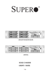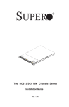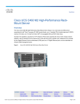
1
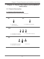
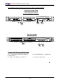
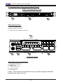
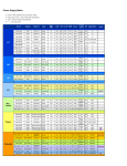
®
SUPER
UPER
R
UPER
R
superserver 5011H
NIC 2
UPERMICR
R
UPERMICR
R
NIC 1
RESET
The SC811 Series
superserver 5011E
NIC 2
The SC811i Series
SC811 CHASSIS
USER'S GUIDE
1.0
RESET
NIC 1
SC811 Chassis User’s Guide
The information in this User’s Guide has been carefully reviewed and is believed to be
accurate. The vendor assumes no responsibility for any inaccuracies that may be
contained in this document, makes no commitment to update or to keep current the
information in this manual, or to notify any person or organization of the updates. Please
Note: For the most up-to-date version of this manual, please see our
web site at www.supermicro.com.
SUPERMICRO COMPUTER reserves the right to make changes to the product described in
this manual at any time and without notice. This product, including software, if any, and
documentation may not, in whole or in part, be copied, photocopied, reproduced, translated
or reduced to any medium or machine without prior written consent.
IN NO EVENT WILL SUPERMICRO COMPUTER BE LIABLE FOR DIRECT, INDIRECT,
SPECIAL, INCIDENTAL, OR CONSEQUENTIAL DAMAGES ARISING FROM THE USE OR
INABILITY TO USE THIS PRODUCT OR DOCUMENTATION, EVEN IF ADVISED OF THE
POSSIBILITY OF SUCH DAMAGES. IN PARTICULAR, THE VENDOR SHALL NOT HAVE
LIABILITY FOR ANY HARDWARE, SOFTWARE, OR DATA STORED OR USED WITH THE
PRODUCT, INCLUDING THE COSTS OF REPAIRING, REPLACING, INTEGRATING,
INSTALLING OR RECOVERING SUCH HARDWARE, SOFTWARE, OR DATA.
Any disputes arising between manufacturer and customer shall be governed by the laws of
Santa Clara County in the State of California, USA. The State of California, County of
Santa Clara shall be the exclusive venue for the resolution of any such disputes.
Supermicro's total liability for all claims will not exceed the price paid for the hardware
product.
Unless you request and receive written permission from SUPER MICRO COMPUTER, you
may not copy any part of this document.
Information in this document is subject to change without notice. Other products and
companies referred to herein are trademarks or registered trademarks of their respective
companies or mark holders.
Copyright © 2004 by SUPER MICRO COMPUTER INC.
All rights reserved.
Printed in the United States of America
1-2
Chapter 1: Safety Information and Technical Specifications
Table of Contents
Chapter I: Safety Information and Technical Specifications .......... 1-4
1-1. Electrical Safety Guidelines ............................................................. 1-4
1-2. General Safety Guidelines ............................................................... 1-5
1-3. ESD Safety Guidelines ....................................................................... 1-6
1-4. Operation Safety Guidelines .......................................................... 1-6
1-5. Product Compliance Information ................................................. 1-8
1-6. Packing List and
the SC811 Specifications ............................ 1-9
Chapter 2: Chassis Description and Installation Procedures ........ 2-1
2-1. Chassis Description ........................................................................... 2-1
A. Contents of the Accessory Kit ............................................................... 2-1
B. Chassis Front View and the Front Control Panel ................................ 2-2
C. Chassis Rear View and the Back Panel .............................................. 2-4
2-2. Chassis Installation ........................................................................... 2-5
A. Important Safety Guidelines ..................................................................... 2-5
B. Tools Needed .............................................................................................. 2-5
C-1. Accessing the SCA Drive Tray and Installing a SCSI Drive .......... 2-6
C-2. Accessing the IDE Drive Tray and Installing a HDD ........................ 2-7
D. Removing the Top Cover of the Chassis ............................................... 2-8
E. Accessing the Front Chassis Fans ........................................................ 2-9
F. Accessing the Power Supply ................................................................ 2-10
G. Installing the Motherboard ...................................................................... 2-12
H. Installing Chassis Rails ........................................................................... 2-14
I. Rack Installation ........................................................................................ 2-16
1-3
SC811 Chassis User’s Guide
Chapter 1-Safety Information and Technical
Specifications
1-1 Electrical Safety Guidelines
Warning: To avoid electrical shock,
cords as follows:
check the power
Checking the Power Cords
!Use the exact type of power cords as required.
!Be sure to use power cord(s) that came with safety certifications.
!The power cord(s) must be compliant with the AC voltage requirements in your
region.
!The power cord plug cap must have an electrical current rating that is at least
125% of the electrical current rating of this product.
!The power cord plug cap that plugs into the AC receptacle on the power
supply must be an IEC 320, sheet C13, type female connector.
!Be sure to disconnect the power supply before accessing the SC811 or its
components.
!Plug the Power cord(s) into a socket that is properly grounded before
turning on the power.
Warning: Follow the guidelines below to avoid possible
damages to the system or injury to yourself:
General Electrical Safety Guidelines
! Be aware of the locations of the power switches on the chassis and in the
room, so you can disconnect the power supply if an accident occurs.
! Take extra precautionary measures when working with high voltage
components. It is not recommended to work alone.
! Before removing or installing main system components, be sue to disconnect
the power first. Turn off the system before you disconnect the PS.
Use only one hand when working with powered-on electrical equipment to
avoid possible electrical shock.
1-4
Chapter 1: Safety Information and Technical Specifications
Use rubber mats specifically designed as electrical insulators when working
with computer systems.
The power supply or power cord must include a grounding plug and must
be plugged into grounded outlets.
Motherboard Battery: CAUTION -Make sure not to install the onboard battery
upside down to avoid possible explosion. Make sure that the positive side
should be facing up on the motherboard. This battery must be replaced
only with the same or an equivalent type recommended by the manufacturer. Dispose of used batteries according to the manufacturer's instructions.
CD-ROM Laser: CAUTION - Do not open the enclosures of power supplies
or CD ROM to avoid injury.
1-2 General Safety Guidelines
Warning: Follow these rules to ensure general safety:
Keep the area around the SC811 clean and free of clutter.
To avoid injuries to the back, be sure to use your leg muscles, keep your
back straight, and bend your knees, when lifting the system.
After removing the components or chassis covers from the system, place
them on a table for safeguard.
Avoid wearing loose clothing to preventing it from coming into contact with
Be sure to remove any jewelry or metal objects before working on the
chassis to avoid short circuits should these objects come into contact
with power circuits.
After accessing the interior of the chassis, be sure to close the chassis
with chassis covers and secure the chassis to the racks with screws.
1-5
SC811 Chassis User’s Guide
1-3 ESD Safety Guidelines
Electric Static Discharge (ESD) can damage electronic components. To prevent damage to your system board, it is
important to handle it very carefully. The following measures are
generally sufficient to protect your equipment from ESD.
Use a grounded wrist strap designed to prevent static discharge.
Keep all components and printed circuit boards (PCBs) in their antistatic
bags until ready for use.
Touch a grounded metal object before removing the board from the antistatic bag.
Do not let components or PCBs come into contact with your clothing, which may
retain a charge even if you are wearing a wrist strap.
Touch a grounded metal object before removing the board from the antistatic
bag.
Handle a board by its edges only; do not touch its components, peripheral
chips, memory modules or contacts.
When handling chips or modules, avoid touching their pins.
Put the motherboard and peripherals back into their antistatic bags when not in
use.
For grounding purposes, make sure your computer chassis provides excel
lent conductivity between the power supply, the case, the mounting
fasteners and the motherboard.
1-4 Operation Safety Guidelines
Warning: For proper cooling, make sure to install all
chassis covers before turning on the system. If this rule is
not strictly followed, warranty may become void. Do not open
the casing of a power supply. Power supplies can only be
accessed and serviced by a qualified technician of the manufacturer.
1-6
Chapter 1: Safety Information and Technical Specifications
To avoid personal injury and property damage, please carefully
follow all the safety steps listed below:
Before accessing the chassis:
1. Turn off all peripheral devices connected to the SC811.
2. Press the power button to power off the system.
3. Unplug all power cords from the system or the wall outlets.
4. Disconnect all the cables and label the cables for easy identification.
5. Use a grounded wrist strap designed to prevent static discharge when
handling components.
Removing the chassis covers:
After completing the above steps, you can remove the covers and install
components/peripheral devices into the chassis as described in Chapter 2.
1. Unlock and remove the screws and fasteners to remove the cover or
components.
2. Save all the screws and fasteners for later use. (If necessary, label these
screws or fasteners for easy identification.)
3. Follow the instruction given in Chapter 3 to remove the chassis covers.
Reinstalling the chassis covers:
To maintain proper system cooling and airflow, do not operate the system
without installing all chassis covers back to the chassis. To reinstall the chassis
covers, please follow the steps listed below:
1. Make sure that all components and devices are securely fastened
on the chassis and there are no loose parts/screws inside the chassis.
2. Make sure that all cables are properly connected to the connectors and ports.
3. Use the original screws or fasteners to install the covers to the chassis.
4. Be sure to lock to the chassis or the system to prevent unauthorized access.
5. For proper cooling, enclose the chassis with covers before operating the
system.
1-7
SC811 Chassis User’s Guide
Before installing the chassis into a rack:
1. Make sure that the rack is securely anchored onto a unmovable surface or
structure before installing the chassis into the rack.
2. Unplug the power cord(s) of the rack before installing the chassis into the
rack.
3. Make sure that the system is adequately supported. Make sure that all the
components are securely fastened to the chassis toprevent components falling off from the chassis.
4. Be sure to install an AC Power Disconnect for the entire rack assembly and
this Power Disconnect must be clearly marked.
5. The rack assembly shall be properly grounded to avoid electric shock.
6. The rack assembly must provide sufficient airflow to the chassis for proper
cooling.
1-5 Product Compliance Information
If integrated with a motherboard validated and recommended by
Supermicro, and configured based upon the instructions outlined in this
manual, the SC811 Chassis is compliant with the following safety
standards/requirements:
Product Safety
*Canada/USA--UL60 950-CSA60 950
*European Union--EN 60 950
*International--IEC 60 950
Electromagnetic Compatibility (EMC)-Emissions
*European Union--EN55022: 1994
*International--CISPR 22
*USA--Title 47 CFR, Part 15
Electromagnetic Compatibility-Immunity
*European Union--EN55024: 1998
*International--CISPR 24
Power Line Harmonics/Voltage Flicker
*European Union--EN61000-3-2/EN61000-3-3
*International--IEC61000-3-2
1-8
Chapter 1: Safety Information and Technical Specifications
1-6 Packing List and the SC811 Specifications
A. The SC811 chassis contains the following:
The SC 811i (811-IDE) Series:
!#'())$
!#'())$
!#'())$
&!#'())$
*
+,-#(./
0'
1.
%
!
! !&&
! !" !#$
!#$
&!#$
The SC 811T (811-Serial ATA) Series:
!#'())$
!#'())$
!#'())$
&!#'())$
)#.
+,)
$
2$
2$
3
2$
*
+,-#(./
0'
1.
%
!
! !&&
! 3&&
3
3 !" !#$
!#$
&!#$
!" !#$
!"&!#$
%
! !&&
! &
34
3
!#$
!#$
&!#$
!#$
!"&!#$
The SC 811S (811-SCSI) Series:
!#'())$
!#'())$
&!#'())$
)#.
+,)
$
2$
2$
*
+,-#(./
0'
1.
1-9
SC811 Chassis User’s Guide
B. The Accessory Kit contains the following:
#'#0
+'1
*
+,-#(.K.
1.
C. The Power Supply Specifications of the SC811
Power supply spec
Mfr. Model#
Mfr. Part#
Rated AC input voltage
Rated input frequency
Rated input current
Rated output power
Maximum rated BTU
Nominal DC output
+3.3V
+5V
+12V
-12V
+5Vsb
250W
EFA-250
PWS-021
100-240V AC
50-60 Hz
4A MAX
250W
1320 BTUs/Hr
260W
SP262-1S
PWS-0055
100-240V AC
50-60 Hz
5A MAX
260W
1370 BTUs/Hr
350W
FSP350-601U
PWS-042-24
100-240V AC
50-60 Hz
6A MAX
350W
1850 BTUs/Hr
420W
SP423-1S
PWS-0053
100-240V AC
50-60 Hz
7A MAX
420W
2220 BTUs/Hr
20A
25A
13A
0.8A
2A
15A
25A
18A
1A
2A
20A
25A
25A
0.8A
2A
20A
30A
32A
1A
2A
1-10
Chapter 1: Safety Information and Technical Specifications
D. The Serial ATA Back Panel (*SC811T Only)
D-1 Jumper Settings and Pin Definitions
L(-)
L
L L
O
($...Q
)
)
#.1
(YY*1.
Z
.-)
.( #--#+..
0+.[\+.[
D-2 Jumper Setting Locations
JP18 JP25
OH/DRIVE FAIL
+
GEM424 RST
+
1
+
+12V
+
IPMB
+
2
I C
JP27:COM_ACT1
JP29: COM_ACT2
JP32: ACT_OUT
+
GND
+
+
GND
+
+
JP25:OH TEMP.
OPEN 45 C
1-2
50 C
2-3
55 C
1#
+
+5V
#1
ATA-S
S UPER
JP18:BUZZER RESET
+
+
+
1LIAF
1TCA
0TCA
#0
GND
ACT0
GLOBAL ACT
JP34: GEM424
+
ACT1
R
SATA810
REV 1.00
COM_ACT
ACT IN
JP26
E. The SCSI Back Panel (*SC811S Only)
E-1 Jumper Settings and Pin Definitions
L(-) O
($...Q #.
L&
)
$
.
.
E-2 Jumper Setting Locations
JP14
36
+12V
A
1
+
JP9
JP10
S UPER
+
GND
R
SCAR1US
LVD1
1
REV 1.1
+
+
+5V
JP14
+
+
1
JP14: DELAY START
1-11
2
IC
U11
GND
68
+
SC811 Chassis User’s Guide
Notes
1-12
Chapter 2: Chassis Description and Installation Instructions
Chapter 2: Chassis Description and Installation
Instructions
2-1 Chassis Description
A. Contents of the Accessory Kit:
The following items are included in the Accessory Kit:
M/B
HDD
B
A
B. Flat head 6-32 x 5 mm [0.197]
A. Pan head w/ lock
6-32 x 4.5 mm [0.177]
DRIVE
B
D
B. Flat head 6-32 x 5 mm [0.197]
E
E. Round head M3 x 5 mm [0.197]
D. Pan head 6-32 x 5 mm [0.197]
RAIL
G
H
I
I.
G. Round head M4 x 4 mm [0.157]
H. Flat head M5 x 12 mm [0.472]
2-1
Washer for M5
SC811 Chassis User’s Guide
C. Chassis Front View and the Front Control Panel
Chassis Front View
The 811S/SC811T Series
UPER
R
UPER
R
superserver 5011H
NIC 2
UPERMICR
B
A
NIC 1
R
RESET
C
The 811i Series
superserver 5011E
NIC 2
UPERMICR
NIC 1
R
RESET
A1
B
C
Front Panel I/O Device Definitions
A. 1" Hot-swap SCA Drive Bay(2)
(*SC811S/T)
B. Slim CDROM(1) (*Optional)
A1. IDE Drive Bay(2) (*SC811i)
C. Floppy (*Optional)
NIC 2
NIC 1
RESET
2-2
Chapter 2: Chassis Description and Installation Instructions
Front Panel LED Indicators
J
I
H
F
G
E
D
LED Button Definitions
H. LAN1
D. Power Button
E. Reset Button
I. LAN2
J. Overheat
F. Power Indicator
G. HDD Activity
(*Note: After the Alarm goes off, please press the Reset Button to
reactivate the function.)
Front Control Panel LED Button Descriptions
"#$%
)
&
]
*$$
-2
"+,"+ ]
-./
*0
'
OO
$,
OO
$,
OO
OO
2-3
$(
1.-
1.-OO
/+..
#+..
3,0
3+..
1+#+.0
1.-Z
.
1.-#-
$
SC811 Chassis User’s Guide
D. Chassis Rear View and the Back Panel
SC811 Chassis Rear View
A
B
C
Back Panel Devices
A. Power Supply Module
B. Back Panel I/O Ports
C. Full size PCI Expansion Slot (1)
H
D
E
F
G
*I/O Back Panel
Back Panel I/O Port Definitions
D. Keyboard & Mouse
E. USB Ports
F. COM/Video Ports
G. LAN1 & LAN2
H. Parallel Port
(*Note: The actual I/O Configuration of your system might be different
from the one shown above.)
2-4
Chapter 2: Chassis Description and Installation Instructions
2-2 Chassis Installation
A. Important Safety Guidelines
Stop
This product shall only be accessed, assembled and serviced
by technically qualified personnel or technicians.
To avoid personal injury and property damage, please read all the information
provided in Chapter 1, and carefully follow all the Safety Guidelines listed before
accessing or servicing the SC811 or its components. For your convenience, some
Safety Steps are also listed below:
Safety Steps
Before accessing the chassis:
1. Turn off all peripheral devices and turn off the power supply connected to the
SC811.
2. Unplug all power cords from the system or the wall outlets.
3. Disconnect all the cables and label the cables for easy identification.
4. Use a grounded wrist strap designed to prevent static discharge when handling components.
Removing the chassis covers:
After completing the above steps, you can remove the chassis covers and install
components and devices into the chassis as described in this chapter.
1. Unlock and remove the screws and fasteners to remove the cover or components.
2. Save all the screws and fasteners for later use. (If necessary, label these screws
or fasteners for easy identification.)
3. Follow the instructions given in this chapter to remove the chassis covers.
B. Tools needed
1. Fillips Screw Driver
2. Antistatic Strap
2-5
SC811 Chassis User’s Guide
C-1. Accessing the SCA Drive Tray and Installing a SCSI
To install a SCA drive into the chassis, you need to first remove the SCA drive
tray from the chassis.
Procedures
1. Press the release tab located on the side of the drive tray door to unlock the
drive tray.
2. Once the drive tray is loosened, pull the drive tray out from the chassis.
2a
2b
1
3. Mount a hard drive in the drive tray, and secure it with 4 screws as
shown below:
3a
B
3b
2-6
Chapter 2: Chassis Description and Installation Instructions
C-2. Accessing the IDE Drive Tray and Installing an IDE HDD
To install an IDE HDD into the chassis, you need to first remove the IDE HDD
drive tray from the chassis.
Procedures
1. Press the release tab located on the top of the drive tray to unlock the drive
tray as shown below.
2. Once the drive tray is loosened, pull the drive tray out from the chassis.
1
2
3. Mount a hard drive in the drive tray, and secure it with 4 screws as
shown below:
3a
3a
3b
3b
B
2-7
SC811 Chassis User’s Guide
D. Removing the Top Cover of the SC811 Chassis
Before installing any components, replacing chassis fans or accessing the
motherboard, you will first need to remove the top cover.
Procedures
1. Press the release tabs to release the cover from its locking position.
1
2
2. Once the top cover is released from its locking position, push the cover toward
the rear side and slide it out from the chassis.
2-8
Chapter 2: Chassis Description and Installation Instructions
E. Accessing the Power Supply
(*Caution: Unplug the Power Cord before removing the Power
Supply!!)
Procedures
1. Remove the two screws from the power supply panel.
1
2 . Once the power supply module is released from its locking position, remove it from the chassis as shown below:
2
!
Warning: Do not open the casing of a power supply.
Power supplies can only be accessed and serviced by a
qualified technician from the manufacturer.
2-9
SC811 Chassis User’s Guide
F. Installing the Motherboard
Be sue to disconnect the power supply before accessing or installing the motherboard into the chassis. However, you will need to, first, identify the CPU locations,
and then, install the correct type of standoffs under the CPUs before installing the
motherboard into the chassis. (Refer to Chapter 1 for Safety Guidelines.)
Procedures
1. Lay the chassis on a flat surface.
2. Remove two screws from the riser card bracket, and, then, remove it from
the chassis for easy motherboard installation.
2a
2b
2-10
Chapter 2: Chassis Description and Installation Instructions
3. Lay the Mylar sheet that came with the chassis package between the
motherboard and the chassis for insulation. Secure the motherboard and the
Mylar sheet to the chassis with Type A screws as shown above. (*Please refer
to Page 2-1 MB kit for the Type A screw.)
3b
A
3a
4. Secure the CPU heatsink mechanism to the motherboard.
(**Note: the CPU and the motherboard shown above are for reference only!!
Both items are not included in the SC811 shipping package.)
!
Warning: For proper cooling, please make sure that all the
chassis covers are installed before you operate the system. Out
of warranty damage can occur if this rule is not strictly followed.
2-11
SC811 Chassis User’s Guide
G. Installing Chassis Rail (-Inner Rails)
Please make sure that the chassis covers and chassis rails are installed on the
chassis before you install the chassis into the rack.
To avoid personal injury and property damage, please carefully
follow all the safety steps listed below:
Before installing the Chassis rails:
1. Enclose the chassis with chassis covers.
2. Unplug the AC power cord(s).
3. Remove all external devices and connectors.
Procedures to Install Chassis Rails
1. Included in the shipping package are a pair of rail assemblies. In each rail
assembly, locate the inner rail and the outer rail.
2. Press the locking tab to release the inner rail from its locking position and
pull out the inner rail from the rail assembly. (*The inner rails are to be attached
to the chassis and the outer rails are to be installed in the rack.)
Outer rail (to be installed in the
rack)
Pull out the Inner
rail (to be
attached on the
chassis)
Press the Locking Tab
2-12
Chapter 2: Chassis Description and Installation Instructions
3. Locate the five holes on each side of the chassis and locate the five corresponding holes on each of the inner rail.
G
4. Attach an inner rail to each side of the chassis and secure the inner rail to
the chassis by inserting five Type G screws through the holes on the chassis
and the inner rail. (Refer to Page 2-1 for the Type G screw.)
5. Repeat the above steps to install other rail on the chassis.
2-13
SC811 Chassis User’s Guide
H-1 Rack Installation for the Traditional IU Design
After you have installed the inner rails on the chassis, you are ready to install the
outer rails of rail assemblies to the rack.
(* The rails are designed to fit in the racks with the depth of 28" to 33".)
Procedures
1. In the package, locate a pair of front (-short) and rear (-long) brackets. Please
note that the brackets are marked with Up/Front Arrows (-front) and Up/Rear
arrows (-rear).
2. Secure the front (-short) bracket (marked with the Up/Front arrows) to the
outer rail with two Type G screws.
3. Attach the rear (-long) bracket to the other end of the outer rail and secure the
rear (long) bracket to the outer rail with a Type G screw as shown below.
4. Measure the depth of your rack and adjust the length of the rails accordingly.
5. Repeat the same steps install the other outer rail on the chassis.
6. Secure both outer rail assemblies to the rack with Type H screws and Type I
washers.
6
H
I
4
3
2
G
2-14
G
Chapter 2: Chassis Description and Installation Instructions
7. Slide the SC811 chassis into the rack as shown below:
(The SC811 may not slide into the rack smoothly or easily when installed the first
time. However, some adjustment to the slide assemblies might be needed for easy
installation.)
8. You will need to release the safety taps on both sides of the chassis in order
to completely remove the chassis out of the rack.
7a
7b
2-15
SC811 Chassis User’s Guide
H-2 Rack Installation for the Open-Rack Design
After you have installed the inner rails on the chassis, you are ready to install the
outer rails of rail assemblies to the rack.
(* The rails are designed to fit in the racks with the depth of 28" to 33".)
Procedures
1. In the package, locate a pair of front (-short) and rear (-long) brackets. Please
note that the brackets are marked with Up/Front Arrows (-front) and Up/Rear
arrows (-rear).
2. Secure the front (-short) bracket (marked with the Up/Front arrows) to the
outer rail with two Type G screws as shown below:
G
2
2-16
Chapter 2: Chassis Description and Installation Instructions
3. Attach the front (-short) bracket to the front end of the rack, and secure it to
the rack with two Type H screws and Type I washers as shown below.
4. Attach the rear (-long) bracket to the rear end of the rack, and secure it to
the rack with two Type H screws and Type I washers as shown below. Repeat
the same steps to install the other outer rail to the other side of rack.
4
H
3
I
H
2-17
I
SC811 Chassis User’s Guide
5. Measure the depth of your rack and adjust the length of the rails accordingly.
Then, secure the rails to the chassis with Type G screws.
6. Slide the inner rails which are attached to the chassis to into the outer rails on
the rack.
5
6
2-18
G