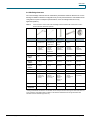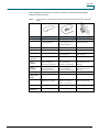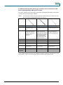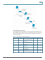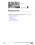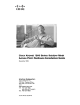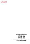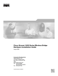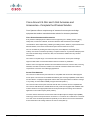
1
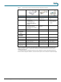
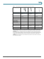
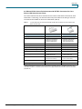
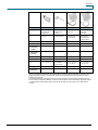
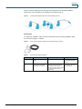
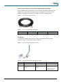
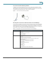
Data Sheet
Cisco Aironet 2.4 GHz and 5 GHz Antennas and
Accessories—Complete the Wireless Solution
®
Cisco Systems offers a complete range of antennas for access point and bridge
equipment that enable a customized wireless solution for almost any installation.
Cisco Aironet Antennas and Accessories
Every wireless LAN deployment is different. When engineering an in-building solution, varying
facility sizes, construction materials, and interior divisions raise transmission and multipath
considerations. When implementing a building-to-building solution, distance, physical obstructions
between facilities, and number of transmission points must be taken into account.
Cisco is committed to providing the best access points, client adapters, and bridges in the
industry—and is also committed to providing a complete solution for any wireless LAN deployment.
Cisco has the widest range of antennas, cable, and accessories available from any wireless
manufacturer.
Cisco offers a complete range of 2.4 GHz and 5 GHz antennas for access point and bridge
equipment that enable a customized wireless solution for almost any installation.
With the Cisco FCC-approved directional and omnidirectional antennas, low-loss cable, mounting
hardware, and other accessories, installers can customize a wireless solution that meets the
requirements of even the most challenging applications.
Access Point Antennas
Cisco Aironet 2.4-GHz access point antennas are compatible with all Cisco RP-TNC-equipped
access points. The antennas are available with different gain and range capabilities, beam widths,
and form factors. Coupling the appropriate antenna and access point allows for efficient coverage
in any facility, as well as better reliability at higher data rates (Table 1).
Cisco Aironet 5 GHz access point antennas have RP-TNC connectors and are compatible with
Cisco Aironet 1200 Series and 1230AG Series access points when equipped with a RM22A radio
module. Selection of the appropriate antenna should provide optimal coverage for the desired
application in the 5 GHz frequency band (Table 2).
The Cisco Aironet 1250 Series Access Points feature multiple-input and multiple-output (MIMO)
technology. These access points have 6 connectors or 3 connectors for 2.4 GHz and 3 connectors
for 5 GHz. Cisco has developed antennas specifically for use with the Cisco Aironet 1250 Series
Access Points but most existing antennas can also be used (Table 3).
All contents are Copyright © 1992–2007 Cisco Systems, Inc. All rights reserved. This document is Cisco Public Information.
Page 1 of 16
Data Sheet
Table 1.
Cisco Aironet 2.4 GHz Access Point Antennas with RP-TNC Connectors
Feature
AIR-ANT5959
AIR-ANT3213
AIR-ANT2410Y-R
Description
Diversity omnidirectional
ceiling mount
Pillar mount diversity
omnidirectional
Yagi mast or wall
mount
Application
Indoor unobtrusive antenna, best
for ceiling mount;
excellent throughput and
coverage solution in high
multipath cells and dense user
population
Indoor, unobtrusive
midrange antenna
Indoor/outdoor
directional antenna for
use with access points
or bridges
Gain
Two separate 2-dBi
omnidirectional elements;
minimum gain of 2.0, maximum
gain of 2.35
5.2 dBi with two radiating
elements
10 dBi
Frequency
2.4 GHz
2.4 GHz
2.4 GHz
Approximate
Indoor Range
at 6 Mbps*
295 ft (90 m)
379 ft (121 m)
548 ft (167 m)
Approximate
Indoor Range
at 54 Mbps*
88 ft (27 m)
114 ft (35 m)
165 ft (50 m)
Beam Width
360°H, 80°V
Cable Length
3 ft (0.91 m)**
3 ft (0.91 m)
3 ft (0.91 m)
Dimensions
5.3 x 2.8 x 0.9 in.
(13.5 x 7.1 x 2.3 cm)
14 x 5 x 1 in.
(35.5 x 12.7 x 2.5 cm)
7.25 x 3 in.
(18.4 x 7.62 cm)
Weight
7 oz (0.19 kg)
Operating
Temperature
0° to +55°C
360°H, 25°V
1 lb (0.45 kg)
0° to +70°C
55°H, 47°V
8 oz (0.23 kg)
–30° to +70°C
* All range estimations are based on an external antenna associating with an integrated Intel Centrino client
adapter under ideal conditions. The distances referenced here are approximations and should be used for
estimation purposes only.
** The cable provided on noted antennas meets UL 2043 certification for plenum rating requirements set by
local fire codes and supports installation in environmental air spaces such as areas above suspended ceilings.
All contents are Copyright © 1992–2007 Cisco Systems, Inc. All rights reserved. This document is Cisco Public Information.
Page 2 of 16
Data Sheet
Feature
AIR-ANT1728
AIR-ANT4941
AIR-ANT2422DG-R**
AIR-ANT2422DW-R
Description
Omnidirectional
ceiling mount
2.2-dBi black
dipole antenna
2.2 dBi gray nonarticulating dipole
antenna
2.2-dBi white dipole
antenna
Application
Indoor midrange
antenna, typically
hung from crossbars
of drop ceilings
Indoor
omnidirectional
coverage
Indoor omnidirectional
coverage
Indoor
omnidirectional
coverage
Gain
5.2 dBi
2.2 dBi
2.2 dBi
2.2 dBi
Frequency
2.4 GHz
2.4 GHz
2.4 GHz
2.4 GHz
Approximate
Indoor Range
at 6 Mbps*
379 ft (116 m)
300 ft (91 m)
300 ft (91 m)
300 ft (91 m)
Approximate
Indoor Range
at 54 Mbps*
114 ft (35 m)
90 ft (27 m)
90 ft (27 m)
90 ft (27 m)
Beam Width
360°H, 36°V
Cable Length
3 ft (0.91 m)
None
None
None
Dimensions
Length: 11.25 in.
(28.5 cm)
5.5 in. (14 cm)
3.9 in (9.9 cm)
5.5 in. (14 cm)
1.1 oz (31 g)
1.1 oz (31 g)
1.1 oz (31 g)
360°H, 65°V
360°H, 65°V
360°H, 65°V
Diameter: 1 in.
(2.5 cm)
Weight
4.6 oz (0.13 kg)
Operating
Temperature
0° to +55°C
0° to +55°C
0° to +55°C
0° to +55°C
* All range estimations are based on an external antenna associating with an integrated Intel Centrino client
adapter under ideal conditions. The distances referenced here are approximations and should be used for
estimation purposes only.
** Best suited for use on the Cisco Aironet 1250 Series Access Point but can also be used on other access
points with RP-TNC connectors.
All contents are Copyright © 1992–2007 Cisco Systems, Inc. All rights reserved. This document is Cisco Public Information.
Page 3 of 16
Data Sheet
Feature
AIR-ANT2485P-R
AIR-ANT2460P-R
AIR-ANT2465P-R
Description
Patch wall mount
Patch wall mount
Diversity patch wall
mount
Application
Indoor/outdoor, unobtrusive,
long-range antenna (may
also be used as a midrange
bridge antenna)
Indoor/outdoor, unobtrusive,
midrange antenna (may
also be used as a midrange
bridge antenna)
Indoor/outdoor,
unobtrusive midrange
antenna
Gain
8.5 dBi
6 dBi
6.5 dBi with two radiating
elements
Frequency
2.4 GHz
2.4 GHz
2.4 GHz
Approximate Indoor
Range at 6 Mbps*
507 ft (155 m)
403 ft (123 m)
418 ft (127 m)
Approximate Indoor
Range at 54 Mbps*
153 ft (47 m)
121 ft (37 m)
126 ft (38 m)
Beam Width
66°H, 56°V
Cable Length
3 ft (0.91 m)
3 ft (0.91 m)
3 ft (0.91 m)**
Dimensions
5.3 x 5.3 x .90 in.
(13.5 x 13.5 x 2.28 cm)
4.1 x 3.9 x .75 in. (10.4 x 9.9
x 1.9 cm)
5 x 6.7 x .90 in. (12.7 x 17
x 2.28 cm)
Weight
8.2 oz (0.23 kg)
6 oz (0.17 kg)
11.6 oz (0.33 kg)
Operating
Temperature
–30° to +70°C
75°H, 73°V
–30° to +70°C
All contents are Copyright © 1992–2007 Cisco Systems, Inc. All rights reserved. This document is Cisco Public Information.
75°H, 57°V
–30° to +70°C
Page 4 of 16
Data Sheet
Table 2.
Cisco Aironet 5 GHz Access Point Antennas with RP-TNC Connectors
Feature
AIR-ANT5135D-R
AIR-ANT5135DG-R****
AIR-ANT5135DW-R
Description
3.5-dBi black dipole
antenna
3.5 dB5 gray nonarticulating dipole
antenna
3.5-dBi white dipole
antenna
Application
Indoor omnidirectional
coverage
Indoor omnidirectional
Indoor omnidirectional
coverage
Gain
3.5 dBi
3.5 dBi
3.5 dBi
Frequency***
5 GHz
5 GHz
5 GHz
Approximate Indoor
Range at 6 Mbps*
675 ft (206 m)
675 ft (206 m)
675 ft (206 m)
Approximate Indoor
Range at 54 Mbps*
75 ft (21 m)
75 ft (21 m)
75 ft (21 m)
Beam Width
360°H, 40°E
Cable Length
None
None
None
Dimensions
5.3 x 0.6 in.
3.61 x .06 in
5.3 x 0.6 in.
(13.5 x 1.5 cm)
(9.2 x 1.5 cm)
(13.5 x 1.5 cm)
Weight
1 oz (28.3 g)
1 oz (28.3 g)
1 oz (28.3 g)
Operating Temperature
0° to +55°C
360°H, 40°E
0° to +55°C
360°H, 40°E
0° to +55°C
* All range estimations are based on an external antenna associating with an integrated Intel Centrino client
under ideal conditions. The distances referenced here are approximations and should be used for estimation
purposes only.
** The cable provided on noted antennas meets UL 2043 certification for plenum rating requirements set by
local fire codes and supports installation in environmental air spaces such as areas above suspended ceilings.
*** 5 GHz antennas are denoted by either a blue dot on the radome or blue marker on the cable near the
connector.
**** Best suited for use on the Cisco Aironet 1250 Series Access Point but can also be used on other access
points with RP-TNC connectors.
All contents are Copyright © 1992–2007 Cisco Systems, Inc. All rights reserved. This document is Cisco Public Information.
Page 5 of 16
Data Sheet
2.4 GHz and 5 GHz Access Point Antennas with RP-TNC Connectors for Cisco
Aironet 1250 Series Access Points
Cisco offers antennas that can be used with the Cisco Aironet 1250 Series Access Points, which
feature 802.11n technology. The antennas and access points utilize an RP-TNC type connector.
Two antennas are available for the 2.4 and 5 GHz band. (Table 3).
Table 3.
2.4 GHz And 5 GHz Access Point Antennas with RP-TNC Connectors for Cisco Aironet 1250
Series Access Points
Feature
AIR-ANT2430V-R
AIR-ANT5140V-R
Description
Ceiling mount omnidirectional
Ceiling mount omnidirectional
Application
Indoor carpeted area type,
unobtrusive omnidirectional
antennas for Cisco Aironet
1250 Series MIMO Radios
Indoor carpeted area type
unobtrusive omnidirectional
antenna for Cisco Aironet
1250 Series MIMO Radios
Gain
3.0 dBi
4.0 dBi
Frequency
2.4 GHz
5 GHz
Approximate Indoor Range at 6 Mbps*
507 ft (155 m)
403 ft (123 m)
Approximate Indoor Range at 54 Mbps*
153 ft (47 m)
121 ft (37 m)
Beam Width
360°H, 60°V
Cable Length
3 ft (0.91 m)
3 ft (0.91 m)
3 cables with RP-TNC
3 cables with RP-TNC
12.1 x 4.2 x 1.6 in.
6.9 x 3 x .9 in
Dimensions
360°H, 45°V
(30.73 x 10.67 x 4.06 cm)
(17.53 x 7.62 x 2.29 cm)
Weight
27 oz (0.76 kg)
14.1 oz (0.40 kg)
Operating Temperature
0º to +55ºC
–0º to +55ºC
* All range estimations are based on an external antenna associating with an integrated Intel Centrino client
under ideal conditions. The distances referenced here are approximations and should be used for estimation
purposes only.
All contents are Copyright © 1992–2007 Cisco Systems, Inc. All rights reserved. This document is Cisco Public Information.
Page 6 of 16
Data Sheet
Feature
AIR-ANT5145V-R
AIR-ANT5160V-R
AIR-ANT5170P-R
AIR-ANT5195P-R
Description
4.5-dBi diversity
omnidirectional
ceiling mount
6 dBi
omnidirectional
antenna
Diversity patch
wall mount
Patch wall or
articulating
mast mount
Application
Indoor midrange
antenna
Indoor/outdoor
midrange antenna
Indoor/outdoor
directional wall
mount antenna
Indoor/outdoor
patch antenna
provides different
mounting options
Gain
4.5 dBi
6 dBi
7.0 dBi
9.5 dBi
Frequency***
5 GHz
5 GHz
5 GHz
5 GHz
Approximate
Indoor Range
at 6 Mbps*
732 ft (223 m)
822 ft (251 m)
880 ft (270 m)
1030 ft (313 m)
Approximate
Indoor Range
at 54 Mbps*
82 ft (25 m)
92 ft (28 m)
140 ft (43 m)
170 ft (52 m)
Beam Width
360°H, 50°E
Cable Length
3 ft (0.91 m)
3 ft (0.91 m)
3 ft (0.91 m)
3 ft (0.91 m)
Dimensions
6.75 x 4.1 in.
(17.1 x 10.4 cm)
12 in. length;
1 in. diameter
5.7 in. (14.5 cm) x
4.3 in. (10.9 cm) x
0.7 in. (1.8 cm)
5.1 in. (12.9 cm) x
5.1 in. (12.9 cm) x
1.0 in. (2.5 cm)
360°H, 17°E
70° H, 50° V
(30.5 x 2.5 cm)
Weight
11.5 oz (0.33 kg)
Operating
Temperature
0° to +55°C
5.3 oz (0.15 kg)
–30° to +70°C
8 oz (0.2 kg)
–30° to +70°C
50° H, 43° V
9 oz. (0.25 kg)
–30° to +70
°C
* All range estimations are based on an external antenna associating with an integrated Intel Centrino client
adapter under ideal conditions. The distances referenced here are approximations and should be used for
estimation purposes only.
** The cable provided on noted antennas meets UL 2043 certification for plenum rating requirements set by
local fire codes and supports installation in environmental air spaces such as areas above suspended ceilings.
*** 5 GHz antennas are denoted by either a blue dot on the radome or blue marker on the cable near the
connector.
All contents are Copyright © 1992–2007 Cisco Systems, Inc. All rights reserved. This document is Cisco Public Information.
Page 7 of 16
Data Sheet
2.4 GHz Bridge Antennas
Cisco Aironet bridge antennas allow for extraordinary transmission distances between two or more
buildings. Available in directional configurations for point-to-point transmission and omnidirectional
configuration for point-to-multipoint implementations, Cisco has a bridge antenna for every
application (Table 4).
Table 4.
Cisco Aironet 2.4 GHz Access Point and Bridge Antennas with RP-TNC Connectors for Cisco
Aironet 1200 and 1300 Series products
AIR-ANT2506
AIRANT24120
AIRANT2414S-R
AIR-ANT1949
AIR-ANT3338
Description
Omnidirection
al mast mount
High-gain
omnidirectiona
l mast mount
Vertically
polarized
sector
Yagi mast
mount
Solid dish
Application
Outdoor shortrange point-tomultipoint
applications
Outdoor
midrange
point-tomultipoint
applications
Outdoor long
range point-tomultipoint
applications
Outdoor
midrange
directional
connections
Outdoor longrange
directional
connections
Gain
5.2 dBi
12 dBi
14 dBi
13.5 dBi
21 dBi
Approximate
Range at
2 Mbps*
3.3 miles (5.31
km)
15.81 miles
(25.43 km)
16.71 miles
(26.89 km)
18.33 miles
(29.49 km)
26.49 miles
(42.62 km)
Approximate
Range at
11 Mbps*
1.66 miles
(2.66 km)
7.92 miles
(12.75 km)
8.89 miles
(14.30 km)
11.19 miles
(18.01 km)
20.1 miles
(32.33 km)
Approximate
Range at
54 Mbps*
.21 miles
(.34 km)
1.0 miles
(1.6 km)
1.26 miles
(2.02 km)
1.41 miles
(2.27 km)
4.46 miles
(7.17 km)
Beam Width
360°H, 36°V
Cable Length
3 ft (0.91 m)
1 ft (0.30 m)
5 ft (1.5m)
3 ft (0.91 m)
2 ft (0.61 m)
Dimensions
Length: 11.5
in. (29.2 cm)
Length: 42 in.
(107 cm)
Length: 36 in.
(91 cm)
Length: 18 in.
(46 cm)
Diameter 24
in. (61 cm)
Diameter: 1 in.
(2.5 cm)
Diameter: 1.25
in. (3.1 cm)
Width: 6 in.
(15 cm)
Diameter: 3 in.
(7.6 cm)
360°H, 7°V
90°H, 8.5°V
30°H, 25°V
12
°H, 12°V
Depth: 4 in.
(10 cm)
Weight
5 oz (0.14 kg)
1.5 lb (0.68
kg)
Operating
Temperature
–30° to +70°C
–30° to +70°C
6.5 lb (3 kg)
–30° to +70°C
12 oz (34 kg)
–30° to +
70°C
11 lb (5 kg)
–30° to +70°C
* All range estimations are based on use of a BR 1310 access point and the same type of antenna at each end
of the connection under ideal outdoor conditions. The distances referenced here are approximations and
should be used for estimation purposes only.
All contents are Copyright © 1992–2007 Cisco Systems, Inc. All rights reserved. This document is Cisco Public Information.
Page 8 of 16
Data Sheet
Table 5 highlights the antennas for use with the Cisco Aironet 1400 Series Wireless Bridge
featuring an N-type connector.
Table 5.
Cisco Aironet 5.8 GHz Bridge Antennas with N-Type Connectors for Cisco Aironet 1400 Series
Bridges
Feature
AIR-ANT58G9VOA-N
AIR-ANT58G10SSA-N
AIR-ANT58G28SDA-N
Description
Omnidirectional mast mount
Sector antenna, mast mount
Dish antenna, mast mount
Application
Outdoor short-range point-tomultipoint applications
Outdoor medium-range
point-to-point and point-tomultipoint applications
Outdoor long-range
directional connections
Gain
9.0 dBi
9.5 dBi
28.0 dBi
Frequency
5.8 GHz
5.8 GHz
5.8 GHz
Polarization
Vertical
Vertical or horizontal
Vertical or horizontal
Field configurable
Field configurable
Elevation
Adjustment
None
None
+/– 12.5 degrees
Approximate
Range
at 9 Mbps*
8 miles (13 km)
8 miles (13 km)
23 miles (37 km)
(with 22.5 dBi captive
antenna on the remote site)
(with 22.5 dBi captive
antenna on the remote site)
(with 28 dBi antennas on
each end)
Approximate
Range
at 54 Mbps
2 miles (3 km)
2 miles (3 km)
12 miles (19 km)
(with 22.5 dBi captive
antenna on the remote site)
(with 22.5 dBi captive
antenna on the remote site)
(with 28 dBi antennas on
each end)
Beam Width
360° H, 6° V
Supplied
Jumper Cable
Length
4.9 ft. (1.5 m)
4.9 ft. (1.5 m)
4.9 ft. (1.5 m)
Dimensions
Length: 20.25 in. (51.4 cm)
Length: 2.5 in. (6.4 cm)
Diameter: 29 in. (74 cm)
Diameter: .64 in. (1.62 cm)
Width: 2.5 in. (6.4 cm)
Depth: 14.5 in. (36.8 cm)
60° H, 60° V
4.75°H, 4.75°V
Depth: 1.75 in. (4.5 cm)
Weight
2.0 lb. (0.9 kg)
Operating
Temperature
–20° to 60°C
1.25 lb. (0.6 kg)
–20° to 60°C
All contents are Copyright © 1992–2007 Cisco Systems, Inc. All rights reserved. This document is Cisco Public Information.
9.5 lb. (4.3 kg)
–30° to 60°C
Page 9 of 16
Data Sheet
2.4 GHz and 5 GHz Antennas with N Type Connectors for the Cisco Aironet 1500
Series Lightweight Outdoor Mesh Access Points
Cisco offers antennas for the Cisco Aironet 1500 Series Lightweight Outdoor Mesh Access Points
in various gains and antenna types. (Table 6).
Table 6.
Cisco Aironet 2.4 GHz and 4.9-5 GHz Access Point Antennas with N-Type Connectors for Cisco
Aironet 1500 Series Lightweight Outdoor Mesh Access Points*
Feature
AIR-ANT2450V-N
AIR-ANT2455V-N
AIR-ANT2480V-N
Description
5 dBi, direct mount
omnidirectional antenna for 2.4
GHz
5.5 dBi, direct mount
omnidirectional antenna for 2.4
GHz
8 dBi direct mount
omnidirectional antenna for 2.4
GHz
Application
Omnidirectional antenna for
outdoor mesh access points.
Suitable for all access point
deployments, specifically for
cable strand mount
applications.
Omnidirectional antenna
suitable for use on Cisco
Aironet 1500 Series Lightweight
Outdoor Mesh Access Points in
all deployments. Not suitable for
use on Cisco Aironet 1500
Series Lightweight Outdoor
Mesh Access Points in cable
strand mount situations.
Extended range omnidirectional
antenna for outdoor mesh
access points. Suitable for pole
or roof mounting deployments.
Gain
5 dBi
5.5 dBi
8 dBi
Frequency
2.4 GHz
2.4 GHz
2.4 GHz
Beam width
30° V
25° V
Cable Length
None
None
None
Dimensions
11 in. x 1 in.
12.5 in. x 1 in.
19.5 in. x 7/8 in. diameter
(27.94 x 2.54 cm)
(31.75 x 2.54 cm)
(49.5 cm x 2.22 cm)
Weight
0.40 lbs. (0.18 kg)
0.31 lbs. (0.14 kg)
0.45 lbs. (0.20 kg)
Operating
Temperature
–30° to +70 C
–30° to 70°C
10° V
–30° to +70° C
* Cisco Aironet 1500 Series Access Points are available in single-band (2.4 GHz) and dual-band (2.4 GHz and
5 GHz) versions. Check your access point for proper antenna selection before placing an order.
All contents are Copyright © 1992–2007 Cisco Systems, Inc. All rights reserved. This document is Cisco Public Information.
Page 10 of 16
Data Sheet
Feature
AIR-ANT5175V-N
AIR-ANT5180V-N
AIR-ANT5114P-N
AIR-ANT5117S-N
Description
7.5 dBi omnidirectional
antenna for 5 GHz
8 dBi direct mount
omnidirectional
antenna for 5 GHz
14 dBi wall/mast
mount articulating
patch antenna for 5
GHz
17 dBi, 90 degree
mast mount sector
antenna for 5 GHz
Application
Omnidirectional
antenna suitable for
use on Cisco Aironet
1500 Series
Lightweight Outdoor
Mesh Access Points in
all deployments.
Omnidirectional
antenna for Cisco
Aironet 1520 series
mesh access points.
Suitable for all
deployments, including
cable strand mount
applications.
Recommended for
medium range point to
point deployments
Recommended for
point-to-multipoint
deployments of
medium to long range.
Gain
5 GHz bands = 7.5 dBi
8 dBi
14 dBi
17 dBi
4.9–5.85 GHz
4.9–5.85 GHz
4.9 GHz bands = 6 dBi
Frequency
4.9–5.8 GHz
4.9–5.85 GHz
Beam width
16°V
16° V
Cable Length
1 ft (0.30 m)
None
1 ft. (0.30 m)
None
Dimensions
11.65 in. x 1 in.
11 in. x 1 in.
(27.94 x 2.54 cm)
4 1/8 in. x 4 1/8 in.
(10.48 cm x 10.48 cm)
24 1/2 in. x 2 ½ in.
(62.23 cm x 6.35 cm)
(29.41 x 2.54 cm)
Weight
0.38 lbs. (0.17 kg)
Operating
Temperature
–30° to 70°C
Figure 1.
0.4 lbs. (0.18 kg)
–30° to +70 C
25° H, 29° E
0.70 lbs. (0.32 kg)
–30° to +70° C
90° H, 8° E
1.95 lbs. (0.88 kg)
–30° to +
70° C
Optional, Higher-Gain Antennas Extend the Range of Access Points
All contents are Copyright © 1992–2007 Cisco Systems, Inc. All rights reserved. This document is Cisco Public Information.
Page 11 of 16
Data Sheet
Low-Loss/Ultra-Low-Loss Cables
Low-loss cables extend the length between any Cisco Aironet 2.4 GHz and 5 GHz radio and the
antenna with RP-TNC connectors. With a loss of 6.7 dB per 100 feet (30 m) for the low-loss cable
and 4.4 dB for the ultra-low-loss cable, this provides installation flexibility without a significant
sacrifice in range (Table 7).
Table 7.
Cisco Aironet Low-Loss Antenna Cable Features
Cisco Part Number
Type of Cable
Description
Loss at 2.4 GHz
Loss at 5.8 GHz
AIR-CAB005LL-N
Interconnect
5-ft low loss cable, one straight N
connector, one 90-degree N connector
0.5 dB
0.8 dB
AIR-CAB005LL-R
Interconnect
5-ft low loss cable, one RP-TNC plug,
one RP-TNC jack
0.5 dB
0.8 dB
AIR-CAB010LL-N
Interconnect
10-ft low loss cable, one straight N
connector, one 90-degree N connector
0.9 dB
1.5 dB
AIR-CAB020LL-R
Interconnect
20-ft low loss cable, one RP-TNC plug,
one RP-TNC jack
1.3 dB
2.5 dB
AIR-CAB050LL-R
Interconnect
50-ft low loss cable, one RP-TNC plug,
one RP-TNC jack
3.4 dB
5.75 dB
AIR-CAB100ULL-R
Interconnect
100-ft ultra low loss cable, one RP-TNC
plug, one RP-TNC jack
4.4 dB
7.25 dB
AIR-CAB150ULL-R
Interconnect
150-ft ultra low loss cable, one RP-TNC
plug, one RP-TNC jack
6.6 dB
11 dB
AIR-ACC2537-060
Bulkhead
Extender
5-ft (60 inches) RG-58 type cable with
one RP-TNC plug and one RP-TNC jack
2 dB
3 dB
All contents are Copyright © 1992–2007 Cisco Systems, Inc. All rights reserved. This document is Cisco Public Information.
Page 12 of 16
Data Sheet
With Cisco Aironet bridge antennas, the right mounting hardware, and qualified installation,
wireless links over great distances and obstacles are possible (Figure 2).
Figure 2.
Crossing Great Distances with Cisco Aironet Bridge Antennas
Accessories
To complete an installation, Cisco provides accessories that offer increased capabilities, safety,
and convenience (Figure 3; Table 8).
Figure 3.
Cisco Aironet Antenna Accessories for use with RP-TNC Connectors
Table 8.
Cisco Aironet Accessory Features
Feature
AIR-ACC2537-060
AIR-ACC245LA-R
AIR-ACC2662
Description
60 in. (152 cm) bulkhead
extender
2.4 GHz and 5 GHz lightning arrestor
Mount to provide articulation
of Yagi and AIR-ANT5195
antennas
Application
Flexible antenna cable that
extends access point cabling,
typically within an enclosure
Adds swiveling capability to
Supports both 2.4 GHz and 5 GHz
mast-mounted Yagi antennas
applications; Helps prevent damage
and AIR-ANT5195
due to lightning-induced surges or
static electricity; helps prevent damage
due to lightning-induced surges or
static electricity
All contents are Copyright © 1992–2007 Cisco Systems, Inc. All rights reserved. This document is Cisco Public Information.
Page 13 of 16
Data Sheet
Power Injector Cables for Cisco Aironet 1400 Series Wireless Bridges
Typical installations will place the outdoor unit on an external mast with the power injector unit
placed indoors. These cables come with a pair of F-type connectors on each end. To allow
flexibility in the distance between the units, a variety of cables are available (Table 9).
Figure 4.
Cisco Aironet Power Injector Cables
Table 9.
Cisco Aironet Power Injector Cable Features
Feature
AIR-CAB020DRG6-F=
AIR-CAB050DRG6-F=
AIR-CAB100DRG6-F
Cable Length
20 ft. (6m)
50 ft. (15m)
100 ft. (30m)
Accessories
To complete an installation, Cisco provides a variety of accessories that offer increased
functionality, safety, and convenience (Figure 5; Table 10).
Figure 5.
Cisco Aironet 1400 Series Bridge Accessories
Table 10.
Cisco Aironet 1400 Series Bridge Accessory Features
Feature
AIR-ACCRWM1400
AIR-ACCBRGB=
AIR-ACCMFM1400=
Description
Roof/Wall mount kit
Grounding block
Multifunction mount
Application
Allows mounting to flat surfaces
Helps prevent damage due to
lightning-induced surges or static
electricity
Allows mounting to poles with a
diameter between 1.5 in. and 2.5
in.
Includes full elevation and azimuth
adjustment
Includes both elevation and
polarization adjustment
All contents are Copyright © 1992–2007 Cisco Systems, Inc. All rights reserved. This document is Cisco Public Information.
Page 14 of 16
Data Sheet
Cisco Aironet 1300 Series Mounting Hardware
In addition to the antennas available from Cisco, the Cisco 1300 Series has different mounting
options (Figure 6). These optional mounting kits are available for mounting to a roof, wall, or pole.
The quick-hang mounting bracket allows a simple one-person installation.
Figure 6.
Cisco Aironet 1300 Series Mounting Hardware
Mounting Kits for Cisco Aironet 1300 Series Outdoor Access Point/Bridges
A roof-mount kit is available for use with Cisco Aironet 1300 Series outdoor access points/bridges
(integrated antenna and connectorized versions). A wall-mount kit is available for use with Cisco
Aironet 1300 Series outdoor access points/bridges with RP-TNC type connectors. The wall-mount
kit is for indoor use only. These kits must be ordered separately (Table 11).
Table 11.
Mounting Kits for Cisco Aironet 1300 Series Outdoor Access Points/Bridges
Product Number
Product Description
AIR-ACCWAMK1300=
Cisco Aironet 1300 Series Wall-Mount Kit for use with AIR-BR1310G-x-K9-R
Kit includes:
● Two 1-ft RG-59 power injector cables
● Wall-mount bracket
● Mounting hardware
AIR-ACCRMK1300=
Cisco Aironet 1300 Series Roof-Mount Kit for use with AIR-BR1310G-x-K9
Kit includes:
● Roof-mount mast (pole and mounting base)
● Multifunction mount (allows mounting to roof-mount mast, or directly to a wall)
● Mounting hardware
● 20-ft dual RG-6 cable assembly with F-Type connectors
● 50-ft dual RG-6 cable assembly with F-Type connectors
● Coaxial sealant
● One Cisco Aironet grounding block
● Grounding lug
● Anticorrosion gel
● U-bolts
● Coaxial sealant
● Optional 100-ft dual RG-6 cable available separately
All contents are Copyright © 1992–2007 Cisco Systems, Inc. All rights reserved. This document is Cisco Public Information.
Page 15 of 16
Data Sheet
Cisco Aironet 1500 Series Accessories
In addition to the antennas offered by Cisco for the 1500 Series, there are various accessories that
are available (Table 12).
Table 12.
Cisco Aironet 1500 Series Accessories
Product Number
Product Description
AIR-ACCPMK1500=
Pole Mount Kit
AIR-PWR-ST-LT-TAP=
Streetlight Power Tap, 105-260 VAC
AIR-PWRINJ1500=
Power Injector, In 100–240VAC, Out 48 VDC
AIR-ETH1500-150=
Outdoor Ethernet Cable, 150 ft.
AIR-LAP1510KITP-A
Pole-Top Kit, 2.4 Omni 5 GHz Omni
AIR-LAP1510KITRO-A
Roof-Top Kit, 2.4 Omni 5GHz Omni
AIR-LAP1510KITRS-A
Roof-Top Kit, 2.4 Omni 5GHz Sector
Printed in USA
All contents are Copyright © 1992–2007 Cisco Systems, Inc. All rights reserved. This document is Cisco Public Information.
C78-335020-09 9/07
Page 16 of 16