1
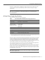
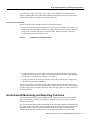
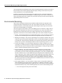
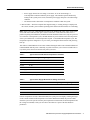
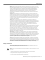
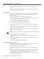
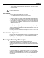
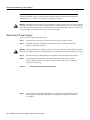
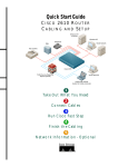
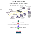
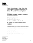
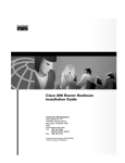
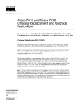
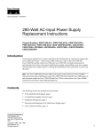
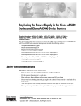
Text Part Number: 78-1900-03
Customer Order Number: DOC-781900=
1200-Watt AC-Input Power Supply
Replacement Instructions
Product Numbers: PWR-7513-AC=, PWR-7513-ACU=, PWR-7513-ACA=,
PWR-7513-ACI=, and PWR-7513-ACE= (Cisco 7513)
PWR-7576-AC=, PWR-7576-ACU=, PWR-7576-ACA=, PWR-7576-ACI=, and
PWR-7576-ACE= (Cisco 7576)
This document contains instructions for installing or replacing a 1200-watt (W), AC-input power
supply in the Cisco 7513 and Cisco 7576 routers.
Note If you are upgrading a Cisco 7513 to a Cisco 7576, use this document as a reference for
transferring power supplies from the Cisco 7513 to the Cisco 7576.
A single power supply is standard equipment in the Cisco 7513. A dual power supply is standard
equipment in the Cisco 7576. A second power supply, when installed, provides redundant power.
In systems with redundant power, the power supplies are load sharing and fully hot swappable. You
can remove and replace one power supply while the remaining supply immediately powers up to
provide full power and to maintain uninterrupted system operation.
Document Contents
This publication contains the following sections:
•
•
•
•
•
•
Product Overview, page 2
Environmental Monitoring and Reporting Functions, page 5
Installation Safety, ESD Precautions, and Tools Required, page 8
Removing and Replacing a Power Supply, page 11
Checking the Installation, page 14
Cisco Connection Online, page 16
Corporate Headquarters
Cisco Systems, Inc.
170 West Tasman Drive
San Jose, CA 95134-1706
USA
Copyright © 1996-1998
Cisco Systems, Inc.
All rights reserved.
1
Product Overview
Product Overview
The AC-input power supply is a modular power supply for the Cisco 7513 and Cisco 7576
multiprotocol, multimedia routers. A second power supply, if installed, provides redundant power.
Power supplies reside in power supply bays (labeled Power A and Power B) in the rear of the router
chassis, as shown in Figure 1.
Note The Cisco 7513 and Cisco 7576 use the same chassis and power supplies. However, the
backplane and the interface processor slot numbering scheme on the card cages are different. The
interface processor slot numbering scheme of the Cisco 7513 is shown in Figure 1. The numbering
scheme has no effect on the location or installation of the power supplies.
Figure 1
Cisco 7513 and Cisco 7576 (Rear-Panel View)
To prevent problems with the Cisco 7513 and Cisco 7576, do not mix DC-input and AC-input
power supplies in the same chassis. Your Cisco 7513 or Cisco 7576 must have either DC-input or AC-input
power supplies.
Caution
2 1200-Watt AC-Input Power Supply Replacement Instructions
AC-Input Power Supply Specifications
Power bay A contains the first (or standard) power supply, and power bay B contains the second
(optional) supply in systems with redundant power. Table 1 lists the AC-input power supply
specifications.
Note The Cisco 7576 features two routers on one backplane. These are identified as router A and
router B. These designations have no relationship to the power bays, which are identified as
power A and power B.
AC-Input Power Supply Specifications
Table 1 lists the AC-input power supply specifications.
Table 1
Cisco 7513 and Cisco 7576 AC-Input Power Supply Specifications
Specification
Rating
AC-input voltage
100 to 240 VAC1, 20 amps maximum
Frequency
50 to 60 Hz
Internal DC voltages
supplied and steady-state
maximum current ratings
+5.2 VAC @ 200A
+12 VAC @ 35A
–12 VAC @ 3A
+24 VAC @ 8A
Input power requirement
1600W
Power output
1200W with a maximum configuration and one or two AC-input power supplies
Heat dissipation
5465 Btu/hr
Weight
25 pounds (11.34 kilograms)
Cable supplied
12 American Wire Gauge (AWG), 20-amp2
1
2
VAC = volts direct current.
The Cisco 7513 and Cisco 7576 require a minimum of 20-amp service with a 20-amp receptacle at the power source. The
power cable supplied with the Cisco 7513 and Cisco 7576 uses a 20-amp male plug.
Dual power supplies are automatically load sharing and redundant, which means that you can install
or replace a second power supply on line. During normal operation, dual power supplies provide
system power simultaneously (load share). When you remove one power supply, the remaining
power supply immediately powers up to provide full power and maintain uninterrupted power to the
system. Whenever possible, connect each power supply to a separate AC source.
The AC-input power supply uses a power factor corrector (PFC) that automatically adjusts for the
input voltage being supplied. The AC-input voltage range is 100 to 240 VAC.
The Cisco 7513 and Cisco 7576 require a minimum of 20-Amp service with a 20-Amp receptacle at
the power source. The power cable supplied with the Cisco 7513 and Cisco 7576 uses a 20-Amp
male plug. Figure 2 shows the cable connector plug and the 20-Amp receptacle required to connect
the 20-amp cable to your AC source.
Note Wiring codes prevent the type of power cables shown in Figure 2 from being used with the
power strips in equipment racks.
1200-Watt AC-Input Power Supply Replacement Instructions
3
Product Overview
Figure 2
20-Amp AC Power Cable Connector and Plug and 20-Amp Receptacle
LED Indications and the Safety Interlock Mechanism
On the Cisco 7513 and Cisco 7576 chassis front panel, the power A and power B LEDs go on when
the power supply in the corresponding bay is installed and supplying power to the system. Both the
power LEDs should be on in systems with redundant power.
LED Indications
The power supply LEDs include the AC OK LED, the FAN OK LED, and the OUTPUT FAIL LED.
(See Figure 3.) The AC OK LED is on when the input power is applied. The FAN OK LED is
normally on; however, it is off if the power supply fan fails. The OUTPUT FAIL LED is normally
off but flashes at power on for a lamp test.
Figure 3
Power Supply LEDs
The OUTPUT FAIL LED lights for either of the following reasons:
•
Power supply DC-output failure, which might be caused by an overload by the system or an
actual failure in the AC-input power
•
Power shutdown that is initiated by the power supply because it detected an out-of-tolerance
voltage condition in the power supply
4 1200-Watt AC-Input Power Supply Replacement Instructions
Environmental Monitoring and Reporting Functions
In systems with a single power supply, and in systems with redundant power when both power
supplies are shutting down, the OUTPUT FAIL LED lights momentarily as the system powers down,
but goes out when the power supply has completely shut down.
Safety Interlock Mechanism
The power supplies feature the following three safety interlock features:
•
An on/off switch with a locking mechanism (see Figure 4) that prevents the power supply from
being removed from the chassis when the power supply switch is in the on (|) position. When the
switch is on, a metal tab extends into a slot in the chassis. When the switch is in the off (O)
position, the tab is raised and clears the slot.
Figure 4
On/Off Switch Locking Mechanism
•
A captive installation screw at the bottom of the power supply front panel provides electrical
grounding and prevents the power supply from vibrating or sliding out of the bay and dislodging
from the power connectors in the backplane. (See Figure 3.)
•
A spring clip on the AC receptacle provides strain relief and prevents the power supply power
cable from being pulled out accidentally.
The power supplies are self-monitoring. Each supply monitors its own temperature and internal
voltages. An internal fan in each power supply draws cooling air from the rear of the chassis, through
the power supply, and out the front of the chassis. The power supply airflow is separate from that of
the rest of the chassis.
Environmental Monitoring and Reporting Functions
The environmental monitoring and reporting functions, controlled by the chassis interface board,
allow you to maintain normal system operation by identifying and resolving adverse conditions
before loss of operation.
The environmental monitoring functions constantly monitor the internal chassis air temperature and
DC supply voltages and currents. Each power supply monitors its own voltage and temperature and
shuts itself down if it detects a critical condition within the power supply. If conditions reach
shutdown thresholds, the system shuts down to avoid equipment damage from excessive heat.
1200-Watt AC-Input Power Supply Replacement Instructions
5
Environmental Monitoring and Reporting Functions
The reporting functions periodically log the values of measured parameters so that you can retrieve
them for analysis later, and the reporting functions display warnings on the console if any of the
monitored parameters exceed defined thresholds.
In addition to monitoring internal temperature and voltage levels, the system also monitors the
blower. If the blower fails, the system displays a warning message on the console. If the blower is
still not operating properly after 2 minutes, the system shuts down to protect the internal components
against damage from excessive heat.
Environmental Monitoring
Three sensors on the Route Switch Processor (RSP2 or RSP4) monitor the temperature of the
cooling air that flows through the processor slots: inlet, hotpoint, and exhaust. The sensors are
located at the bottom, center, and top of the RSP, when facing the interface processor end of the
chassis and viewing the RSP as it is installed.
The power supply uses the Normal, Critical, and Warning levels to monitor DC voltages. Table 2
lists temperature thresholds for the three processor-monitored levels. Table 3 lists the DC power
thresholds for the Normal and Critical (power supply-monitored) levels. The following is an
explanation of the monitor levels and actions that take place when certain conditions are present:
•
Normal—All monitored parameters are within normal tolerances. The system blower operates at
55 percent of its maximum speed if the internal air temperature does not exceed this level.
•
Warning (low and high)—The system is approaching an out-of-tolerance condition. The system
continues to operate, but operator monitoring or action is recommended to bring the system back
to a normal state. If the internal air temperature is in the normal range, the blower speed increases
linearly from 55 percent of maximum speed until it reaches 100 percent speed at 33 C (91 F).
•
Critical (low and high)—An out-of-tolerance temperature or voltage condition exists. The
system may not continue operation. If a voltage measurement reaches this level, the power supply
can shut down the system. If the blower fails, the system displays a warning message and shuts
down in 2 minutes. Immediate operator action is required.
•
Processor shutdown—The chassis interface has detected a temperature or blower-failure
condition that could result in physical damage to system components and has disabled DC power
to all interface processors (in slots 0 through 5 and 8 through 12). DC power to the RSP, chassis
interface, and blower stays on, but no RSP-related processing takes place. Immediate operator
action is required. DC power remains off until the inside temperature of the chassis reaches 40 C
(104 F), at which point the system restarts up to 15 times (if required). If the source of the
shutdown has not been corrected, the system executes a hard shutdown. Before any shutdown,
the system logs the status of monitored parameters in NVRAM so that you can retrieve it later to
help determine the cause of the problem.
•
Power supply shutdown—An out-of-tolerance voltage, current, or temperature condition was
detected within the power supply and it was shut down (or a shutdown is imminent). All DC
power remains disabled until the operator toggles the power switch and corrects the problem that
caused the shutdown (if any). This condition typically occurs for one of the following reasons:
— Loss of AC input power (the power source failed).
6 1200-Watt AC-Input Power Supply Replacement Instructions
Environmental Monitoring
— Power supply detected an overvoltage, overcurrent, AC or DC undervoltage, or
overtemperature condition within the power supply. This includes operator shutdown by
turning off the system power switch, which the power supply interprets as an undervoltage
condition.
— The chassis interface detected an overtemperature condition within the system.
•
Blower failure—The blower impeller has stopped turning. A warning message is displayed on
the console, and the system continues operating until it shuts itself down because of overheating.
Note In the Cisco 7513, a hard shutdown is achieved by disabling the power source. In the Cisco
7576, both routers share the same power source. In the Cisco 7576, when one router senses a
problem requiring a hard shutdown, the RSP and all IPs installed in that router (only) are powered
off. In the first 14 temperature cycles, the RSP and IPs are powered back on once the temperature
of the system falls below a certain temperature setpoint. At the fifthteenth temperature cycle, this
temperature setpoint is changed to a very low value, preventing the affected router from powering
back up.
This achieves a hard shutdown of one router without affecting the other router. The RSP and IPs will
remain disabled until the power is manually recycled. This allows you to choose a suitable time to
recycle the power when it will not adversely affect your users.
Table 2
Typical Processor-Monitored Temperature Thresholds
Parameter
Normal
High Warning
High Critical
Shutdown
Inlet
10–40 C
44 C
50 C
–
Hotpoint
10–40 C
54 C
60 C
–
Exhaust
10–40 C
–
–
–
Processors
–
–
–
70 C
Power supply
–
–
–
75 C1
Restart
40 C
–
–
–
1
Processor-monitored power supply shutdown is not supported on the Cisco 7576.
Table 3
Typical Power Supply-Monitored DC-Voltage Thresholds
Parameter
Normal
Low Critical
Low Warning
High Warning
High Critical
+5V
4.74 to 5.26
4.49
4.74
5.25
5.52
+12V
10.20 to 13.8
10.76
11.37
12.64
13.24
–12V
–10.20 to –13.80
–10.15
–10.76
–13.25
–13.86
+24V
20.00 to 28.00
19.06
21.51
28.87
26.51
If the air temperature exceeds a defined threshold, the system processor displays warning messages
on the console terminal. If the temperature exceeds the shutdown threshold, the processor shuts
down the system. The system stores the present parameter measurements for both temperature and
DC voltage in NVRAM, so that you can retrieve them later as a report of the last shutdown
parameters.
1200-Watt AC-Input Power Supply Replacement Instructions
7
Installation Safety, ESD Precautions, and Tools Required
The power supplies monitor internal power supply temperature and voltages. A power supply is
either within tolerance (Normal) or out of tolerance (Critical or Warning levels), as shown in Table 3.
If an internal power supply temperature or voltage reaches a critical level, the power supply shuts
down without any interaction with the system processor.
If the system detects that AC or DC input power is dropping, but it can recover before the power
supply shuts down, the system logs the event as an intermittent power failure. The reporting
functions display the cumulative number of intermittent power failures logged since the last power
up.
Note For detailed environmental information and Cisco IOS environmental software commands,
refer to the Cisco 7500 Series Installation and Configuration Guide.
Installation Safety, ESD Precautions, and Tools Required
Before you begin this installation, review the safety guidelines in this section to avoid injuring
yourself or damaging the equipment. This section also provides power requirements to consider if
you are adding a second power supply to your system for redundant power, and lists of the tools and
parts you need to perform this installation.
Safety Warnings
Safety warnings appear throughout this publication in procedures that, if performed incorrectly, may
harm you. A warning symbol precedes each warning statement.
Warning This warning symbol means danger. You are in a situation that could cause bodily
injury. Before you work on any equipment, be aware of the hazards involved with electrical
circuitry and be familiar with standard practices for preventing accidents. To see translations of the
warnings that appear in this publication, refer to the Regulatory Compliance and Safety
Information document that accompanied this device.
Waarschuwing Dit waarschuwingssymbool betekent gevaar. U verkeert in een situatie die
lichamelijk letsel kan veroorzaken. Voordat u aan enige apparatuur gaat werken, dient u zich bewust
te zijn van de bij elektrische schakelingen betrokken risico's en dient u op de hoogte te zijn van
standaard maatregelen om ongelukken te voorkomen. Voor vertalingen van de waarschuwingen die
in deze publicatie verschijnen, kunt u het document Regulatory Compliance and Safety Information
(Informatie over naleving van veiligheids- en andere voorschriften) raadplegen dat bij dit toestel is
ingesloten.
Varoitus Tämä varoitusmerkki merkitsee vaaraa. Olet tilanteessa, joka voi johtaa ruumiinvammaan.
Ennen kuin työskentelet minkään laitteiston parissa, ota selvää sähkökytkentöihin liittyvistä
vaaroista ja tavanomaisista onnettomuuksien ehkäisykeinoista. Tässä julkaisussa esiintyvien
varoitusten käännökset löydät laitteen mukana olevasta Regulatory Compliance and Safety
Information -kirjasesta (määräysten noudattaminen ja tietoa turvallisuudesta).
Attention Ce symbole d'avertissement indique un danger. Vous vous trouvez dans une situation
pouvant causer des blessures ou des dommages corporels. Avant de travailler sur un équipement,
soyez conscient des dangers posés par les circuits électriques et familiarisez-vous avec les
procédures couramment utilisées pour éviter les accidents. Pour prendre connaissance des
traductions d’avertissements figurant dans cette publication, consultez le document Regulatory
Compliance and Safety Information (Conformité aux règlements et consignes de sécurité) qui
accompagne cet appareil.
8 1200-Watt AC-Input Power Supply Replacement Instructions
Safety Guidelines
Warnung Dieses Warnsymbol bedeutet Gefahr. Sie befinden sich in einer Situation, die zu einer
Körperverletzung führen könnte. Bevor Sie mit der Arbeit an irgendeinem Gerät beginnen, seien Sie
sich der mit elektrischen Stromkreisen verbundenen Gefahren und der Standardpraktiken zur
Vermeidung von Unfällen bewußt. Übersetzungen der in dieser Veröffentlichung enthaltenen
Warnhinweise finden Sie im Dokument Regulatory Compliance and Safety Information
(Informationen zu behördlichen Vorschriften und Sicherheit), das zusammen mit diesem Gerät
geliefert wurde.
Avvertenza Questo simbolo di avvertenza indica un pericolo. La situazione potrebbe causare
infortuni alle persone. Prima di lavorare su qualsiasi apparecchiatura, occorre conoscere i pericoli
relativi ai circuiti elettrici ed essere al corrente delle pratiche standard per la prevenzione di incidenti.
La traduzione delle avvertenze riportate in questa pubblicazione si trova nel documento Regulatory
Compliance and Safety Information (Conformità alle norme e informazioni sulla sicurezza) che
accompagna questo dispositivo.
Advarsel Dette varselsymbolet betyr fare. Du befinner deg i en situasjon som kan føre til
personskade. Før du utfører arbeid på utstyr, må du vare oppmerksom på de faremomentene som
elektriske kretser innebærer, samt gjøre deg kjent med vanlig praksis når det gjelder å unngå ulykker.
Hvis du vil se oversettelser av de advarslene som finnes i denne publikasjonen, kan du se i
dokumentet Regulatory Compliance and Safety Information (Overholdelse av forskrifter og
sikkerhetsinformasjon) som ble levert med denne enheten.
Aviso Este símbolo de aviso indica perigo. Encontra-se numa situação que lhe poderá causar danos
físicos. Antes de começar a trabalhar com qualquer equipamento, familiarize-se com os perigos
relacionados com circuitos eléctricos, e com quaisquer práticas comuns que possam prevenir
possíveis acidentes. Para ver as traduções dos avisos que constam desta publicação, consulte o
documento Regulatory Compliance and Safety Information (Informação de Segurança e Disposições
Reguladoras) que acompanha este dispositivo.
¡Advertencia! Este símbolo de aviso significa peligro. Existe riesgo para su integridad física.
Antes de manipular cualquier equipo, considerar los riesgos que entraña la corriente eléctrica y
familiarizarse con los procedimientos estándar de prevención de accidentes. Para ver una traducción
de las advertencias que aparecen en esta publicación, consultar el documento titulado Regulatory
Compliance and Safety Information (Información sobre seguridad y conformidad con las
disposiciones reglamentarias) que se acompaña con este dispositivo.
Varning! Denna varningssymbol signalerar fara. Du befinner dig i en situation som kan leda till
personskada. Innan du utför arbete på någon utrustning måste du vara medveten om farorna med
elkretsar och känna till vanligt förfarande för att förebygga skador. Se förklaringar av de varningar
som förkommer i denna publikation i dokumentet Regulatory Compliance and Safety Information
(Efterrättelse av föreskrifter och säkerhetsinformation), vilket medföljer denna anordning.
Safety Guidelines
The following guidelines help to ensure your safety and protect the equipment. This list is not
inclusive of all potentially hazardous situations, so be alert.
Warning Never try to lift the chassis by yourself; two people are required to lift the Cisco 7513 or
Cisco 7576.
•
•
•
Always disconnect all power cords and interface cables before moving the chassis.
Keep tools and chassis components away from walk areas.
Do not work alone if potentially hazardous conditions exist.
1200-Watt AC-Input Power Supply Replacement Instructions
9
Installation Safety, ESD Precautions, and Tools Required
•
Do not perform any action that creates a potential hazard to people or makes the equipment
unsafe.
•
Carefully examine your work area for possible hazards such as moist floors, ungrounded power
extension cables, and missing safety grounds.
Safety with Electricity
You can remove or install a redundant (second) power supply without turning off the other supply.
Before removing a redundant power supply, ensure that the first supply is powered on to ensure
uninterrupted operation.
Follow these basic guidelines when working with any electrical equipment:
•
Before beginning any procedures requiring access to the chassis interior, locate the emergency
power-off switch for the room in which you are working.
•
•
•
•
Disconnect all power and external cables before moving a chassis.
•
Carefully examine your work area for possible hazards such as moist floors, ungrounded power
extension cables, and missing safety grounds.
Do not work alone if potentially hazardous conditions exist.
Never assume that power is disconnected from a circuit; always check.
Do not perform any action that creates a potential hazard to people or makes the equipment
unsafe.
In addition, use the guidelines that follow when working with any equipment that is connected to
telephone wiring or other network cabling:
Warning Do not work on the system or connect or disconnect cables during periods of lightning activity.
•
•
Never install telephone wiring during a lightning storm.
•
Never touch uninsulated telephone wires or terminals unless the telephone line is disconnected
at the network interface.
•
Use caution when installing or modifying telephone lines.
Never install telephone jacks in wet locations unless the jack is specifically designed for wet
locations.
Preventing Electrostatic Discharge Damage
Electrostatic discharge (ESD) damage, which can occur when electronic boards or components are
handled improperly, can result in complete or intermittent failures.
Following are guidelines for preventing ESD damage:
•
Always use an ESD-preventive wrist strap or ankle strap and ensure that it makes good skin
contact.
•
When removing or installing a power supply, connect the equipment end of a ground strap to the
chassis ground screw on the interface processor end of the chassis, or to an unpainted surface
inside the noninterface processor end of the chassis, such as the chassis frame.
•
If you are returning a replaced part to the factory, immediately place it in a static shielding bag
to avoid ESD damage to the board.
10 1200-Watt AC-Input Power Supply Replacement Instructions
Tools Required
•
The wrist strap only protects the board from ESD voltages on the body; ESD voltages on clothing
can still cause damage.
Warning For safety, periodically check the resistance value of the antistatic strap. The measurement should
be between 1 and 10 megohms.
Tools Required
You need the following tools to install or replace a power supply:
•
•
•
A 1/4-inch flat-blade screwdriver and a number 2 phillips screwdriver.
•
If access to the power supply bays is partially blocked by a power strip or other permanent rack
fixture, you will need a 1/4-inch flat-blade screwdriver to temporarily detach the ears from the
equipment rack-mounting strips.
•
ESD-preventive wrist strap.
Small wire cutter.
If the chassis is mounted in an equipment rack, and cables from other equipment fall in front of
the power supply bays, you will need cable ties to temporarily anchor the cables out of the way.
Before beginning the power supply installation, check the installation screws on all power supplies
and check the area around the power supply bays to determine which tools you will need.
The new or replacement power supply and the power cable that you supply are the only parts you
need to complete this installation.
If you remove a power supply and leave the bay empty, install a cover plate over the empty bay. The
chassis is shipped with a cover plate installed over the empty bay.
Circuit Protection Requirements
Based on the NFPA 70 National Electrical Code, you should use a 35A overcurrent protector to meet
the requirement for the overcurrent protector size of 125 percent of the load current, which is
approximately 27A. An overcurrent protector rated for 30A can be used only if it has been listed by
the safety agency for operation at 100 percent of its rating.
Removing and Replacing a Power Supply
The power supplies are located on the floor of the chassis under the card cage.
In addition to a large slotted screwdriver, you also need a pair of wire cutters for this procedure.
The following sections describe the procedures for removing an existing power supply and installing
a new one.
Note If cables from other equipment are in front of the bay, move them aside and temporarily
secure them with cable ties.
In systems with redundant power, you can install, remove, or replace one of the power supplies
without affecting system operation. When power is removed from one power supply, the redundant
power feature causes the second supply to power up to full power and to maintain uninterrupted
system operation.
1200-Watt AC-Input Power Supply Replacement Instructions
11
Removing and Replacing a Power Supply
Note This procedure is not for new system installation; perform this procedure only if you have
already connected the system to network interfaces and performed the first-time startup procedures
described in the Cisco 7500 Series Installation and Configuration Guide.
Warning Although it is not necessary to turn off both power supplies to remove one of two power supplies,
you must turn off the power to the power supply you plan to remove. When the power is on with one of two
power supplies removed, high current is exposed on the power connector inside the chassis. If you have only
one power supply, you must turn off the power to this power supply.
Removing a Power Supply
To remove a power supply, follow these steps:
Step 1
Turn off (O) the system power switch on the power supply you plan to remove.
Step 2
If possible, turn off the circuit breaker to which the system is connected and tape the
breaker switch in the off position.
Warning This unit might have more than one power cord. To reduce the risk of electric shock, disconnect
the two power supply cords before servicing the unit. (To see translated versions of this warning, see page 8.)
Step 3
Disconnect the power cable from the power receptacle of the power supply to be replaced.
Step 4
Use the large slotted screwdriver to loosen the captive screw that secures the power
supply to the chassis frame. (See Figure 5.) Only loosen the captive screw of the power
supply you are removing.
Figure 5
Step 5
Removing and Replacing a Power Supply
Grasp the power supply handle and pull the power supply approximately halfway out of
the bay. With your other hand under the power supply, pull it completely out of the bay.
(See Figure 6.)
12 1200-Watt AC-Input Power Supply Replacement Instructions
Replacing a Power Supply
Figure 6
Supporting the Power Supply
Caution To maintain agency compliance requirements and meet EMI emissions standards in a Cisco 7513
or Cisco 7576 chassis with a single power supply, the power supply blank must remain in the power supply
bay adjacent to the power supply. (See Figure 7.) Do not remove this blank from the chassis unless you need
to install a redundant power supply. To prevent system problems, do not mix AC-input and DC-input power
supplies in the same chassis.
Figure 7
Power Supply Blank
Replacing a Power Supply
To replace the power supply, follow these steps:
Step 1
Hold the power supply as shown in Figure 6 and slide it into the power supply bay. Push
the power supply all the way into the chassis until the sides are flush against the chassis
frame. To prevent damaging the backplane connector, do not force the power supply into
the bay.
Step 2
Use the large slotted screwdriver to tighten the captive screw that secures the power
supply to the chassis frame. (See Figure 5.)
Step 3
Reconnect the power cable to the power receptacle on the power supply.
Step 4
After the AC power cable is reconnected, reconnect the power cable at the power source
but do not turn on power to the new power supply.
1200-Watt AC-Input Power Supply Replacement Instructions
13
Checking the Installation
Step 5
If you are replacing both power supplies, repeat Steps 1 through 4 for the second power
supply.
This completes the power supply replacement procedure.
Proceed to the “Checking the Installation” that follows to apply power and check the installation.
Checking the Installation
To complete the installation, turn the power supply on and observe the LEDs to verify that the power
supply is operating properly.
To check the installation, follow these steps:
Step 1
Review the descriptions of the power supply LEDs on page 4.
Step 2
Check the following components to make sure that they are secure:
•
Each power supply is inserted all the way into its bay, and the captive installation
screw is tightened.
•
All power supply cables are attached to the power receptacles and secured with their
spring clips.
•
At the AC power-source end of the power cable, the cables are securely attached to the
AC power, and the source power is within the range indicated on the power supply.
•
When two supplies are present, the second cable is connected to a separate AC power
source if possible.
Step 3
Remove the tape (that you applied earlier) from the circuit breaker switch handle and
restore power by moving the circuit breaker handle to the on position.
Step 4
Turn the power supply to the on (|) position by turning the switch clockwise one-quarter
turn. The AC OK LED and the FAN OK LED lights and stays lit. No other LEDs should
light.
If the power supply switch resists, the power supply is probably not fully inserted into the
bay. Turn the power switch fully counterclockwise to off (O), pull the power supply out
of the bay about 2 inches, and then push the power supply firmly back into the slot. Do
not force the supply into the slot; doing so can damage the connectors on the supply and
the backplane. Tighten the captive installation screw before proceeding.
Step 5
Verify that the OUTPUT FAIL LED stays off.
•
If the OUTPUT FAIL LED lights, move the power supply to the other bay if possible,
and turn the power switch on (|). If the LEDs light properly when the supply is
installed in the other bay, suspect a faulty backplane power connector.
•
If the OUTPUT FAIL LED lights when the power supply is installed in the other bay,
suspect a power supply failure or an adverse environmental condition (the power
supply has detected an overvoltage or overtemperature condition and has shut down).
•
If two power supplies are installed and the OUTPUT FAIL LED lights on only on one
power supply, assume that the power supply or AC source (for that supply) is faulty.
•
If the OUTPUT FAIL LED lights on two supplies that are connected to the same AC
source, suspect that the AC source is faulty, or that an overvoltage or overtemperature
condition is causing the power supplies to shut down.
14 1200-Watt AC-Input Power Supply Replacement Instructions
Checking the Installation
•
If the OUTPUT FAIL LED lights on two supplies that are connected to separate AC
sources, assume that an overvoltage or overtemperature condition is causing the power
supplies to shut down.
If the power supply fails to operate properly after several attempts to initialize it, contact a service
representative for assistance. If the power supply fails (and you need to order a replacement) and you
did not record the type of power supply in your chassis, you must check the chassis in order to make
this determination.
The system can identify which type of power supplies are in your chassis: DC-input or
AC-input. As a general precaution, use the show environment all command and note the type of power
supply indicated in each of your chassis (indicated as either 1200W DC or 1200W AC). Record and save this
information in a secure place.
Timesaver
This completes the power supply installation. Refer to the Cisco 7500 Series Installation and
Configuration Guide for installation troubleshooting procedures, and to the Router Products
Command Reference publication for descriptions and examples of software features and commands.
1200-Watt AC-Input Power Supply Replacement Instructions
15
Cisco Connection Online
Cisco Connection Online
Cisco Connection Online (CCO) is Cisco Systems’ primary, real-time support channel. Maintenance
customers and partners can self-register on CCO to obtain additional information and services.
Available 24 hours a day, 7 days a week, CCO provides a wealth of standard and value-added
services to Cisco’s customers and business partners. CCO services include product information,
product documentation, software updates, release notes, technical tips, the Bug Navigator,
configuration notes, brochures, descriptions of service offerings, and download access to public and
authorized files.
CCO serves a wide variety of users through two interfaces that are updated and enhanced
simultaneously: a character-based version and a multimedia version that resides on the World Wide
Web (WWW). The character-based CCO supports Zmodem, Kermit, Xmodem, FTP, and Internet
e-mail, and it is excellent for quick access to information over lower bandwidths. The WWW version
of CCO provides richly formatted documents with photographs, figures, graphics, and video, as well
as hyperlinks to related information.
You can access CCO in the following ways:
•
•
•
•
•
WWW: http://www.cisco.com
WWW: http://www-europe.cisco.com
WWW: http://www-china.cisco.com
Telnet: cco.cisco.com
Modem: From North America, 408 526-8070; from Europe, 33 1 64 46 40 82. Use the
following terminal settings: VT100 emulation; databits: 8; parity: none; stop bits: 1; and
connection rates up to 28.8 kbps.
For a copy of CCO’s Frequently Asked Questions (FAQ), contact [email protected]. For
additional information, contact [email protected].
Note If you are a network administrator and need personal technical assistance with a Cisco
product that is under warranty or covered by a maintenance contract, contact Cisco’s Technical
Assistance Center (TAC) at 800 553-2447, 408 526-7209, or [email protected]. To obtain general
information about Cisco Systems, Cisco products, or upgrades, contact 800 553-6387,
408 526-7208, or [email protected].
This document is to be used in conjunction with the Cisco 7500 Series Installation and Configuration Guide publication.
AccessPath, Any to Any, AtmDirector, the CCIE logo, CD-PAC, Centri, the Cisco Capital logo, CiscoLink, the Cisco Management Connection logo, the Cisco NetWorks logo, the Cisco
Powered Network logo, the Cisco Press logo, the Cisco Technologies logo, ClickStart, ControlStream, DAGAZ, Fast Step, FireRunner, IGX, IOS, JumpStart, Kernel Proxy, LoopRunner,
MGX, Natural Network Viewer, NetRanger, NetSonar, Packet, PIX, Point and Click Internetworking, Policy Builder, RouteStream, Secure Script, SMARTnet, SpeedRunner, Stratm,
StreamView, The Cell, TrafficDirector, TransPath, VirtualStream, VlanDirector, Workgroup Director, and Workgroup Stack are trademarks; Changing the Way We Work, Live, Play, and
Learn, Empowering the Internet Generation, The Internet Economy, and The New Internet Economy are service marks; and BPX, Catalyst, Cisco, Cisco IOS, the Cisco IOS logo, Cisco
Systems, the Cisco Systems logo, Enterprise/Solver, EtherChannel, FastHub, ForeSight, FragmentFree, IP/TV, IPX, LightStream, MICA, Phase/IP, StrataSphere, StrataView Plus, and
SwitchProbe are registered trademarks of Cisco Systems, Inc. in the U.S. and certain other countries. All other trademarks mentioned in this document are the property of their respective
owners. (9810R)
Copyright © 1998, Cisco Systems, Inc.
All rights reserved. Printed in USA.
16 1200-Watt AC-Input Power Supply Replacement Instructions