1
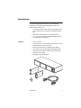
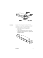
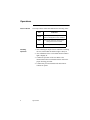
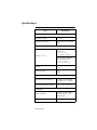
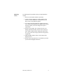
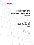
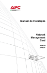
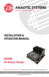
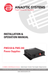
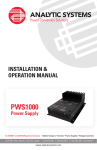
Triple Expansion
Chassis
AP9604
Installation Manual
®
Contents
Introduction . . . . . . . . . . . . . . . . . . . . . . . . . . . . . 1
Installation . . . . . . . . . . . . . . . . . . . . . . . . . . . . . . 2
Power Considerations . . . . . . . . . . . . . . . . . . . . . . 5
Operations . . . . . . . . . . . . . . . . . . . . . . . . . . . . . . 6
Specifications . . . . . . . . . . . . . . . . . . . . . . . . . . . . 7
Warranty and Service . . . . . . . . . . . . . . . . . . . . . . 8
Life-Support Policy . . . . . . . . . . . . . . . . . . . . . . . 10
Introduction
The APC® Triple Expansion Chassis is a 3-slot chassis
designed to accommodate APC management cards. The
Triple Chassis allows you to:
• Use cards with APC UPSs that are not equipped with a
card slot but do have an advanced Computer Interface
Port
• Add cards to UPSs that have an existing card slot
• Use cards such as the Environmental Monitoring Card
in a stand-alone configuration
Hardware
• Three card slots
• 9-pin male port for connecting the Triple Chassis to the
computer interface port of the UPS
• Power input connector for optional power adapter
• 9-pin female UPS monitoring port that duplicates the
functions of the computer interface port on the UPS
• Status indicator (LED)
• Mounting enclosure hardware
Introduction
1
Installation
The Triple Chassis can connect to any APC device equipped
with an advanced type computer interface port. This includes
certain Smart-UPS and Matrix-UPS products, and any other
management card that duplicates the functions of the UPSs
computer interface port, such as the Share-UPS.
Configurations
Desktop
installation
• Stand-alone desktop unit
• Mounted in a NetShelter (EIA-310-D) 19-inch
enclosure
The Triple Chassis is equipped with rubber feet for desktop use
and can be set up wherever space permits.
1. Place the Triple Chassis in its permanent location. It
should be located within 10 ft. (3.3 m) of the UPS. Make
sure that the front of the unit is accessible.
2. Connect the female end of the cable (940-1000A) to the
9-pin male connector labeled “To UPS” on the front of
the Triple Chassis.
3. Connect the male end of the cable to the 9-pin female
Computer Interface Port on the rear of the UPS.
4. If UPS monitoring is to be used, connect the required
cable (940-0024, not supplied) from the 9-pin
monitoring port on the front of the Triple Chassis to an
appropriate serial port on your computer, or to another
card.
5. If additional power is needed (see "Power Considerations" on page 5), connect the optional power adapter
output to the front of the Triple Chassis.
2
Installation
Rackmount
installation
The Triple Chassis is designed to mount in a NetShelter
enclosure (or other 19-inch EIA-310-D) using the hardware
included with the Triple Chassis. The Triple Chassis can be
installed in the enclosure by following these steps:
1. Peel the rubber feet from the bottom of the
Triple Chassis.
2. Attach a mounting bracket to each side of the Triple
Chassis using 2 small flat-head screws (supplied) and a
#2 Phillips screwdriver.
Installation
3
The mounting brackets can be attached at
various positions along the side of the Triple
Chassis using the holes provided. Choose a
position that will not cause the mounted
Triple Chassis or the attached cables to
interfere with closing the cabinet door or to otherwise
protrude from the cabinet. If more than two mounting
holes are aligned, choose the pair that are farthest apart.
3. Mount the Triple Chassis into the NetShelter enclosure
with 4 caged nuts and machine screws (not supplied).
If the Triple Chassis is being installed in a
enclosure other than a NetShelter, use the
hardware that is appropriate for the
enclosure.
4. Connect the female end of the included cable to the 9pin male connector labeled “To UPS” on the front of the
Triple Chassis.
5. Connect the male end of the cable to the 9-pin female
computer interface port on the rear of the UPS.
6. If UPS monitoring is to be used, connect the required
cable (940-0024, not supplied) from the 9-pin
monitoring port on the front of the Triple Chassis to an
appropriate serial port on a computer, or to another card.
7. If additional power is needed (see "Power Considerations" on page 5), connect the optional power adapter
output to the power port on the front of the
Triple Chassis.
4
Installation
Power Considerations
The power required for the operation of the card is normally
provided to the Triple Chassis by the UPS. There is a limit to
the amount of power available, and the total power required by
all the cards installed in the Triple Chassis must not exceed this
limit. If this limit is exceeded, it is likely that the management
product will cease to operate properly. The limits are:
• Smart-UPS — 200 mA
• Matrix-UPS — 200 mA
To determine the total amount of power required, add the
individual power requirements for each of the management
products to be installed in the Triple Chassis, as well as the
power requirements for the Triple Chassis itself. The power
requirements for each individual card can be obtained from the
documentation included with that card.
Optional power
adapter
In cases where the power requirements exceed 200 mA, APC’s
optional 24VDC (AP9505, not supplied) adapter may be used
to supplement the UPS power by providing an additional 400
mA. The power adapter is also required under the following
conditions:
• Smart-UPS models:
– Serial number prior to S9405
– Serial number starting with the letter W
– All Smart-UPS 250 models
• Matrix-UPS models:
– When remote turn-on of the UPS is required
The optional power adapter is used with
100/120 VAC power only. AP9505I is also
available for universal power input, but
requires a customer-supplied line cord.
If you need to obtain a power adapter, contact APC Customer
Service at a telephone number on the back cover.
Power Considerations
5
Operations
Status indicator
Checking
operation
The Triple Chassis status LED indicates the following states:
State
Indication
Bright
The Triple Chassis has power and at
least one management card is installed.
Dim
The Triple Chassis has power and no
management card is installed.
Off
The Triple Chassis has no power.
1. After installing the Triple Chassis and before installing
the card, confirm that the indicator light is dimly lit.
2. After installation of the card confirm that the indicator
light is brightly lit.
3. Confirm the operation of the card. Refer to the
documentation that was included with the card for the
proper checking procedure.
4. Confirm that previous installed cards and software
continue to operate.
6
Operations
Specifications
Item
Specification
Electrical
Operating voltage:
18 – 30 V
Operating current draw:
30 mA (exclusive of installed
card)
Physical
For desktop installation, with
rubber feet:
2.13 × 17 × 6.5 in
5.4 × 43.18 × 16.51 cm
Size (H × W × D):
For rack-mount installation,
with mounting brackets:
1.75 × 17 × 6.5 in
4.4 × 43.18 × 16.51 cm
Weight:
1.5 lb
0.7 kg
Shipping weight:
2 lb
0.9 kg
Environmental
Operating elevation (storage):
0 to 1000 ft (0 to 50 000 ft)
0 to 3000 m (0 to 15 000 m)
Operating temperature (storage):
–5 to 45 °C (–25 to 65 °C)
23 to 113 °F (–13 to 149 °F)
Approvals
EMC verification:
FCC Class A, DoC Class A,
EN55022 Class A, VCCI,
AS/NZS 3548
Electromagnetic immunity:
EN50024 verified
Specifications
7
Warranty and Service
Limited
warranty
APC warrants the Triple Expansion Chassis to be free from
defects in materials and workmanship for a period of two years
from the date of purchase. Its obligation under this warranty is
limited to repairing or replacing, at its own sole option, any
such defective products. This warranty does not apply to
equipment that has been damaged by accident, negligence, or
misapplication or has been altered or modified in any way. This
warranty applies only to the original purchaser.
Warranty
limitations
Except as provided herein, APC makes no warranties, express
or implied, including warranties of merchantability and fitness
for a particular purpose. Some jurisdictions do not permit
limitation or exclusion of implied warranties; therefore, the
aforesaid limitation(s) or exclusion(s) may not apply to the
purchaser.
Except as provided above, in no event will APC be liable for
direct, indirect, special, incidental, or consequential damages
arising out of the use of this product, even if advised of the
possibility of such damage.
Specifically, APC is not liable for any costs, such as lost profits
or revenue, loss of equipment, loss of use of equipment, loss of
software, loss of data, costs of substitutes, claims by third
parties, or otherwise. This warranty gives you specific legal
rights and you may also have other rights, which vary
according to jurisdiction.
8
Warranty and Service
Obtaining
service
To obtain support for problems with your Triple Expansion
Chassis:
0
1. Note the serial number and date of purchase.
2. Contact Customer Support at a phone number on the
back cover of this document. A technician will try to
help you solve the problem by phone.
3. If you must return the product, the technician will give
you a return material authorization (RMA) number. If the
warranty expired, you will be charged for repair or
replacement.
4. Pack the unit carefully. The warranty does not cover
damage sustained in transit. Enclose a letter with your
name, address, RMA number and daytime phone number; a copy of the sales receipt; and a check as payment,
if applicable.
5. Mark the RMA number clearly on the outside of the
shipping carton.
6. Ship by insured, prepaid carrier to the address provided
by the Customer Support technician.
Warranty and Service
9
Life-Support Policy
General policy
American Power Conversion (APC) does not recommend the
use of any of its products in the following situations:
• In life-support applications where failure or malfunction
of the APC product can be reasonably expected to cause
failure of the life-support device or to affect
significantly its safety or effectiveness.
• In direct patient care.
APC will not knowingly sell its products for use in such
applications unless it receives in writing assurances
satisfactory to APC that (a) the risks of injury or damage have
been minimized, (b) the customer assumes all such risks, and
(c) the liability of American Power Conversion is adequately
protected under the circumstances.
Examples of
life-support
devices
The term life-support device includes but is not limited to
neonatal oxygen analyzers, nerve stimulators (whether used for
anesthesia, pain relief, or other purposes), autotransfusion
devices, blood pumps, defibrillators, arrhythmia detectors and
alarms, pacemakers, hemodialysis systems, peritoneal dialysis
systems, neonatal ventilator incubators, ventilators (for adults
and infants), anesthesia ventilators, infusion pumps, and any
other devices designated as “critical” by the U.S. FDA.
Hospital-grade wiring devices and leakage current protection
may be ordered as options on many APC UPS systems. APC
does not claim that units with this modifications are certified or
listed as hospital-grade by APC or any other organization.
Therefore these units do not meet the requirements for use in
direct patient care.
10
Life-Support Policy
Radio Frequency Interference
Warning
Changes or modifications to this unit not expressly
approved by the party responsible for compliance
could void the user's authority to operate this
equipment.
This equipment has been tested and found to comply with the
limits for a Class A digital device, pursuant to part 15 of the
FCC Rules. These limits are designed to provide reasonable
protection against harmful interference when the equipment is
operated in a commercial environment. This equipment
generates, uses, and can radiate radio frequency energy and, if
not installed and used in accordance with this user manual,
may cause harmful interference to radio communications.
Operation of this equipment in a residential area is likely to
cause harmful interference. The user will bear sole
responsibility for correcting such interference.
This Class A digital apparatus complies with Canadian
ICES-003.
Cet appareil numérique de la classe A est conforme à la norme
NMB-003 du Canada.
®
APC Worldwide Customer Support
Customer support for this or any other APC product is available at no charge in any of the
following ways:
• Visit the APC Web site to find answers to frequently asked questions (FAQs), to access
documents in the APC Knowledge Base, and to submit customer support requests.
– www.apc.com (Corporate Headquarters)
Connect to localized APC Web sites for specific countries, each of which
provides customer support information.
– www.apc.com/support/
Global support with FAQs, knowledge base, and e-support.
• Contact an APC Customer Support center by telephone or e-mail.
– Regional centers:
APC Headquarters
U.S.&Canada
(1) (800) 800-4272 (toll free)
Latin America
(1) (401) 789-5735 (USA)
Europe, Middle
East, Africa
(353) (91) 702020 (Ireland)
Japan
(03) 5434-2021 Guidance 3
– Local, country-specific centers: go to www.apc.com/support/contact for contact
information.
Contact the APC representative or other distributor from whom you purchased your APC
product for information on how to obtain local customer support.
Entire contents copyright © 2002 American Power Conversion. All rights reserved.
Reproduction in whole or in part without permission is prohibited. APC, Share-UPS,
Matrix-UPS, NetShelter, and the APC logo are trademarks of American Power
Conversion Corporation and may be registered in some jurisdictions. All other
trademarks, product names, and corporate names are the property of their respective
owners and are used for informational purposes only.
990-0145C
01/2002