1
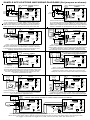
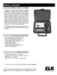
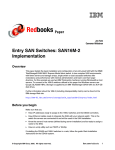
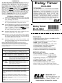
OVERVIEW
The ELK-960 features adjustable delay time of one (1)
second to approximately sixty (60) minutes. It can be
operated by 12 to 24 volts D.C. and can be triggered
by a negative (-) or positive (+) voltage. The operating
mode and the relay condition can be set as follows:
BEGIN- Relay turns on when triggered and back off
when delay time expires. END- Relay turns off when
triggered and back on when delay time expires. The
delay time can start when the trigger is first applied (B
mode) or when the trigger is removed (A mode). The
ELK-960 relay can be set to provide a single 1-SHOT
output or to REPEAT (pulse on and off). All options
are selected using easy to change mini-jumpers.
TERMINAL DESCRIPTIONS
+
Positive power input. Connect a +12 to +24 Volts
D.C. source. Warning: Do not exceed +24 Volts
D.C., Damage will occur.
-
Negative power (ground) input. Connect to a negative or ground terminal of the power source.
TGR Trigger voltage input. Connect a 4.5 to 24VDC trigger
source. Place jumper JP5 (TRIGGER POLARITY) in
the "+" position to trigger from a positive voltage or
in the "-" position to trigger from a negative. The
trigger voltage may be 4.5 to 24VDC, regardless of
the main powered input (12Vdc to 24VDC).
N/O
Normally Open side of the relay contacts. No connection to COM when the relay is off.
COM Common or "pole" side of the relay contacts. When
the relay is off, COM is internally connected with the
N/C contact. When the relay is on, COM is internally
connected with the N/O contact.
N/C
Normally Closed side of the relay contacts. This
terminal is internally connected with the COM terminal when the relay is off.
NOTE: The ELK-960 automatically triggers (turns on) and runs
through a delay cycle when first powered up. To reduce waiting time
and speed up installation, set jumper JP1 to SEConds and adjust R3
to 1 before applying power. Once power is applied, change the
settings as required.
SETTINGS AND JUMPER DESCRIPTIONS
R3 This knob is used to increase or decrease the delay time
from 1 to 60. Full clockwise is 1, halfway is 30, full
counter-clockwise is 60. The arrow is a reference point.
JP1 SEC = Delay time in seconds. Adjustable from 1 ~ 60.1
MIN = Delay time in minutes. Adjustable from 1 ~ 60.1
JP2 REPEAT = (Adjustable pulse) Relay cycles ON / OFF at
delay time interval using a 50/50 duty cycle.2
A trigger input will temporarily stop the cycle.
1-SHOT = Relay activates only once per trigger.
JP3 END
= Relay turns
when delay
BEGIN = Relay turns
when delay
off when triggered and back on
time expires.
on when triggered and back off
time expires.
Delay Timer
ELK-960
APPLICATION:
The ELK-960 is an economical and flexible
solution for many general-purpose time delay
applications. The unit operates on 12 to 24
Volts D.C. and can be selected for positive or
negative trigger logic. Setup is easy with
thumbwheel adjustment between 1 and 60
seconds, a quick jumper setting converts the
time from seconds to minutes. The timer can be
configured to activate once for each trigger, or
pulse as soon as power is applied.
Delay Timer
ELK-960
Economical Time Delay Relay Module
FEATURES:
• Operating Voltage Range: 12 to 24 Volts D.C.
• Adjustable Delay Time.
• Positive or Negative Low Current Trigger.
• SPDT (Form "C") Relay.
• Selectable Initial Relay State: ON / OFF.
• Output Modes: One-Shot or Repeat.
• LED Indication of Relay Status.
• Lifetime Limited Warranty, call for details.
• Packed In Reusable Poly Storage Box.
SPECIFICATIONS:
• Time Settings: 1 Sec to ~ 60 Min.
• Relay Contact Rating: 7A @ 30 VDC.
10A @ 125 VAC.
• Operating Voltage: 12 to 24 Volts D.C.
• Trigger Voltage: 4.5 - 24 Volts D.C.
• Input Trigger Current: 1.2 mA.
• Current Draw With Relay On: 40mA.
• Size: 3"x2.2"x1" (Fits Std.Snap Track).
Features and Specifications subject to change without notice.
JP4 A = Delay time starts when trigger is removed.
B = Delay time starts when trigger is first applied.
JP5 +
-
= Selects positive polarity for the input trigger.
= Selects negative polarity for the input trigger.
1
Times are approximate. When adjusted to the highest
setting (60 minutes) the actual time delay will be slightly
greater.
HINT: For a delay time in minutes, adjust and test with
jumper JP1 in the SEConds position. (IE: For a 15 minute
delay, adjust and test to 15 seconds) Then move jumper JP1
to MINutes. This quickly provides a reasonable equivalent
delay time in minutes.
2
A 50/50 duty cycle means the OFF and ON times will be
equal.
03/04
828-397-4200 Voice
828-397-4415 Fax
http://www.elkproducts.com
email: [email protected]
PO Box 100 • Hwy. 70W • Hildebran, NC 28637 • USA
Instructions Printed On Inside
SAMPLE APPLICATIONS AND WIRING DIAGRAMS (Set jumpers as shown)
-
DOOR STRIKE HOLD
TIMER
1
+
JP5
N/O
Pushbutton
+
- +
N/O
BEGIN
COM
-
LED
DOOR PROP ALARM
TIMER
22K Ohm
Resistor
-
N/C
JP5
N/O
N/C
120V
LIGHT
B
MIN
REPEAT
1-SHOT
END
BEGIN
TRIGGER
MODE
K1
COM
A
LED
TGR
- +
SEC
JP3
BEGIN
TRIGGER
MODE
K1
Hot
120VAC
Supply
TRIGGER
POLARITY
JP2
N/C
END
+
JP1
Delay Timer
1-SHOT
JP3
COM
TIME 1 - 60
ELK-960
JP5
N/O
AUTOMATIC LIGHT
CONTROL
R3
TGR
N/C
CONTACT ON
DOOR
4
+
COM
REPEAT
JP2
- +
JP4
+
MIN
TRIGGER
POLARITY
+
+
-
-
SEC
JP1
R3
Delay Timer
-
12 Volts DC
Power Supply
Motion
Detector
TIME 1 - 60
ELK-960
SIREN
BEGIN
Used to extend the release time of an access control device
or to manually activate a door maglock release device. The
trigger is activated by a contact closure or a N/O pushbutton
and the door maglock remains released (door open) after the
button is released for the delay time set up in the ELK-960.
-
3
+
END
B
JP4
Used to extend the release time of an access control device
or to manually activate a door strike release device. The
trigger is activated by a contact closure or a N/O pushbutton
and the door strike remains activated (door open) after the
button is released for the delay time set up in the ELK-960.
-
1-SHOT
A
B
LED
12 Volts DC
Power Supply
REPEAT
TRIGGER
MODE
K1
N/C
A
MIN
JP3
N/C
12/24V
MAGLOCK
END
TRIGGER
MODE
K1
TGR
-
SEC
JP2
COM
+
TRIGGER
POLARITY
JP1
N/O
Delay Timer
R3
N/O
Pushbutton
1-SHOT
JP5
JP3
+
TIME 1 - 60
ELK-960
REPEAT
JP2
TGR
MAGLOCK RELEASE
TIMER
MIN
TRIGGER
POLARITY
- +
2
+
SEC
JP1
-
R3
Delay Timer
12/24V
DOOR
STRIKE
-
TIME 1 - 60
ELK-960
+
12/24 Volts DC
Power Supply
-
12/24 Volts DC
Power Supply
A
B
JP4
LED
JP4
Neutral
Delay is started when the door is opened. If the door
remains opened after the time delay has expired the relay
will turn on and remain on until the door is closed. If the door
is closed before the time delay expires the ELK-960 is reset
awaiting another input from the door contact.
+ ARMED
OUTPUT
12V AUX
-
+
EXIT DELAY
SHUNT TIMER
TIME 1 - 60
ELK-960
JP5
1-SHOT
-
N/C
N/C
CONTACT
BEGIN
N/C
-
JP2
Delay Timer
BEGIN
+
-
JP4
Useful for adding a cut-off timer to a control panel that does
not have one. It can also be used to shorten the cut-off timer
for a control with no adjustable timer.
9
+
N/C
REPEAT
1-SHOT
END
BEGIN
A
+
B
LED
JP4
Converts a steady output to pulsing, suitable for flashing a light
or pulsing an audible device. Note: Alarm output must be
capable of supplying enough current to drive the bell and light.
1-SHOT
BEGIN
A
-
B
JP4
#1
TGR
JP5
120VAC
Supply
Hot
N/O
COM
120V
LIGHT
N/C
K1
TRIGGER
MODE
SEC
MIN
REPEAT
1-SHOT
END
BEGIN
A
B
LED
Neutral
- +
JP3
TRIGGER
MODE
REPEAT
END
+
TRIGGER
POLARITY
JP2
JP3
K1
TIME 1 - 60
Delay Timer
MIN
JP1
JP2
N/O
SEC
R3
JP5
- +
JP1
TGR
LED
-
MIN
TRIGGER
MODE
K1
COM
ELK-960
R3
+
TRIGGER
POLARITY
N/C
-
- +
N/O
TIME 1 - 60
Delay Timer
COM
JP5
SEC
USING TWO 960'S TO DELAY THEN THEN TOGGLE A RELAY
ELK-960
N/O
SWITCH
TGR
-
-
12V
LIGHT
or LED
12V Bell
or Siren
B
12 Volts DC
Power Supply
TRIGGER
POLARITY
JP3
END
A
LED
+
1-SHOT
JP3
N/C
TIME 1 - 60
ELK-960
REPEAT
TRIGGER
MODE
K1
COM
+
MIN
JP2
JP5
BEGIN
BELL OR LIGHT
FLASHER
JP1
TGR
- +
N/O
+
12V ALARM
OUTPUT
R3
TRIGGER
POLARITY
END
JP4
8
CONTROL PANEL
SEC
JP1
R3
+
1-SHOT
When contact opens, relay is turned on which causes
instant zone violation. Contact reclosure will cancel trigger
applied by resistor. Delay starts when contact closes.
Relay turns off and zone restores after delay time expires.
TIME 1 - 60
Delay Timer
REPEAT
B
ALARM CUT-OFF
TIMER
ELK-960
MIN
A
LED
-
+
SEC
TRIGGER
MODE
K1
COM
JP4
7
12V ALARM
OUTPUT
-
JP5
B
LED
CONTROL PANEL
12V Bell
or Siren
TGR
- +
N/O
A
Provides an exit delay to an otherwise instant alarm loop.
The ELK-960 is triggered by the control's Armed output. The
door contact is then shunted by the relay contacts. After the
user has exited and the delay time has expired, the door
contact is restored into the loop.
-
+
TRIGGER
POLARITY
JP3
END
TRIGGER
MODE
K1
Delay Timer
22K Ohm
Resistor
REPEAT
JP3
COM
TIME 1 - 60
ELK-960
MIN
JP2
N/O
6
JP2
TGR
- +
+
JP1
TRIGGER
POLARITY
-
INSTANT ACTIVATION OF ZONE
WITH DELAYED RESTORAL
R3
+
12V AUX
SEC
JP1
R3
Delay Timer
N/C
CONTACT ON
EXIT DOOR
CONTROL PANEL
CLOSED
ZONE
-
5
CONTROL PANEL
CLOSED
ZONE
INPUT
For turning on an interior or exterior light with a motion
detector. When motion is detected, the ELK-960 is triggered
and the light is turned on. The amount of time the light remains
on after the detector resets is adjustable. Delay time will
automatically restart each time the motion detector activates.
JP4
#2
Used for delaying a trigger then toggling a relay on/off. ELK-960 #1 starts a time delay when the N/O switch is closed.
When 960 #1's time delay expires, 960 #2 is triggered turning it's relay on for the time delay setting , then turning the relay
off. (toggle) To sumarize: fire trigger on #1, waits, turns on #2's relay, waits, then turns relay off.