1
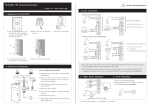
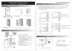
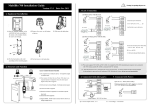
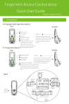
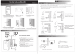
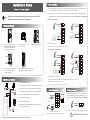
Installation Guide
3.Lock Connection
(1) The system supports NO lock and NC lock. For example the NO lock (normally open at power on) is connected with "NO"
Version: 1.1 Date: May, 2013
and "COM" terminals, and the NC lock is connected with "NC" and "COM" terminals.
(2) When the electrical lock is connected to the Access Control System, you need to connect one FR107 diode (shipped in package) in
Note:
Registering user information and fingerprint, we must use the ACCESS3.5
Software and fingerprint USB sensor, then upload .
parallel with the connection to prevent self-inductance EMF feedback the system. NB: Do not reverse the polarities!
1) Share power with the lock:
+
1.Equipment Installation
-
Red
+12V
Black
GND
+
-
Purple BELL-
White
SEN
Black
GND
Gray
BUT
DC12V
Instruction for the Mounting Paper
NC LOCK
-
+
Before the device is fastened, please
stick the paper to the place where you
want to install it, then make holes and
lay cables according to the mounting
paper.
FR 107
Wiring Hole
10
+
Fixing Hole
-
11
12
13
Blue
NO1
Red
COM1
Yellow
NC1
Orange
NO2
-
FR 107
+
Green COM2
(1) Paste the mounting template on
the wall. Drill the holes according
to the marks on the template
(holes for screws and wiring).
(2) Remove the screws on the
bottom of device.
(3) Take away the back plate.
White
SEN
Black
GND
Gray
BUT
Blue
NO1
Red
COM1
Yellow
NC1
Orange
NO2
Green COM2
Device share power with the lock:
ULOCK=12V, I-ILOCK>1A……①; And the distance between the lock and the device is ≤10 meters.
2) Does not share power with the lock:
+
Red
+12V
Black
GND
+
DC12V
Purple BELL-
+
-
DC12V
Brown BELL+
DC power
-
(5) Place the unit onto the mounting bracket, and
tighten the screws at the bottom of the unit.
+
FR 107
+
-
NC LOCK
2. Structure and Function
White
SEN
Black
GND
Gray
BUT
Blue
NO1
Red
COM1
Yellow
NC1
Orange
NO2
Green
COM2
-
+
(4) Fix the rubber pad and the back
plate on the wall according to
the mounting paper.
GND
Brown BELL+
NO LOCK
-
(only for your reference)
+
Mounting Paper
+12V
Purple BELL-
Brown BELL+
DC12V
Fixing Hole
Fixing Hole
Red
Black
NO LOCK
Red
+12V
Black
GND
Purple BELL-
FR 107
+
+
DC power
Brown BELL+
White
SEN
Black
GND
Gray
BUT
Blue
NO1
Red
COM1
Yellow
NC1
Orange
NO2
Green
COM2
Device does not share power with the lock:
2.Structure and Function
A. ULOCK=12V, I-ILOCK≤1A; B. ULOCK≠12V; C. The distance between the lock and the device is >10 meters.
Access Control System Function
D. We suggest user does not share power with the lock.
①:‘I’: device output current, ‘ULOCK’: lock voltage,‘ILOCK’: lock current.
(1) If a registered user verified, the device will send a signal to unlock the door.
TCP/IP
RS485
RS485 Converter
(2) The door sensor will detect the ON-OFF state. If the door is unexpectedly
⑥
⑤
④
①
Exit
Exit Switch
②
4. Other Connections
Lock Sensor
(3) If the device is illegally removed, the device will signal the alarm.
(4) External card reader is supported.
(5) External exit button is supported.
External Reader
5. Power Connection
opened or improperly closed, the alarm signal (digital value) will be triggered.
(6) Supports RS485, TCP/IP communication to be able to connect with a PC. One
PC can manage multiple devices.
③
Alarm
Exit
Exit Button
Alarm Power
-
Alarm
White
SEN
Black
GND
Gray
BUT
Blue
NO1
Red
COM1
Yellow
NC1
Orange
NO2
Green
COM2
+
The5.
device
Power
workingConnection:
voltage DC 12V, electric current 500mA
(50mA for standby current). Positive is connected with‘+12V’;
negative is connect with ’GND’ (do not reverse the polarities).
+
Door Sensor
-
Red
+12V
Black
GND
DC12V
Alarm Voltage output ≤ DC 12V
! WARNING: Do Not operate with Power connected.
* Reserves the final rights of modification and interpretation by our company.
6. Wiegand Output
7. Wiegand Input
The device supports standard Wiegand ,
26-bit output, so you can connect it with
various access control devices.
The device has a Wiegand input port, which enables the connection
to a slave card reader. Devices are control devices on both sides
of the door to control the access and electric lock.
Access Control Panel
DATA0
DATA1
GND
RS485 Reader Function:
Equipment supports RS485reader function, can be through RS485communication connected to FR1200 reader.
FR1200 reader for slaver, achieve RS485 Anti-passback functions. If select “RS485reader function” , so device
can not connect with PC through RS485 communications.
Diagram of the device connect to reader as below(The device act master):
+12V
Red
+12V
Black
GND
Green
WD0
White
WD1
Black
GND
Blue
485+
Blue
RLED
Yellow
485-
Gray
GLED
Purple
BEEP
White
IWD1
Green
IWD0
GND
485+
Yellow
DATA1
485-
Purple
DATA0
+12V
Red
RLED
GND
Black
GLED
Reader
Access Control Device
BEEP
Diagram of the device connect to controller as below (The device act slaver):
(1) Do not exceed 90m (meters) distance between the Device and Access Control Lock OR Card reader.
(In the case of long distance installation, use the Wiegand Signal Extender, to minimise interference.)
SWITCH
(2) To keep a balanced and stable Wiegand signal, connect the device, access control lock or card reader
on the same "GND"(ground) port.
GND
485-
485+
GND
+12V
(separate power supplies)
GND
+12V
(separate power supplies)
PWR
STATE
EXT
RS485
PC
RS485
8.Other Functions & Features
(1) Tamper Function:
When installing device, user need to put the magnet between the device
and the back plate. If the device is being illegally removed, the magnet
loses connectivity and will trigger the alarm.
(2) Restore Factory Settings:
Operation: Between 30 – 60 seconds after the tamper alarm has sounded,
press the tamper switch 3x times.
(3) Device mould is manufactured from fireproof material.
(4) Working temperature: -40℃ ~ +45℃.
Front View
Back View
#1 Reader
#2 Reader
#3 Reader
...
#8 Reader
Set the RS485 address (device number) by Access3.5 software.
(2) TCP/IP Mode:
Two ways for TCP/IP connection.
(A)Crossover cable: The device and PC connected directly.
(B)Straight cable: The device and PC connected to
LAN/WAN through switch/Lanswitch.
Tamper
Magnet
Switch
…
9. Communication
There are two modes that the PC software communicate and exchange information with the device:
RS485 and TCP/IP, and supports remote control.
(1) RS485 Mode:
Please use specified RS485 wire, RS232/485 active converter
and bus-type wiring. When the distance is long, it is need to
parallel a terminal resistance and the value is 120 ohm.
IP Address:192.168.1.201
Subnet Mask:255.255.255.0
Terminals definition as below:
Terminals
PC Serial Ports
485+
RS485+
485-
RS485-
10. Caution:
(1) Connect the power cable after al the wiring has been completed. If the device is working abnormally,
please shut down the device, and make necessary checks. Please note that any "HOT SWOP" of wiring on
the device may damage the device, and the warranty does not cover damage caused by improper operations.
485+
485-
(2) We recommend use the DC 12V/3A power supply. Please contact our technical staff for details.
485+ 485-
RS485
Converter
IP Address:192.168.1.124
Subnet Mask:255.255.255.0
(3) Please read the terminal and wiring description and diagrams carefully before commencing with
installations. Any damage to the device caused by improper operations, will not be covered under warranty.
RS485 Bus
485+
485-
485+
485-
(4) Keep the exposed part of wire less than 5mm, to avoid unexpected connection.
(5) Please connect the 'GND' when starting installations, especially in an environment where static electricity
is very high.
(6) Do not change the cable type in case of a long distance installations.
* Reserves the final rights of modification and interpretation by our company.
! WARNING: Do Not operate with Power connected.