1
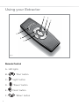
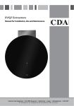
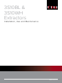
3S10BL &
3S10WH
Extractors
Installation, Use and Maintenance
Customer Care Department • The
Group Ltd. • Harby Road • Langar • Nottinghamshire • NG13 9HY
T : 01949 862 012 F : 01949 862 003 E : [email protected] W : www.cda.eu
www.cda.eu
Important
The CDA Group Ltd cannot be held responsible for injuries or losses
caused by incorrect use or installation of this product. Please note
that CDA reserve the right to invalidate the guarantee supplied with
this product following incorrect installation or misuse of the appliance
or use in a commercial environment.
This appliance is not designed to be used by people (including
children) with reduced physical, sensorial or mental capacity, or
who lack experience or knowledge about it, unless they have had
supervision or instructions on how to use the appliance by someone
who is responsible for their safety.
Under no circumstances should any external covers be removed for
servicing or maintenance except by suitably qualified personnel.
Appliance information:
Please enter the details on the appliance rating plate below for
reference, to assist CDA Customer Care in the event of a fault with
your appliance and to register your appliance for guarantee purposes.
Appliance Model
Serial Number
CE Declarations of Conformity:
This appliance has been manufactured to the strictest standards and
complies with all applicable legislation, including Gas safety, Electrical
safety (LVD) and Electromagnetic Interference Compatibility (EMC).
2
IMPORTANT INFORMATION FOR CORRECT DISPOSAL OF THE
PRODUCT IN ACCORDANCE WITH EC DIRECTIVE 2002/96/EC.
At the end of its working life, the product must be taken to a special
local authority waste collection centre or to a dealer providing
appliance recycling services.
Disposing of a household appliance separately avoids possible
negative consequences for the environment and health. It also
enables the constituent materials to be recovered, saving both energy
and resources. As a reminder of the need to dispose of household
appliances separately, the product is marked with a crossed-out
wheeled dustbin .
Please note:
• This appliance is designed to recirculate air only, under no
circumstances should it be connected to any ductwork or
external venting system.
• Do not use silicone sealant to secure the extractor to the ceiling.
• You must be able to isolate the extractor from the mains electrical
supply after installation.
• Steam cleaners must not be used when cleaning this appliance.
• The performance of your extractor will vary depending on a number
of factors, such as supply voltage and cleanliness of the filters.
Note:
For best performance, you should switch on the extractor 15 minutes
before starting to cook and leave it to run for approximately 15
minutes after the end of cooking.
3
Using your Extractor
D
E
F
A
B
C
Fig. 1
Remote Control
A - LED lights
BCDEF4
“Plus” button
“Light” button
“Power” button
“Clock” button
“Minus” button
To switch the extractor on or off:
• Press the “Power” button “D” once. After switching on the motor
will automatically start at the lowest speed setting.
Setting the extractor speed when it is running:
The extractor may run at a choice of 4 speeds, indicated by the LED
lights on the remote control.
• To increase the speed press the “Plus” button “B”. The speed will
increase by one increment for each push of this button.
• To decrease the speed press the “Minus” button “F”. The speed
will decrease by one increment for each push of this button until it
reaches speed 2.
• To switch from a higher speed to the lowest one it is necessary to
press the “Power” button “D” twice (once to switch the motor off
then second time to restart it at the lowest speed).
To switch the light on or off:
• Press the “Light” button “C”.
The timer function:
The timer function sets the extractor to switch itself off after ten
minutes have passed. This is ideal when you leave the kitchen after
cooking as the extractor can be left to clear the air then switch off to
save power, without you disturbing your meal to switch it off.
• To set this function, press the “Timer” button “E”; the right hand
LED on the remote control will start to flash slowly (once every five
seconds).
• To cancel this function, press either the “Plus” or “Minus” button “B”
or “F” on the remote control.
5
Care and Maintenance
IMPORTANT : DO NOT PERFORM
MAINTENANCE OR CLEANING OF
THE EXTRACTOR WITHOUT FIRST
SWITCHING OFF THE ELECTRICITY
SUPPLY.
Cleaning
You should use a nonabrasive cleaner.
Any abrasive cleaner (including Cif) will
scratch the surface.
You can clean your extractor effectively
by simply using a dilute solution of
water and mild detergent and drying to
a shine with a clean cloth, for example
the CDA E-Cloth.
͘ϭϭ
Fig. 2
B
A
C
Fig. 3
Cleaning the grease filters
The grease filters should be kept clean to minimise the risk of fire.
The grease filters may be removed then cleaned with hot soapy
water. You can also wash the grease filters in a dishwasher, ensuring
that you place them in an upright position to prevent damage from
other items in the dishwasher.
Please note:
Cleaning the grease filters in the dishwasher may lead to
discolouration. This is normal and does not constitute a fault with the
appliance.
6
To remove the aluminium grease filters for cleaning
• While supporting the weight of the lower half of the globe, use the
special tool supplied with the appliance to unscrew the metal ring
that secures it (Fig. 2).
• Place the lower half of the globe, chrome lower cover and locking
ring aside safely.
• Slacken one of the retaining screws (“A” in Fig. 3) by a maximum of
one turn.
• Swing the retaining tab (“B” in Fig. 3) aside to release the carbon
filter and aluminium grease filter.
• Pull the carbon filter and aluminium grease filter downward from
their housing.
• Repeat this to remove the second set of carbon filter and aluminium
grease filter.
To re-fit the aluminium grease filters after cleaning
• Slide one carbon filter and one aluminium grease filter back into
the housing on one side of the motor, ensuring that the aluminium
grease filter is located furthest from the motor itself.
• Swing the retaining tab (“B” in Fig. 3) into position to hold the filters
in place.
• Tighten the retaining screw (“A” in Fig. 3) to secure the retaining tab
in position.
• Fit the other carbon filter and aluminium grease filter in a similar way.
• Relocate the lower half of the globe and chrome lower cover to the
extractor body, then secure them using the locking ring, removed
earlier. Tighten this hand-tight using the special tool supplied with
the appliance.
7
Changing the charcoal filter
(Filter part number CHA30)
To ensure best performance of your extractor, you should replace the
charcoal filter every four to six months, depending on use.
To replace the charcoal filters:
• The charcoal filters are removed as part of the grease filter cleaning
process described on the previous page. Refer to this for charcoal
filter replacement.
IMPORTANT: Steam cleaners must not be used to clean this
appliance.
8
If your extractor is not working:
1. Check that the mains supply has not been switched off.
2. Check that the fuse in the spur has not blown.
3. There is a hidden on/off switch inside the body of the
globe. Ensure that this has not been accidentally switched
off during installation or maintenance. This switch is shown
as “C” in Fig. 3.
9
The LED and Neon Lamps
The LED lamps (3S10BL) and neon light tubes (3S10WH) are long-life
items that are not designed to be replaced by the user. In the unlikely
event of a lamp failure, contact CDA Customer Care for assistance.
Mains Electricity Connection
THIS APPLIANCE MUST BE CONNECTED TO THE MAINS SUPPLY
BY A COMPETENT PERSON, USING FIXED WIRING VIA A DOUBLE
POLE SWITCHED FUSED SPUR OUTLET AND PROTECTED BY A
3A FUSE.
DOUBLE POLE
SWITCHED
FUSED SPUR OUTLET
We recommend that the appliance is
connected by a qualified electrician,
who is a member of the N.I.C.E.I.C. and
who will comply with the I.E.T. and local
regulations.
The wires in the mains lead of this
appliance are coloured in accordance
with the following code:
Green & Yellow = Earth
Blue = Neutral
Brown = Live
Fig. 4
USE A 3 AMP FUSE
As the colours of the wires in the mains lead for the appliance may
not correspond with the coloured markings identifying the terminals
connecting to the fused spur, proceed as follows:
10
•The wire which is coloured green and yellow must be connected to
the terminal marked “E” (Earth) or coloured green.
•The wire which is coloured blue must be connected to the terminal
marked “N” (Neutral) or coloured black.
•The wire which is coloured brown must be connected to the
terminal marked “L” (Live) or coloured red.
Note: Use a 3A Fuse.
Assembly and electrical connection
should be carried out by specialised
personnel.
When installing this product we
recommend you seek the help of
another individual.
Electrical Information
Mains electrical voltage: 230Vac
Total rated power consumption:
3S10BL: 143W
3S10WH: 220W
11
Mounting Your Extractor
This appliance is designed to
recirculate air only, under no
circumstances should it be connected
to any ductwork or external venting
system.
When installing this appliance over a
CDA hob, the clearance between the
extractor and the hob must be equal
to or exceed 650mm. This instruction
overrides the instructions supplied with
the CDA hob. (The height should be
measured from the top of the hotplates
or burners).
Gas: 650mm minimum
Electric: 650mm minimum
Fig. 5
Where the extractor is to be installed above a non-CDA hob, the
instructions supplied with the hob may dictate that the height required
above the hob is greater than 650mm.
IN THE ABSENCE OF ANY INSTRUCTIONS SUPPLIED WITH A
GAS HOB, THE MINIMUM DISTANCE BETWEEN THE HOB AND
EXTRACTOR MUST BE AT LEAST 760mm.
12
Installation
1. Thread the safety cable upward
through the small hole in the ceiling
plate then downward through the
centre boss. Pull this tight so the end
nipple rests against the ceiling plate
(Fig. 6).
2. Pass the fixed wiring from the ceiling
through the large hole in the ceiling
plate (shown as “A” in Fig. 7) and fix
this plate to the ceiling using suitable
fixings. The ceiling fixings supplied
with this appliance are designed for
fitting to a solid masonry or concrete
ceiling. If mounting the appliance to
any other type of ceiling the installer
must:
• Use their own expertise and
discretion to select suitable
fixings to support the weight of
the appliance.
`•Ensure that the ceiling is strong
enough to support the weight
of the extractor: Strengthening
the ceiling as necessary is the
responsibility of the installer.
Fig. 6
Fig. 7
A
Fig. 8
13
2. Remove the chrome cover from the
top of the sphere, then remove and
discard the cylindrical packing piece
from the top bracket within it (Fig. 8).
3. Pass the power cable that exits the
appliance up through the central
bracket within the sphere (Fig. 9).
4. Select the larger diameter hanging
tube and pre-assemble this to the
sphere (Fig. 10):
`•Thread the power cable through
the top chrome cover and locate
this cover back onto the globe.
`•Pass the power cable through
the tube ensuring that it enters
through the plain end and exits
the end with the joining piece
fitted.
5. Slide the top cover up the hanging
tube then fit this tube to the sphere
(Figs. 11 & 12). Secure the tube to the
central bracket with two supplied
bolts and nuts.
`
Fig. 9
Fig. 10
Fig. 11
Fig. 12
14
6. Select the smaller diameter hanging
tube and pass it through the ceiling
rose cover. Note that the end of the
hanging tube with holes in it needs to
be upper-most (Fig. 13).
7. Thread the power cable from the
sphere upward through the smaller
diameter hanging tube.
Important: Ensure that the power
cable exits through the larger hole in
the side of the tube near the top end
(Fig. 13).
Fig. 13
8. Slide the upper hanging tube inside
the lower hanging tube (Fig. 14).
Fig. 14
9. Tighten the three grubscrews to lock
the two sections of the hanging tube
together (Fig.15). Important: These
grubscrews must be fully tightened
as they support the weight of the
sphere.
Fig. 15
15
10. With a second person supporting
the weight of the sphere, thread
the safety cable down the tube
assembly (Fig. 16) so it exits within
the top cavity of the sphere (Fig. 17).
Fig. 16
Fig. 17
11. Insert the top tube into the ceiling
bracket and secure it with two
supplied through-bolts and nuts (Fig
18).
Fig. 18
12. Pass the end of the safety cable up
through its hole in the top of the
sphere (marked “A” in Fig. 19). Then
fit the cable clamp to it.
A
Fig. 19
16
11. With an assistant supporting the
weight of the sphere, adjust the
height by sliding the outer hanging
tube up or down the inner one (Fig.
20).
12 Fix the height adjustment by locking
the three grubscrews on the tube
joining-piece (shown as in Fig. 15).
Fig. 20
NOTE the security of the height
adjusting grubscrews should be
double-checked at this stage.
13. Pull the safety cable tight at the
lower end (pulling through the hole
“A” in Fig. 19), then tighten the clamp
on the safety cable against this face.
14. Make all necessary electrical
connections.
15. Slide the ceiling rose cover up to
conceal the fittings. This is held in
position by a single grubscrew (Fig.
21).
Fig. 21
17
Notes:
18
Notes:
E & O E. All instructions, dimensions and illustrations are provided for guidance only. CDA reserve the
right to change specifications without prior notice.
19
Please contact our Customer Care Department for Service on the details below
Customer Care Department
The
Group Ltd. • Harby Road • Langar • Nottinghamshire • NG13 9HY
T : 01949 862 012 F : 01949 862 003 E : [email protected]
Customer Care Department • The
Group Ltd. • Harby Road • Langar • Nottinghamshire • NG13 9HY
T : 01949 862 012 F : 01949 862 003 E : [email protected] W : www.cda.eu
Copyright © CDA 2015
www.cda.eu