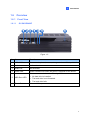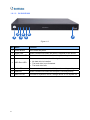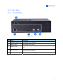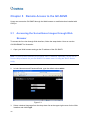
1
GV-SNVR System User’s Manual SNVR-UM-A © 2014 GeoVision, Inc. All rights reserved. Under the copyright laws, this manual may not be copied, in whole or in part, without the written consent of GeoVision. Every effort has been made to ensure that the information in this manual is accurate. GeoVision, Inc. makes no expressed or implied warranty of any kind and assumes no responsibility for errors or omissions. No liability is assumed for incidental or consequential damages arising from the use of the information or products contained herein. Features and specifications are subject to change without notice. GeoVision, Inc. 9F, No. 246, Sec. 1, Neihu Rd., Neihu District, Taipei, Taiwan Tel: +886-2-8797-8377 Fax: +886-2-8797-8335 http://www.geovision.com.tw Trademarks used in this manual: GeoVision, the GeoVision logo and GV series products are trademarks of GeoVision, Inc. Windows and Windows XP are registered trademarks of Microsoft Corporation. Ocotober 2014 Contents Chapter 1 Introduction ...........................................................................................1 1.1 Feature ..................................................................................................................... 2 1.2 Model……. ................................................................................................................ 2 1.3 Packing List............................................................................................................... 3 1.4 1.3.1 GV-SNVR Package....................................................................................... 3 1.3.2 Bundled Package for GV-SNVR0400F ......................................................... 4 Compatible Devices and System Requirements....................................................... 5 1.4.1 Supported GV-IP Cameras ........................................................................... 5 1.4.2 System Requirement .................................................................................... 6 1.5 Options ..................................................................................................................... 6 1.6 Overview ................................................................................................................... 7 1.6.1 Front View..................................................................................................... 7 1.6.2 Rear View ..................................................................................................... 9 Chapter 2 Getting Started .................................................................................... 11 2.1 Installing the Hard Drive..........................................................................................11 2.1.1 GV-SNVR0400F...........................................................................................11 2.1.2 GV-SNVR1600............................................................................................ 13 2.2 Interface Connections ............................................................................................ 15 2.2.1 Network Connection for GV-SNVR1600 ..................................................... 16 2.3 Initial Configuration ................................................................................................ 17 2.3.1 Automatically setting up GV-IP Camera...................................................... 17 2.3.2 Manually Connecting GV-IP Camera .......................................................... 19 2.3.3 Changing Cameras and Assigning Channels ............................................. 20 2.4 Formatting the Hard Drive...................................................................................... 21 2.5 Main Screen........................................................................................................... 23 2.6 Enabling the Recording.......................................................................................... 24 2.7 Playing Back Video ................................................................................................ 24 2.8 Live Monitoring....................................................................................................... 25 2.8.1 Snapshot..................................................................................................... 25 2.8.2 Audio........................................................................................................... 26 2.8.3 PTZ Control................................................................................................. 27 Chapter 3 System Configuration .........................................................................29 3.1 Camera .................................................................................................................. 29 3.2 Recording............................................................................................................... 31 3.3 Network.................................................................................................................. 32 i 3.4 Storage................................................................................................................... 35 3.5 System ................................................................................................................... 36 Chapter 4 Video Playback ....................................................................................39 4.1 Timeline Player ...................................................................................................... 39 4.2 Recording Backup.................................................................................................. 41 Chapter 5 Remote Access to the GV-SNVR........................................................42 5.1 Accessing the Surveillance Images through Web Browser.................................... 42 5.1.1 Live View Screen ........................................................................................ 44 5.1.2 Snapshot of Live Video ............................................................................... 46 5.1.3 Picture-in-Picture View................................................................................ 47 5.1.4 Picture-and-Picture View ............................................................................ 48 5.1.5 Digital PTZ Control...................................................................................... 49 5.2 Accessing the Surveillance Images through Smart Device ................................... 50 Chapter 6 Advanced Applications.......................................................................51 6.1 Upgrade of System Firmware ................................................................................ 51 6.2 Using the GV-IP Device Utility ............................................................................... 52 6.2.1 Looking up the IP Address .......................................................................... 52 6.2.2 Accessing the Live View ............................................................................. 52 6.2.3 Upgrading System Firmware ...................................................................... 53 6.2.4 Backing up and Restoring Settings............................................................. 54 Specifications ..........................................................................................................56 Appendix………. ......................................................................................................58 ii A Tested and Supported Hard Disk Drives................................................................ 58 B Live View Streaming .............................................................................................. 59 1 Chapter 1 Introduction Introduction The GV-SNVR0400F / GV-SNVR1600 is a Linux-embedded Standalone Network Video Recorder which records video files directly to the internal hard drive, supporting up to 4 / 16 channels of GV-IP Cameras for network surveillance. With the feature of a Full HD HDMI video output, the GV-SNVR eliminates the need for a separate PC to view and play back video from the unit. Its four / five USB ports allow you to connect a storage device to import or export system settings, update firmware, save snapshot files and back up video in AVI format. Optionally, you can connect a GV-Joystick V2 to control PTZ cameras. Moreover, you can remotely access the live view through mobile devices or Web browsers with advanced video features. Figure 1-1 1 1.1 Features ˙ 4-Channel video recording (for GV-SNVR0400F) ˙ 16-Channel video recording (for GV-SNVR1600) ˙ Automatic search and set-up for IP cameras ˙ Dual streams support ˙ Continuous, motion and scheduled recordings ˙ Timeline playback ˙ Multi-channel playback ˙ Display of HDD status and system temperature ˙ DST (Daylight Saving Time) support ˙ NTP (Network Time Protocol) support ˙ GeoVision DDNS server support ˙ E-mail notification for recording error and password retrieval ˙ Recording export ˙ Remote live view through Web browser ˙ PTZ control using GV-Joystick V2 or on-screen panel ˙ 1080p HDMI video output ˙ 1 SATA HDD drawer (3.5”) for up to 4 TB storage (for GV-SNVR0400F) ˙ 4 SATA HDD drawer (3.5”) for up to 16 TB storage (for GV-SNVR1600) ˙ Smart device access (iOS and Android) ˙ Support for 9 languages 1.2 Models The GV-SNVR has the following models: GV-SNVR0400F GV-SNVR1600 2 - Supports 1 SATA HDD (3.5”) - Records up to 4 IP channels - Supports 4 SATA HDD (3.5”) - Records up to 16 IP channels 1 Introduction 1.3 Packing List You can choose to purchase a GV-SNVR package or a bundled package which includes 4 GV-Target IP Camera of your choice and a GV-PoE switch. 1.3.1 GV-SNVR Package GV-SNVR0400F 1. GV-SNVR0400F 2. AC power cord 3. AC/DC adapter (DC 19V, 3.42A, 65 W) 4. Screw x 6 (for HDD) 5. SATA cable GV-SNVR1600 1. GV-SNVR1600 2. AC power cord 3. SATA cable x 4 4. HDD Mounting Bracket Kit (4 pairs and 32 screws included) 5. Rack Mount Kit (2 L-shaped brackets and 6 screws included) 3 1.3.2 Bundled Package for GV-SNVR0400F 1. GV-SNVR0400F Package x 1 2. Target IP Camera x 4 3. GV-POE0400 x 1 Note: For the Target IP Camera, select any 4 models from GV-EBL1100 / 2100, GV-EBX1100 / 2100, GV-EDR1100 / 2100, GV-EFD1100 / 2100. For more information, contact our sales representatives. 4 1 Introduction 1.4 Compatible Devices and System Requirements 1.4.1 Supported GV-IP Cameras The GV-SNVR0400F / 1600 is compatible with the following GV-IP Cameras: ˙ GV-Target Series IP Camera (Firmware V1.0 or later) ˙ GV-SD220/220-S (Firmware V1.02 or later) ˙ All the other GV-IP Cameras (Firmware V2.11 or later) EXCEPT the models below: GV-BX110 GV-BL110 GV-Fisheye IP Camera GV-MFD110 GV-PT110 GV-PTZ010D GV-SD010/200/200-S IMPORTANT: 1. The GV-SNVR supports the recording frame rate of up to 30 fps only. 2. The GV-SNVR supports the recording bandwidth of up to 50 /100 Mbps only for GV-SNVR0400F / GV-SNVR1600 respectively. 5 1.4.2 System Requirements Recommended Hard Disks GV-SNVR0400F supports 1 SATA HDD (3.5”) with up to 4 TB capacities, and GV-SNVR1600 supports 4 SATA HDD (3.5”) with total up to 16 TB capacities. For system efficiency, it is recommended to use the enterprise-level hard disk drives instead of desktop-level or green HDD. For tested hard disk drives, see Appendix. Note: The GV-SNVR does not support the 2.5” SATA HDD. Supported Web Browsers Internet Explorer 8 or later Google Chrome 33.0 or later Mozilla Firefox 28.0 or later 1.5 Options Optional devices can expand your GV-SNVR’s capabilities and versatility. Contact your dealer for more information. The GV-Joystick V2 facilitates the PTZ camera control. It can be GV-Joystick V2 plugged into the GV-SNVR for independent use to empower the operation of PTZ cameras. The GV-POE Switch is designed to provide power along with GV-POE Switch network connection for IP devices. The GV-POE Switch is available in various models with different numbers and types of ports. Slide Rail Kit 6 The Slide Rail Kit is used to mount a rail for the GV-SNVR1600 in a 19” cabinet. 1 Introduction 1.6 Overview 1.6.1 1.6.1.1 Front View GV-SNVR0400F Figure 1-2 No. Name Function 1 USB 2.0 Port Connects to keyboard, mouse, storage device or GV-Joystick V2. 2 Audio In Not functional. 3 Audio Out Not functional. 4 Power LED Shows constant blue when the power is supplied for the device. Shows constant red when the following situations occur: 5 HDD Error LED ˙ No hard drive is installed. ˙ The hard drive is not formatted. ˙ The hard drive fails. 6 Power Button Turns on/off the power. 7 1.6.1.2 GV-SNVR1600 Figure 1-3 No. Name Function 1 Power Button Turns on/off the power. 2 Power LED Shows constant blue when the power is supplied for the device. 3 HDD Status LED Glows blue when the hard drive is writing or reading data. Shows constant red when the following situations occur: 4 HDD Error LED ˙ No hard drive is installed. ˙ The hard drive is not formatted. ˙ The hard drive fails. 8 5 WAN LED Shows constant blue when the WAN port is receiving activity. 6 LAN LED Shows constant blue when the LAN port is receiving activity. 7 USB 2.0 Port Connects to keyboard, mouse, storage device or GV-Joystick V2. 1 1.6.2 Introduction Rear View 1.6.2.1 GV-SNVR0400F Figure 1-4 No. Name Function 1 Gigabit Ethernet Port Connects to the network. 2 HDMI Output Connects to the HD TV. 3 USB 2.0 Port Connects to keyboard, mouse, storage device or GV-Joystick V2. 4 Default Button Restores the device to default settings. Press the button for 15 seconds to load default. 5 Power Input Connects to power supply. 9 1.6.2.2 GV-SNVR1600 Figure 1-5 No. Name Function 1 Audio Microphone In Port Not functional. 2 VGA Monitor Output Connects to the VGA monitor. 3 HDMI Port Connects to the HD TV. 4 USB 2.0 Port x 4 Connects to keyboard, mouse, storage device or GV-Joystick V2. 5 Power Input Connects to power supply. 6 Gigabit Ethernet Port (LAN) Connects to the network. 7 Gigabit Ethernet Port (WAN) Connects to the network. 8 Audio Line Out Port Connects to the speaker. 9 Audio Line Out Port Connects to the headphone. Note: When the two Ethernet ports (No. 6 and No. 7) are used together, one is LAN port and the other is WAN port. 10 2 Chapter 2 2.1 Getting Started Getting Started Installing the Hard Drive The GV-SNVR uses SATA hard drive for video data storage. Before recording, be sure to install the hard drive. 2.1.1 GV-SNVR0400F Follow the steps below to install the hard drive to the GV-SNVR0400F. 1. Unscrew the two screws on the rear panel and remove the cover. Figure 2-1 2. Unscrew the drive drawer and take it out from the device. Figure 2-2 11 3. Place the hard drive in the drive drawer as below by aligning the three holes. Figure 2-3 4. Secure the hard drive with the drive drawer using the supplied 6 screws (3 screws on each side). Figure 2-4 5. Connect the SATA Power Cable and Data Cable to the hard drive. Figure 2-5 6. Put the drive drawer back in the device and secure the two screws on the drive drawer (Figure 2-2). 7. Assemble the cover with the device by tightening the screws on rear panel (Figure 2-2). The hard drive is now ready to use. 12 2 2.1.2 Getting Started GV-SNVR1600 Follow the steps below to install the hard drive to the GV-SNVR1600. 1. Loosen the 6 screws and remove the cover. Figure 2-6 2. Assemble the mounting brackets with the hard drive and tighten the screws on both sides. Figure 2-7 Note: Each mounting bracket is labeled L or R for recognition. Align the mounting bracket with the holes on the hard drive and make sure it is secured to the correct side. 3. Align the mounting bracket with the holes inside the unit. Figure 2-8 13 4. Tighten the 4 screws on the side of the hard drive. Figure 2-9 5. Connect the SATA Power Cable and Data Cable to the hard drive. Figure 2-10 6. To install more HDDs, repeat the steps above. 7. Place the cover back and tighten the screws. The hard drive is now ready for use. 14 2 Getting Started 2.2 Interface Connections Follow the steps below to connect the GV-SNVR. Figure 2-11 1. Connect the GV-SNVR to power. 2. Connect the GV-SNVR to the LAN port using the RJ-45 cable. 3. For GV-SNVR1600, connect speakers to the Audio Line Out port. 4. Connect the HDTV to HDMI connector for video output. For GV-SNVR1600, optionally connect the VGA monitor to the D-Sub connector for dual-monitor display. 5. Connect the mouse and the keyboard to the USB ports. Press the power button to turn on the GV-SNVR. 15 Note: 1. The GV-SNVR is DHCP enabled. When it is connected to the network, it will be automatically assinged an IP address. 2. For GV-SNVR1600, the monitor used for VGA output must be capable of having a screen resolution of 1080p. 2.2.1 Network Connection for GV-SNVR1600 There are two network ports, LAN and WAN, for the GV-SNVR1600. If both network ports are used simultaneously, only the WAN port can be connected to the Internet. Therefore, it is recommended to connect the devices as below. Figure 2-12 1. Connect GV-IP Cameras to the GV-SNVR1600 through the LAN port. 2. Connect GV-SNVR1600 to the Internet through the WAN port. Note: When the LAN and WAN ports are used together, the Auto Search function is only supported by the LAN port. To connect to GV-IP Cameras under the WAN, you can add the cameras manually. IMPORTANT: It is required to divide LAN and WAN networks into different subnets or segments; otherwise, your network will fail. For details, see 3.3 Network. 16 2 Getting Started 2.3 Initial Configuration After you have installed the IP cameras under the same LAN with the GV-SNVR, you are ready to display the channels on GV-SNVR. 2.3.1 Automatically setting up GV-IP Camera To automatically set up the IP cameras, follow the steps below. 1. Power on the GV-SNVR. It automatically searches and lists the IP cameras under the same LAN. 2. You are prompted with a dialog box asking if you want to automatically assign IP address. The automatic assignment will only apply on the cameras with IP address 192.168.0.10. Figure 2-13 3. Click Apply. The GV-SNVR assigns unused IP addresses to the cameras in an ascending numerical order and enables the connection. Figure 2-14 Upon successful connection, the status displays “Connected”, with the resolution and bandwidth being displayed in the correspondent columns. When you close the Camera page, you can access the live view. 17 IMPORTANT: 1. By default, GV-IP Cameras have the IP address 192.168.0.10. The GV-SNVR will automatically assign unused IP addresses to these cameras to avoid IP address conflict with others under the same LAN. 2. The GV-SNVR connects with IP cameras with the default ID and password admin. If you fail to log in the IP camera, click the Edit icon password for connection. 18 and type the correct ID and 2 2.3.2 Getting Started Manually Connecting GV-IP Camera To manually add the GV-IP Camera to the camera list, follow the steps below. 1. On the Camera page, click the Add Cameras button. 2. Type the IP Address, Username and Password of the desired IP camera. Keep the default Port 10000 or modify if necessary. Figure 2-15 3. Click Apply to add the IP camera. 4. To add multiple cameras, repeat step 2, type the number of cameras you want to create in the Add Camera column. ˙ To duplicate camera with same IP address but different ports, type the IP address and click the Duplicate column of Port. ˙ To duplicate camera with same port number but different IP addresses, type the port number and click the Duplicate column of IP Address. 5. To connect the GV-SNVR with the added cameras, click the box next to the CH column on the Camera page. Figure 2-16 6. To delete the added IP camera, click the Delete button Camera page. of the camera on the 19 2.3.3 Changing Cameras and Assigning Channels On the Camera page, you can change the connected IP cameras and re-assign the channels for display. For example, to change the camera on Channel 1, deselect the connected camera on Channel 1 and select another camera for connection. The selected camera is now assigned to Channel 1. Figure 2-17 20 2 Getting Started 2.4 Formatting the Hard Drive After installing the hard drive to GV-SNVR, you need to format the hard drive before enabling the monitoring. 1. On the main screen, click the Setting button. Figure 2-18 2. Select Storage. Figure 2-19 3. Click Format. This dialog box appears. Figure 2-20 4. Click Execute to format the hard drive. 21 When the hard drive is successfully formatted, its icon should be marked with a green tick, and the “Normal” message appears. The information of operating temperature, hard drive status and total time in use is also displayed. Figure 2-21 Note: When the hard drive status displays other value instead of 0, replace the hard drive with a new one to ensure proper video recording. 22 2 Getting Started 2.5 Main Screen Close the Camera page to display connected channels on the main screen. Here we use GV-SNVR0400F for illustration. 1 10 9 8 6 7 5 2 4 3 Figure 2-22 No. Name 1 Camera Name 2 System 3 Setting 4 Record 5 Description Indicates the camera name. The column changes from gray to red when the recording is enabled. See Camera Name in 3.1 Camera. Brings up the options: Log Out and Shutdown. Accesses the settings of Camera, Recording, Network, Storage and System. Starts/Stops monitoring. Division & Page Selects screen divisions and switch between cameras in single Up / Down division. 6 Playback Displays the playback panel. 7 Date / Time Displays the current date and time. 8 Device Name 9 Temperature 10 Model Name Displays the device name of GV-SNVR. See Device Name in 3.5 System. Displays the current temperature. Displays the model name of GV-SNVR. 23 2.6 Enabling the Recording To start recording, click the Record button (No. 4, Figure 2-22) and select a camera. To enable recording for all the connected cameras, select Start All Monitoring. By default, the GV-SNVR records with the Round-the-clock mode and H.264 codec. The default recording resolution depends on the settings of each camera. ˙ To change recording mode, see 3.2 Recording. ˙ To change video resolution, see 3.1 Camera. 2.7 Playing Back Video You can instantly play back the recorded video without interrupting the monitoring and recording. ˙ To instantly play back the recording of one single channel, click the Camera Name (No. 1, Figure 2-22), select Instant Playback. ˙ To instantly play back the recording of all channels, click the Playback button (No. 6, Figure 2-22). Note: For details on playing back the recording, see Chapter 4 Video Playback. 24 2 Getting Started 2.8 Live Monitoring GV-SNVR0400F On the main screen, the live view of connected cameras is displayed in 4 divisions by default. You can click the Division button (No. 5, Figure 2-22) and select 1 or 4 Division. Optionally, click on the live view of desired camera to switch to full screen. Figure 2-23 GV-SNVR1600 On the main screen, the live view of connected cameras is displayed in 16 divisions by default. You can click the Division button and select 1, 4 or 9 Division. Optionally, click on the live view of desired camera to switch to full screen. Figure 2-24 2.8.1 Snapshot To take a snapshot of live or playback video, follow the steps below. 1. Connect an USB storage device of FAT32 format to the GV-SNVR. 2. Click the camera name of desired camera and select Snapshot. The message “Snapshot Success” pops up when the captured image is successfully saved to the USB storage device. Each image is automatically saved in JPEG format with a file name indicating the date and time of snapshot. 25 2.8.2 Audio To enable the audio function on live video, follow the steps below. Note: 1. The audio function is only available for GV-SNVR1600. 2. To listen to the audio, make sure the Enable Audio function is applied for the camera. For details, see 3.1 Camera. 1. Click the live view of the desired camera to switch to full screen. 2. Click the camera name and select Speaker. The audio icon camera name, and the audio is now accessible. Figure 2-25 26 appears beside the 2 2.8.3 Getting Started PTZ Control To enable the PTZ function on live video, click the camera name of desired camera and select Enable PTZ. The PTZ control panel appears at the lower-right corner of the live view. Note: The option is only available for the cameras supporting PTZ functions. Figure 2-26 Figure 2-27 Home: Brings the PTZ live view back to the Home position. Pan/Tilt Control: Allows the camera to pan and tilt to any angle. Zoom Control: Allows the camera to zoom in or out. Focus Control: Adjusts the camera to focus in or out. Preset Option: Moves the camera to a preset point by entering a preset number using the onscreen keypad. To enable PTZ control, you can also use the GV-Joystick V2, a plug-and-play device used to pan, tilt, zoom and focus a PTZ camera. When the GV-Joystick V2 is connected to the USB port on the GV-SNVR, the Joystick icon will appear beside the camera name. Figure 2-28 27 For details on the GV-Joystick V2, see GV-Joystick V2 User’s Manual. Note: The GV-SNVR does not support GV-Keyboard. Digital PTZ Function For non-PTZ cameras, the Digital PTZ (DPTZ) function allows you to simulate the PTZ movement on the screen. Note: The DPTZ function is only available for GV-SNVR1600. To enable the DPTZ function on live video, click the camera name of desired camera and select Enable Digital PTZ. The PTZ control panel appears at the lower-right corner of the live view. Click the Zoom In button first and then click Tilt and Pan buttons to move the camera view. Figure 2-29 Figure 2-30 Home: Brings the DPTZ live view back to the Home position. Pan/Tilt Control: Allows you to pan and tilt on the live view. Zoom Control: Allows you to zoom in or out on the live view. Note: 1. The Focus Control and Preset functions are not supported. 2. The DPTZ function is only available for non-PTZ cameras. 28 3 Chapter 3 System Configuration System Configuration This section introduces the settings of camera, video recording, network, storage and system. 3.1 Camera To access the camera settings, click the Edit button page. of desired camera on the Camera Figure 3-1 The Camera Settings page appears. Figure 3-2 29 Camera Name: Type a desired name for the camera. Username: Type the username of the camera. The default is admin. Password: Type the password of the camera. The default is admin. Enable Audio: Click to enable audio streaming. Note this function is only available for GV-SNVR1600. Motion Area: Draw up to 8 areas with different sensitivity values on the image for motion detection. Motion Sensitivity: Configure the sensitivity value from 1 to 10 for the motion detection. The higher the value, the more sensitive the camera is to the motion. Codec: The video codec is H.264. Resolution: Select the video resolution for the camera. FPS: Set up recording frame rate for the camera. Note the GV-SNVR0400F / 1600 supports up to 30 fps. Quality: Select the level of video quality. Max. Bit Rate: Set up the maximum bit rate of video stream. Image Orientation: Adjust the image orientation by selecting Normal, Horizontal Mirror, Vertical Flip or Rotate 180. To enable the settings, click Apply. 30 3 3.2 System Configuration Recording You can set up desired recording mode for specific period on specific days for each connected camera. The default recording mode is round-the-clock. Figure 3-3 1. Select a camera from the drop-down list at the upper-right corner. 2. To set up the recording mode, click the Motion Recording icon Round-the-clock icon or and drag the cursor on the desired period. 3. To clear the settings, click the Clear icon and drag the cursor on the desired period. 4. Click Apply or Apply to all cameras as desired to enable the settings. 31 3.3 Network The Network section includes basic network configurations that enable the GV-SNVR to be connected to the network. By default, the GV-SNVR is assigned with a dynamic IP address when connecting to the network. [LAN] Figure 3-4 IP Configuration: Select DHCP or Static according to your network environment. MAC Address: Displays the MAC Address of the GV-SNVR. To assign a static IP address, select Static and fill out the required settings below. IP Address: Type a static IP address for the GV-SNVR. The default is 192.168.0.100. Subnet Mask: Type a subnet mask. The default is 255.255.255.0. Gateway: Type a gateway. The default is 192.168.0.1. Primary DNS: Type a primary DNS. The default is 192.168.0.1. Second DNS: Type a second DNS. The default is 192.168.0.2. Click Apply. The GV-SNVR is now accessible by entering the assigned IP address on Web browser. 32 3 System Configuration [WAN] Figure 3-5 IP Configuration: Select DHCP or Static according to your network environment. MAC Address: Displays the MAC Address of the GV-SNVR. To enable the PPPoE connection, select PPPoE and fill out the required settings below. Primary DNS: Type a primary DNS. The default is 192.168.100.1. Second DNS: Type a second DNS. The default is 192.168.100.2. PPPoE Username: Type the username you have registered for PPPoE. PPPoE Password: Type the password you have registered for PPPoE. Note: The WAN configuration is only available for GV-SNVR1600. IMPORTANT: When the LAN and WAN are applied simultaneously, note the following: Only the WAN can be connected to the Internet. Only the IP Cameras under the same LAN can be searched by the GV-SNVR1600. To connect with the IP cameras under the WAN, you must add the cameras manually. For details, see 2.3.2 Manually Connecting GV-IP Camera. 33 [DDNS] DDNS (Dynamic Domain Name System) provides a convenient way of accessing the GV-SNVR when using a dynamic IP address. DDNS assigns a domain name to the GV-SNVR, so you do not need to go through the trouble of checking if the IP address assigned by DHCP Server or ISP (in xDSL connection) has changed. Before enabling the following DDNS function, you should have applied for a Host Name from the DDNS service provider’s website. The provider is GeoVision DDNS Server, http://ns.gvdip.com/register.aspx. Figure 3-5 To enable the DDNS function, click the Enable box, type the hostname and password you have registered with GeoVision DDNS Server and click Apply. 34 3 System Configuration [E-mail] Configure your mail server to allow e-mail notification on: ˙ Recording error of writing recording data to the hard disk drive ˙ Request for retrieving the username and password for system login Figure 3-6 Sender: Type the sender’s e-mail address. Receiver: Type the recipients’ e-mail address. SMTP Sever: Type your mail server’s URL address or IP address. SMTP Port: Type your mail server’s port value. Authentication: Select Enable if the SMTP Server needs authentication and type a valid username and password to log in the SMTP server in the next two columns. Select Enable SSL if your e-mail server requires the SSL authentication for connection. 3.4 Storage You must format the hard drive before enabling the video recording. For details, see Formatting the Hard Drive in Chapter 2. 35 3.5 System On the System page, you can access the configuration of login information of Administrator and Guest, video resolution and time settings. You can also access the system log with filter as desired. Figure 3-7 [System] Device Name: Type a desired name for the GV-SNVR. Language: Select English, Traditional Chinese, Spanish, Russian, Portuguese, French, German, Italian or Japanese as the language of the OSD interface. Administrator Account: Type the username of the Administrator. The default is admin. Administrator Password: Type the password of the Administrator. The default is admin. Guest Account: Type the username of the Guest. The default is guest. Guest Password: Type the password of the Guest. The default is guest. Auto Login: Select Enable to automatically log in the GV-SNVR at startup. Default Camera Account: Set up the default username of camera for connection. The default is admin. 36 3 System Configuration Default Camera Password: Set up the default password of camera for connection. The default is admin. Temperature: Select a temperature scale for the display of operating temperature. Resolution: Select the video output resolution from 720p, 1080p and 1080i. Note: The Resolution options are not available for GV-SNVR1600, which only supports the resolution of 1080p. To restore the GV-SNVR to default settings, click Load Default and follow the on-screen instructions. Optionally, press the Load Default button on the rear panel of the device for 15 seconds. To import or export the system settings and update firmware, click Advanced Options for configuration. Optionally, you can configure through the GV-IP Device Utility. For details, see 6.2 Using the GV-IP Device Utility. [Time] Figure 3-8 Time Zone: Select a time zone of your location. Daylight Saving Time: Click Enable and type the start time and end time for the system to automatically adjust to Daylight Saving Time. Time Sync: Click Enable NTP and type the URL of a network time server to synchronize the clock of GV-SNVR over network. Otherwise, manually set up the date and time by filling out the correspondent fields. 37 Date Format Setup: Select a desired format for date display. To enable the settings, click Apply. Note: You can also use the GV-IP Device Utility to synchronize the date and time of GV-SNVR with a computer. For details, see GV-IP Device Utility Installation Guide on the Software CD. [System Log] This page lists all the changes made to the system. Figure 3-9 To search for the changes made at specific time, click the Filter button upper-right corner to access the following options for event filtering. Time: Set up the desired time period. Device: Select a channel. Type: Select User or System. Event: Select the desired type of event. 38 at the 4 Chapter 4 Video Playback Video Playback The timeline player plays back recorded video without affecting recording. There are two ways to launch the timeline player: ˙ On the main screen, click the Playback button (No. 6, Figure 2-15). ˙ On the camera live view, click the desired camera name and select Instant Playback. On the timeline player screen, the system automatically plays back video recording from 3 minutes before the playback function is enabled. 4.1 Timeline Player Without further settings you can play back the video recording by selecting desired time period and clicking the Play button on Playback Panel. To switch the current view mode, click the Division button. Here we use GV-SNVR0400F for illustration. Figure 4-1 39 The controls in the timeline player screen: No. Name Description 1 Camera Name Indicates the camera name. 2 Camera View Displays the playback video. 3 Date Display Allows you to specify a date to play back the recorded video. The date with video recording is highlighted in blue. 4 Timeline Consists of 48 grids, with each specifying half an hour. The time period with video recording is highlighted in blue. 5 Playback Panel Contains typical playback control buttons. 6 Live Closes the timeline player and returns to live view window. 7 Division For GV-SNVR0400F, switches between 1-channel and 4-channel view; for GV-SNVR1600, switches between 1-channel, 4-channel, 9-channel and 16-channel view. 8 Export Exports the video recording as AVI files to an external hard drive. Use controls on Playback Panel to view the event in the way you want. Move the Slider forward or backward to navigate video frames. Slow Next Previous Frame Step Play / Pause Next Step Fast Speed Playback Slider Time of the Video Figure 4-2 40 4 4.2 Video Playback Recording Backup Using the timeline player, you can back up recordings to the external hard drive. To back up recordings, follow the steps below. 1. Connect an external hard drive of FAT32 format to the USB port on the unit. 2. On the timeline player screen, click Export (No.8, Figure 4-1). 3. Select the desired date and time period of video recording. 4. Select the channel of desired camera and click Export. The video recording is exported to the external hard drive. The backup recordings are in AVI format. To play back the recordings using Windows Media Player, you need to install GeoVision codec in the dedicated PC. Otherwise you can install the GV-ViewLog player for playback. Note: 1. The recording backup only supports video. The audio will not be included in the backup recordings. 2. For backup efficiency, it is suggested to use the external hard drive to back up recordings. 3. If the GV-SNVR is connected with more than one storage device, the video recordings will be backed up to the first storage device connected. 41 Chapter 5 Remote Access to the GV-SNVR Users can access the GV-SNVR through the Web browser or mobile devices installed with GV-Eye. 5.1 Accessing the Surveillance Images through Web Browser To access the live view through Web interface, follow the steps below. Here we use the GV-SNVR0400F for illustration. 1. Open your Web browser and type the IP address of the GV-SNVR. Note: To look up the IP address of GV-SNVR, see 3.3 Network. Optionally, run the GV-IP Device Utility to search for your GV-SNVR. For details, see 6.2 Using the GV-IP Device Utility. 2. In both Username and Password fields, type the default value admin. Figure 5-1 3. Select a desired language from the drop-down list at the upper-right corner for the Web interface and click Login. 42 5 Remote Access to the GV-SNVR 4. To enable the update of live view on your Web browser, you must set the Web browser to allow ActiveX controls and perform a one-time installation of GeoVision’s ActiveX components on your computer. After the installation, live view will be displayed. Note: 1. The maximum number of remote network connection is 10 in total for GV-SNVR0400F and 34 in total for GV-SNVR1600. Every connected channel will be counted as 1 connection. 2. The Web interface supports 9 languages: English, Traditional Chinese, Spanish, Russian, Portuguese, French, German, Italian and Japanese. 3. The audio function is not supported for the live view through the Web interface. 43 5.1.1 Live View Screen After successfully logging in the Web interface, you can access the live view of connected IP cameras. Figure 5-2 No. Name 1 2 44 Description Division & Page Selects screen divisions and switch between cameras in single Up / Down division. Exit Logs out the Web interface. 5 No. Name Remote Access to the GV-SNVR Description Right-click the live view of desired camera to access the functions below. Snapshot: Take a snapshot of live video. For details, see 5.1.2 Snapshot of Live Video. Full Screen: Switch the live view to full screen. 3 Advanced Options Resolution: Display the resolution at the lower-right corner of the live view. Digital PTZ: Simulate the PTZ movement on the screen. For details, See 5.1.5 Digital PTZ Control. PIP: Enable the PIP function. For details, See 5.1.3 Picture-in-Picture View. PAP: Enable the PAP function. For details, See 5.1.4 Picture-and-Picture View. 4 Device Name Recognizes the device name. Note: 1. For all GV-IP Cameras, the Web interface of GV-SNVR0400F / 1600 supports main stream for the display of full screen only. For details, see Appendix B Live View Streaming. 2. The Visual Automation function is not supported. 45 5.1.2 Snapshot of Live Video To take a snapshot of live video, follow the steps below. 1. Right-click on the live view of desired camera and select Snapshot. The Save As dialog box appears. Figure 5-3 2. Select a desired saving path, type the file name and select JPEG or BMP as the Save as Type. 3. In the Preview field, you can choose whether to tag the snapshot with camera name, time and date, select Set Color for the text color and adjust the image quality. 4. Click Save to save the captured image. Note: The resolution of captured image depends on the sub stream of connected camera. 46 5 5.1.3 Remote Access to the GV-SNVR Picture-in-Picture View With the Picture in Picture (PIP) view, you can crop the video to get a close-up view or zoom in on the video. This function is useful for detailed images of the surveillance area. 1. Right-click the desired camera live view and select PIP. An inset window of the camera view appears in the bottom right corner. Figure 5-4 2. Double-click the inset window. A hand icon appears. 3. Click the inset window. A navigation box appears. Figure 5-5 4. Move the navigation box around in the inset window to have a close-up view of the selected area. 5. To adjust the navigation box size, move the cursor to any of the box corners to enlarge or diminish the box. 6. To change the frame color of the navigation box, right-click the image, select Mega Pixel Setting and then Set Color of Focus Area. 7. To exit the PIP view, right-click the camera view and click PIP again. 47 5.1.4 Picture-and-Picture View With the Picture and Picture (PAP) view, you can create a split video effect with multiple close-up views on the image. Up to 7 close-up views can be defined for clear and detailed images of the surveillance area. 1. Click the live view of desired camera and select PAP. A row of three inset windows appears on the bottom of the screen. Figure 5-6 2. Draw a navigation box on the image. This selected area is immediately reflected in one inset window. Up to seven navigation boxes can be drawn on the image. 3. To adjust a navigation box size, move the cursor to any of the box corners to enlarge or diminish the box. 4. To move a navigation box to another area on the image, drag it to that area. 5. To change the frame color of the navigation box, right-click the image, select Mega Pixel Setting and click Set Color of Focus Area. 6. To hide the navigation box on the image, right-click the image, select Mega Pixel Setting and click Display Focus Area of PAP Mode. 7. To delete a navigation box, right-click the desired box, select Focus Area of PAP Mode and select Delete. 8. To exit the PAP view, right-click the camera view and select PAP again. 9. To add another navigation box when less than seven navigation boxes are drawn, right-click the camera view, select PAP to enter, right-click the image, select Mega Pixel Setting and then Enable Add-Focus-Area-Mode. 48 5 5.1.5 Remote Access to the GV-SNVR Digital PTZ Control In non-PTZ cameras, the Digital PTZ (DPTZ) function allows you to simulate the PTZ movement on the screen. This function is also supported in PT / PTZ cameras. Note: The Digital PTZ function is not supported in the 16-division display. 1. Right-click the live view and select Digital PTZ. In the middle of the camera view, the DPTZ control panel appears. Figure 5-7 2. To zoom in or zoom out, click the corresponding buttons or use the mouse scroll. To bring the visual PTZ view back to its default image, click Home. 3. To pan and tilt the visual PTZ view, zoom in on the image first, and then click and hold the arrow. The arrow appears when you place the cursor in one of the eight directions, i.e. up, down, left, right, left up, left down, right up and right down. 4. To adjust the transparency level of the DPTZ control panel, right-click the camera view, find Digital PTZ and select Transparency. Ten levels range from 10% (fully transparent) to 100% (fully opaque). 5. To close the DPTZ control panel, right-click the camera view and select Exit. 49 5.2 Accessing the Surveillance Images through Smart Device To access the live view of GV-SNVR through the iOS or Android devices, you must install your smart devices with GV-Eye. With GV-Eye, you can watch multiple live view in dual streams, enable the Picture in Picture (PIP) function and take snapshots from your mobile device. For details, see GV-Eye Installation Guide. Note: The functions of audio, PTZ control, I/O trigger and remote playback are not supported in the GV-SNVR. 50 6 Chapter 6 6.1 Remote Access to the GV-SNVR Advanced Applications Upgrading System Firmware GeoVision periodically release the updated firmware on the Website. You can upgrade the firmware using an USB storage drive of FAT32 format. To upgrade the firmware, follow the steps below. 1. Download the firmware file to an USB storage drive. 2. Connect the USB drive to the GV-SNVR. 3. On the main screen, click the Setting button and select System. 4. Click the Advanced Option button and select Firmware Upgrade. 5. Find the firmware file and click Apply. This dialog box appears. Figure 6-1 6. Click Execute. The system starts upgrading firmware and automatically reboots after completing the process. After the system reboot, the main screen will be displayed automatically. Note: Optionally you can use the GV-IP Device Utility to upgrade system firmware, especially for multiple GV-SNVR. For details, see the Upgrading System Firmware section in 6.2 Using the GV-IP Device Utility. 51 6.2 Using the GV-IP Device Utility The GV-IP Device Utility detects all the GV-IP Devices in the LAN and allows you to quickly set up the IP address of the device, upgrade firmware and export/import device settings. For details, see GV-IP Device Utility Installation Guide on the Software CD. 6.2.1 Looking up the IP Address You can use the GV-IP Device Utility to look up the IP address of your GV-SNVR and GV-IP Camera. 1. Install the GV-IP Device Utility from the Software DVD. 2. Double-click the GV-IP Device Utility icon created on your desktop. This dialog box appears. Figure 6-2 3. Click the Search button to locate the IP address of the GV-SNVR and GV-IP Camera under the LAN. Click the Name or Mac Address column to sort. 4. Double-click the IP device and select Web Page to access its Web interface. 6.2.2 Accessing the Live View You can use the GV-IP Device Utility for quick access to the live view of IP cameras connected with SNVR. 1. Double-click the GV-SNVR in the list and select Live View. 2. Select a camera and type the username and password of the camera to access the live view. 52 6 6.2.3 Remote Access to the GV-SNVR Upgrading System Firmware You can also use the GV-IP Device Utility to upgrade firmware of multiple GV-SNVR at the same time. Note the computer used to upgrade firmware must be under the same LAN with the GV-SNVR. 1. Double-click the GV-SNVR in the list and select Configure. This dialog box appears. Figure 6-3 2. Click the Firmware Upgrade tab. This page appears. Figure 6-4 53 3. Click the Browse button to locate the firmware file (.img) saved at your local computer. 4. If you like to upgrade all the GV-SNVR in the list, select Upgrade all devices. 5. Type Password, and click Upgrade to start the upgrade. 6.2.4 Backing up and Restoring Settings With the GV-IP Device Utility, you can back up the configurations in the GV-SNVR and restore the backup data to the current GV-SNVR or import it to another one. To back up the settings: 1. Run GV-IP Device Utility and locate the desired GV-SNVR. 2. Double-click the GV-SNVR in the list and select Configure. Figure 6-3 appears. 3. Click the Export Settings tab. This dialog box appears. Figure 6-5 4. Click the Browse button to assign a file path. 5. Type Password, and click the Export Settings button to save the backup file. 54 6 Remote Access to the GV-SNVR To restore the settings: 1. In Figure 6-5, click the Import Settings tab. This dialog box appears. Figure 6-6 2. Click the Browse button to locate the backup file (.dat). 3. Select Upgrade all devices to import the settings into all the GV-SNVR under the same LAN. To import password settings and/or network settings, select Password Settings and/or Network settings. 4. Click the Update Settings button to start restoring. 55 Specifications Hardware Model GV-SNVR0400F GV-SNVR1600 System OS Embedded Linux No. of Drive Bay 1 (3.5” HDD) Input: AC 100 ~ 230V, 50 ~ 60 Hz Power Source Output: DC 19V, 3.42A, Max. 65 W 4 (3.5” HDD) Input: AC 100 ~ 230V, 50 ~ 60 Hz Output: Max. 100 W Mechanical Gigabit 1 port, RJ-45 2 ports, RJ-45 Video Output HDMI HDMI and D-Sub Audio N/A USB 2.0 Front: 2 ports, Rear: 2 ports Front: 1 port, Rear: 4 ports Ethernet Connector 2 stereo jacks for a speaker and a headphone Note: For GV-SNVR1600, when 2 Ethernet ports are used together, one is LAN port and the other is WAN port. 5 LEDs: Power, LAN, WAN, LED Indicator 2 LEDs: Power, HDD Error Operating Temperature 0°C ~ 40°C (32°F ~ 104°F) 0°C ~ 50°C (32°F ~ 122°F) HDD Status, HDD Error 0% ~ 90% RH 0% ~ 80% RH (non-condensing) (non-condensing) 206 x 220 x 65.5 mm 424.6 x 445 x 43.8 mm (8.11 x 8.66 x 2.58”) (16.72 x 17.52 x 1.72”) Net Weight 1.1 kg (2.43 lb) 4.1 kg (9.04 lb) Regulatory FCC , CE , RCM , RoHS compliant Humidity Dimensions (L x W x H) Software Model GV-SNVR0400F GV-SNVR1600 Video and Audio Video Compression H.264 Video Stream Dual streams from H.264 Video Output 720p / 1080i / 1080p (HDMI) 1080p (HDMI / VGA) Display Division 1/4 56 1 / 4 / 9 / 16 Specifications Model GV-SNVR0400F GV-SNVR1600 Audio Compression N/A G.711 Audio Support N/A Yes Two-Way Audio N/A N/A Max. 50 Mbps for 4 Max. 100 Mbps for 16 channels channels Video and Audio Operation Recording Bandwidth Recording Mode Round the clock / Motion Detection / Schedule Recording Pre Recording 1 ~ 10 sec. Post Recording 30 sec. Instant Playback 3 min. Backup Type USB storage device of FAT32 format Note: For backup efficiency, it is suggested to use the external hard drive to back up recordings. Management Language Firmware Upgrade English / Traditional Chinese / Spanish / Russian / Portuguese / French / German / Italian / Japanese Upgrade through OSD or GV-IP Device Utility Network Network Type LAN, WAN, Internet Protocol DHCP, DynDNS, HTTP, NTP, TCP, UDP System Monitoring and Recovery Power Restoration Automatic restart after power outage Monitoring Software Watchdog Remote Monitoring Live View Max. 10 channels Max. 34 channels connection connection Monitoring Environment IE, Chrome, Firefox and mobile devices Smart Device Access GV-Eye for iOS and Android Access from Web Browser Live View, Image Snapshot, Picture in Picture, Picture and Picture, Digital PTZ Note: All specifications are subject to change without notice. 57 Appendix A. Tested and Supported Hard Disk Drives For system efficiency, it is recommended to use the enterprise-level hard disk drives instead of desktop-level or green HDD. The HDD listed below are tested by GeoVision. Model Capacity WD WD4000F9YZ 4 TB WD4000FYYZ 4 TB WD4001FAEX 4 TB WD40EFRX 4 TB WD3000F9YZ 3 TB WD3000FYYZ 3 TB WD30EFRX 3 TB WD30EURS 3 TB WD30EURX 3 TB WD2000F9YZ 2 TB WD2000FYYZ 2 TB WD20EURS 2 TB WD20EZRX 2 TB WD1003FBYZ 1 TB WD10EURX 1 TB Seagate ST4000NC000 4 TB ST4000NM0033 4 TB ST3000NM0033 3 TB ST3000VX000 3 TB ST2000NC000 2 TB ST2000VX000 2 TB ST1000DM003 1 TB ST1000VX000 1 TB 58 Appendix Model Capacity Toshiba MG03ACA400 4 TB DT01ABA300V 3 TB MG03ACA300 3 TB DT01ABA200V 2 TB DT01ACA200 2 TB Hitachi HUA723030ALA640 3 TB HUS724040ALA640 4 TB HUS724020ALA640 2 TB B. Live View Streaming The default streaming for local display, Web browser and smart device access are listed below. Local Webpage GV-Eye 2.0 Screen Display GV-SNVR0400F GV-SNVR1600 1 Division Stream 1 Stream 1 4 Divisions Stream 1 Stream 1 9 Divisions N/A Stream 2 16 Divisions N/A Stream 2 1 Division Stream 1 Stream 1 4 Divisions Stream 2 Stream 2 9 Divisions N/A Stream 2 16 Divisions N/A Stream 2 1 Division Stream 1 Stream 1 6 Divisions Stream 2 Stream 2 59