1
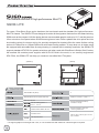
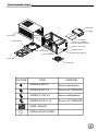
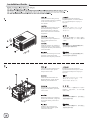
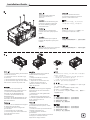
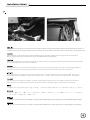
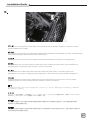
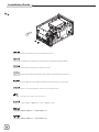
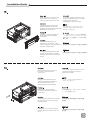
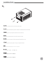
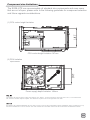
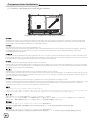
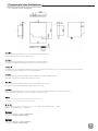
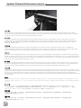
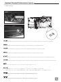
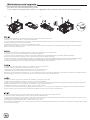
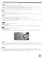
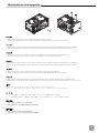
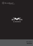
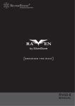
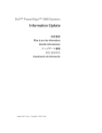
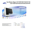
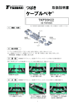
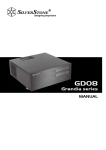
SG08-LITE
The ultimate evolution of high performance Mini-ITX
SG08-LITE
For years, SilverStone Sugo series has been the benchmark and the standard for high-performance
Mini-ITX chassis. The SG08-LITE was designed to retain all the signature features from the award-winning
SG08 such as the compact 14.8-liter design that can accommodate graphic card up to 12.2” and the premium
10mm aluminum front panel where SilverStone engineers have further updated the slim optical slot into
slot-loading variety for cleaner styling. Its specially designed fan bracket offers the users flexible cooling
options for 180mm fan or 120mm/140mm fan with water-cooling radiator. To keep dust out, all intake vents
are equipped with removable filters for easy-cleaning. In contrast with its relatively small size, the SG08-LITE
supports standard ATX PSU for greater selections and when used with SilverStone’s Strider Gold S series,
the smallest full modular power supplies with 80 PLUS Gold in the world, or our carefully engineered
SFX PSUs, the SG08-LITE can help you create an incredible Mini-ITX system.
【FRONT】
【BACK】
SST-SG08B-LITE (black)
2
Extruded aluminum front panel, steel body
USB 3.0 x 2 / audio x 1 / MIC x 1
Mini-DTX, Mini-ITX
Slim slot-loading optical x 1
Support standard ATX PSU up
to 160mm in length
3.5" x 1 , 2.5” x 2
120mm/140mm/180mm fan slot
Support expansion cards up to
12.2” long, width 4.84”*
Oversized vents
VGA exhaust divider
222 mm (W) x 190 mm (H) x 351 mm
(D), 14.8 liters
* To support graphics card longer than 7.25”, a non-modular PSU with maximum 140mm length is required.
Disassemble chart
HDD CAGE
3.5” HDD X 1
TOP COVER
EXPANSION
SLOT X 2
2.5”HDD X 2
FAN BRACKET
SLIM SLOT - LOADING
OPTICAL DRIVE (OPTION)
USB 3.0 + SPK + MIC
MINI - ITX (OPTION)
POWER BUTTON
POWER LED & HDD LED
ATX PSU (OPTION)
FAN FILTER
PSU FILTER
PICTURE
ITEM
PURPOSE
SCREW A M2 X 2
Secure optical drive
SCREW B M3 X 4
Secure 2.5" SSD/HDD
SCREW C 632 X 6
Secure motherboard
SCREW D 632 X 10
Secure 3.5" SSD/HDD
WIRE - MOUNT
INSTALLATION GUIDE
Installation Guide
Unscrew screws holding the top
cover and then remove it by pulling
to the rear and away from
the chassis.
Выкрутите крепежные винты
верхней крышки, а затем снимите
ее, потянувназад и в сторону от
корпуса.
Lösen Sie die Schrauben an der
oberen Abdeckung; entfernen
Sie die Abdeckung, indem Sie
diese nach hinten vom Gehäuse
wegziehen
상부커버를 고정하고 있는 나사를
제거한후, 뒤쪽으로 당겨 커버를
제거합니다.
Dévisser les vis arrière
maintenant le capot supérieur et
tirer le capot supérieur vers
l’arrière.
上部カバーを固定しているネジを外し
てから後方に引き、ケースから取り外
します。
Quite los tornillos que sujetan la
cubierta superior y luego quítela
empujando hacia la parte trasera y
fuera del chasis
請以螺絲起子將上蓋鎖固的螺絲卸下,
並向後拉起自機殼中取出
Svitare le viti che tengono il cover
superiore e quindi rimoverlo
tirandolo verso la parte posteriore.
请以螺丝起子将上盖锁固的螺丝卸下,
并向后拉起自机壳中取出
Unscrew screws holding the fan
bracket and then pull up and
away from the case.
Выкрутите крепежные винты
кронштейна вентилятора, а затем
потяните его вверх и всторону от
корпуса.
Lösen Sie die Schrauben der
Kühlerhalterung; ziehen Sie die
Halterung vom Gehäuse ab
팬 브라켓을 고정하고 있는 나사를
제거한 후, 위로 당겨 올려
케이스로부터 제거합니다.
Dévisser les vis maintenant le
support de ventilateur, puis tirez
vers le haut.
ファンブラケットを固定しているネジ
をはずし、引き上げて、ケースから取
り外します。
Quite los tornillos que sujetan el
bracket del ventilador y luego tire
de él hacia arriba y fuera de la
carcasa.
將鎖固風扇架的螺絲卸下,並向前往上
拉起自機殼中取出
Svitare le viti che tengono il
supporto della ventola, quindi
rimuoverlo dal case.
将锁固风扇架的螺丝卸下,并向前往上
拉起自机壳中取出
Installation Guide
① Unscrew screws holding the hard drive
bracket to remove it.
② Loosen the screw on the PSU cage
to remove it.
③ Secure the PSU onto the PSU cage.
④ Secure the PSU cage onto the chassis
with screws. Connect the power cord.
Unscrew screws holding the
optical drive bracket to
remove it.
Выкрутите крепежные винты
кронштейна привода оптических
дисков, чтобы извлечь его.
Entfernen Sie die Abdeckung des
optischen Laufwerks, indem Sie
die in der Abbildung gezeigten
Schrauben lösen.
광드라이브 브라켓을 고정하고 있는
나사를 풀어 브라켓을 제거합니다
Dévisser les vis maintenant le
support de lecteur optique puis le
retirer.
光学ドライブブラケットを固定してい
るネジを外して取り外します。
Quite los tornillos que sujetan el
bracket del dispositivo óptico para
retirarlo.
將鎖固光碟架的螺絲卸下,並移除光碟架
Svitare le viti che tengono il supporto
del drive ottico per rimuoverlo.
将锁固光盘架的螺丝卸下,并移除光盘架
① Quite los tornillos que sujetan el
bracket del disco duro para
sacarlo.
② Afloje el tornillo de la carcasa
de la FA para retirarla.
③ Fije la FA a la carcasa de la FA.
④ Fije la carcasa de la FA al
chasis con tornillos. Conecte el
cable de potencia.
① Lösen Sie die Schrauben der
Festplattenhalterung; entfernen Sie sie.
② Lösen Sie zum Abnehmen die
Schraube an der Netzteilhalterung.
③ Fixieren Sie das Netzteil an der
Netzteilhalterung.
④ Fixieren Sie die Netzteilhalterung mit
Schrauben am Gehäuse.Schließen Sie
das Stromkabel an.
① Per rimuovere il supporto deglihard
disk svitare le viti che lo assicurano
alla struttura.
② Allentare la vite sulla gabbia PSU
per rimuoverlo.
③ Fissare il PSU sulla gabbia PSU.
④ Fissare la gabbia PSU al telaio con
le viti. Collegare il cavo di
alimentazione.
① Dévisser les vis maintenant le support
de disque dur puis le retirer.
② Desserrez la vis sur la cage PSU
pour la retirer.
③ Fixez le PSU sur la cage PSU
④ Fixez la cage PSU sur la masse avec
les vis. Branchez le cordon
d’alimentation.
① Выкрутите крепежные винты
кронштейна жесткого диска, чтобы
извлечь его.
② Отвинтите винт кронштейна блока
питания и извлеките его.
③ Закрепите блок питания в
кронштейне.
④ Закрепите кронштейн блока питания
на корпусе с помощью винтов.
Подключите шнур питания
① 하드드라이브 브라켓을 고정하고 있는 나사를 풀어
브라켓을 제거합니다.
② PSU 케이스의 나사를 풀어 케이스를 분리합니다.
③ PSU를 PSU 케이스에 고정합니다.
④ 나사를 사용하여 PSU 케이스를 섀시에
고정합니다. 전원 코드를 연결합니다.
① ハードドライブブラケットを固定しているネジを外
して、取り外します。
② PSUケージのネジを緩めて取り外します。
③ PSUケージへPSUを固定します。
④ ケースにPSUケージをネジで固定します。 電源コー
ドを接続します。
①
②
③
④
將鎖固硬碟架的螺絲卸下,並移除硬碟架
將鎖固電源架的螺絲卸下,並移除電源架
將電源安裝上電源架
裝回機殼,接上電源接線
①
②
③
④
将锁固硬盘架的螺丝卸下,并移除硬盘架
将锁固电源架的螺丝卸下,并移除电源架
将电源安装上电源架
装回机壳,接上电源接线
Installation Guide
Insert the I/O shield included
with your motherboard and then
install the motherboard into
the case.
Установите экранированную
панель ввода/вывода системной
платы, а затем установите саму
системную плату.
Setzen Sie das mit Ihrem
Motherboard gelieferte I/O-Blech in
die Aussparungen an der Rückseite
des Gehäuses ein, installieren Sie
anschließend das
메인보드 후면 I/O 커버를 설치한 후
메인보드를 설치합니다.
Insérez la plaque d'E/S inclus avec
votre carte mère, puis installez la
carte mère dans le boîtier.
お持ちのマザーボードに付属のI/Oシール
ドを挿入してから、ケースの中にマザーボ
ードを取り付けます。
Inserte el protector de E/S incluido
en su placa base, luego instale la
placa base en la carcasa.
安裝主機板的I/O彈片,安裝主機板
Installare l’I/O shield della scheda
madre e quindi la scheda madre
stessa.
安装主板的I/O弹片,安装主板
Connect ATX 24pin,
EPS 8pin/ATX 4pin connectors,
front panel connectors, and
front I/O connectors to your
motherboard.
Подключите 24-контактные
ATX-разъемы, 8-контактные
EPS-разъемы/4-контактные
ATX-разъемы, разъемы передней
панели, а также передние разъемы
ввода/вывода к системной плате.
Verbinden Sie die 24-poligen
ATX-, 8-poligen EPS- / 4-poligen
ATX-, die Frontblenden- und die
E/A-Frontanschlüsse
mit Ihrem Motherboard.
ATX 24핀, EPS 8핀,/ATX 4핀 커넥터,
전면패널 커넥터와 전면 I/O 커넥터를
메인보드에 연결합니다.
Connecter l’ATX 24 broches, le EPS
8pin/ATX 4pin et les prises
additionnelles à la carte mère.
ATX 24ピン、EPS 8ピン/ATX 4ピンコネ
クタ、フロントパネルコネクタ、および
フロントI/Oコネクタをマザーボードに
接続します。
Enchufe los conectores ATX de 24
pines, EPS 8 pines/ATX 4 pines, del
panel frontal y los conectores
frontales de E/S a la placa base.
此時你可以準備安插ATX24pin
EPS8in/ATX 4pin,機殼附帶的Front
I/O與Front panel controller
Connettere alla scheda madre il
cavo ATX 24pin, ove necessario il
cavo EPS ATX 4pin/8pin, le
connessioni del pannello frontale e
quelle I/O.
此时你可以准备安插ATX24pin
EPS8in/ATX 4pin,机壳附带的Front
I/O与Front panel controller
Installation Guide
We recommend at this point to start thinking about routing the cables cleanly by fastening ATX 24pin and EPS 8pin/ATX 4pin cables on
a bridge next to the power supply bracket. You may need to store excess cables in the area located on the left side of the hard drive cage.
Wir empfehlen, an dieser Stelle eine saubere Kabelführung zu beachten, indem Sie die 24-poligen ATX- und 8-poligen
EPS-/4-poligen ATX-Kabel an einer Brücke neben der Netzteilhalterung befestigen.
Nous recommandons à ce point du montage de commencer à penser à l'agencement des câbles en attachant l'ATX 24 broches
et le 4 pin EPS 8pin/ATX sur le côté l'alimentation.
Le recomendamos que en este momento empiece a pensar sobre enrutar los cables de un modo correcto enganchando los
cables ATX de 24 pines y EPS 8 pines/ATX 4 pines en un puente cerca del bracket de la fuente de alimentación.
Vi raccomandiamo, a questo punto, di iniziare a pensare ad una corretta sistemazione dei cavi. Unite quindi i due cavi di
alimentazione ed assicurateli per mezzo di una fascetta ad un “ponte” posto nei pressi del supporto dell’alimentatore.
В данный момент рекомендуется подумать об аккуратной прокладке кабелей, для этого необходимо закрепить 24-контактные
ATX-кабели и 8-контактные EPS-кабели/4-контактные ATX-кабели на перемычке рядом с кронштейном блока питания.
이지점에서 ATX 24핀 및 EPS 8핀/ATX 4핀 등 케이블을 정리해 파워 서플라이 옆에 있는 정리 브릿지에 고정시킬 것을 권장합니다.
この時点で、電源ブラケット横のブリッジ上にATX 24ピンとEPS 8ピン/ATX 4ピンケーブルを固定することで、ケーブル取り回しを
すっきりさせることを考慮するようお勧めします。
我們建議ATX 24Pin EPS8in/ATX 4pin電源線可以綁在PSU固定架旁的理線凸橋上,多餘的線材部份可以安置在硬碟架左邊的保留空間
我们建议ATX 24Pin EPS8in/ATX 4pin电源线可以绑在PSU固定架旁的理线凸桥上,多余的线材部份可以安置在硬盘架左边的保留空间
Installation Guide
We recommend to route the USB and audio front I/O cables around the front of hard drive cage, there should be sufficient
bridges for fastening the cables.
Wir empfehlen die Führung der USB- und E/A-Audiofrontkabel um die Vorderseite des Festplattenkäfigs; es sollten genügend
Brücken zur Befestigung der Kabel vorhanden sein
La longueur de câble superflu peutêtre dissimulée sur le côté droit de la cage disque dur.
Le recomendamos que enrute los cables USB y el cable frontal de E/S de audio alrededor de la parte frontal de la carcasa del
disco duro, donde hay suficientes bridas como para sujetar los cables.
Vi raccomandiamo di sistemare i cavi del pannello frontale I/O USB ed audio nei pressi della parte frontale della gabbia degli hard
disk, dove sono presenti sufficienti ponti per l’ancoraggio dei cavi stessi.
Рекомендуется прокладывать USB-кабели и аудиокабели к передним разъемам ввода/вывода вокруг верхней части
корзины для жестких дисков, там должно быть достаточно перемычек для крепления кабелей.
USB와 전면 오디오 및 I/O 케이블을 하드 드라이브의 케이지 전면으로 돌려주어 정리를 할 것을 권합니다.
USBおよびフロントオーディオI/Oケーブルは、ハードドライブケージの前面周囲で取り回します。そこにはケーブルを固定する
ための十分な空間があるはずです。
USB與AUDIO我建議硬碟架的前方繞過,前板上應當有足夠的凸橋安置
USB与AUDIO我建议硬盘架的前方绕过,前板上应当有足够的凸桥安置
Installation Guide
Excess front panel connector
cables can be fastened on
the bottom panel of the case.
Излишки кабелей к разъемам
передней панели можно закрепить
на нижней панели корзины.
Die restlichen FrontblendenAnschlusskabel können an der
unteren Blende des Gehäuses
befestigt werden.
불필요하거나 남는 패널커넥터와
케이블은 케이스 하부 패널에
고정하면 됩니다.
L’excès de câble des prises
additionnelles peut-être dissimulé
dans le bas du boitier.
余ったフロントパネルコネクタケー
ブルはケースの底のパネルに固定で
きます。
El exceso de cables conectores del Front Panel controller的多余线材
panel frontal se puede enganchar en 可以安置绑在底板
el panel inferior de la carcasa.
I cavi in eccesso possono essere
assicurati al fondo del case.
Front Panel controller的多余线材
可以安置绑在底板
Install and secure 3.5” and
2.5” hard drives to the hard drive
cage with screws. The SG08-LITE’s
drive cage is compatible with
2.5” hard drives with 9.5mm
thickness or less.
Установите 3,5-дюймовые и
2,5-дюймовые жесткие диски в корзину
и закрепите винтами. Корзина для
жестких дисков SG08-LITE совместима с
2,5-дюймовыми жесткими дисками
толщиной 9,5 мм или менее.
Installieren und befestigen Sie die 3,5- und
2,5-Zoll-Festplatten mit Schrauben am
Festplattenkäfig. Der Festplattenkäfig des
SG08-LITE ist mit 2,5-Zoll-Festplatten mit
einer Dicke von bis zu 9,5 mm kompatibel.
3.5” 및 2.5” 하드디스크를 하드
드라이브 케이지에 나사로 고정하여
설치합니다. SG08-LITE의 드라이브
케이지는 9.5mm 두께의 2.5” 하드
드라이브 와 호환됩니다.
Installer et fixer les disques durs/SSD dans
les cages à l’aide de vis. Les emplacements
2.5 pouces sont compatibles avec les unités
de 9.5mm au maximum.
3.5インチと2.5インチのハードドライブを
ハードドライブケージに取り付け、ネジで
固定します。 SG08-LITEのドライブケージ
は厚さ9.5mm以内の2.5インチのハードドラ
イブと互換性があります。
Instale y fije los discos duros de 3,5” y 2,5” a
la carcasa para discos duros usando tornillos. 把3.5"硬碟與2.5"硬碟安裝上硬碟架
La carcasa de la SG08-LITE es compatible
,並鎖上螺絲。SG08-LITE的2.5"硬碟
con discos duros de 2,5” con un grosor de
僅支援9.5mm標準厚度
9,5mm o menos.
Installare ed assicurare gli hard disk da 3,5” e
da 2,5” alla gabbia con le apposite viti. La
gabbia di SG08-LITE è compatibile con hard
disk da 2,5” con uno spessore massimo di
9.5mm.
把3.5"硬盘与2.5"硬盘安装上硬盘架
,并锁上螺丝。SG08-LITE的2.5"硬盘
仅支持9.5mm标准厚度
Installation Guide
Install and secure the hard drive
cage with screws.
Установите и закрепите корзину
жестких дисков винтами
Installieren und befestigen Sie den
Festplattenkäfig mit Schrauben.
하드 드라이브 케이지를 설치한 후
나사로 고정합니다.
Réinstallez le casier à disques durs
dans le boîtier comme montré.
ハードドライブケージを取り付け、
ネジで固定します。
Instale y fije la carcasa para discos
duros con tornillos.
將硬碟架安裝上機殼,並鎖上螺絲
Installare ed assicurare la gabbia
degli hard disk al case.
將硬碟架安裝上機殼,並鎖上螺絲
In order to create enough space for power supply cables, the
hard drive cage design is moved as far to the right as possible.
So 90 degree angled SATA connector must be used,
regular 180 degree SATA connector will prevent installation of
top cover.
Чтобы создать достаточное пространство для
кабелей от блока питания, конструкция
корзины жестких дисков смещена вправо,
насколько это возможно.
Поэтому необходимо использовать угловой
SATA-разъем (90 градусов), обычный плоский
SATA-разъем (180 градусов) будет мешать
при установке верхней крышки.
Damit die Netzteilkabel genügend Platz haben, wird der
Festplattenkäfig so weit wie möglich an der rechten Seite
angebracht. Da der 90 Grad winkelige SATA-Anschluss genutzt 파워 서플라이 케이블에 충분한 공간을
werden muss, verhindert ein regulärer 180-Grad-SATA확보하기위해 하드 드라이브 케이지는 최대한
Anschluss die Installation der oberen Abdeckung.
오른쪽으로 위치하도록 디자인되어 있습니다.
그러므로, 90도 SATA 커넥터를 사용하여야
하며, 일반적인 180도 SATA 커넥터를 사용할
Dans le but de créer assez d’espace pour les câbles de
경우 상부커버의 설치가 용이하지 않을 수
l’alimentation, il est préférable de positionner la cage HDD le 있습니다.
plus à droite possible. Il est important d’utiliser des câbles
SATA à 90°, les 180 ° pouvant empêcher l’installation du
capot supérieur.
電源ケーブルのために十分なスペースがあるよ
う、ハードドライブケージ設計は可能な限り右
側に移動されています。
Para poder crear espacio suficiente para los cables de la
それで、90度のアングル付きSATAコネクタを使
fuente de alimentación, el diseño de la carcasa para discos う必要があります。通常の180度方向SATAコネク
duros ha sido pensado para que esté lo más posible hacia
タでは上部カバーが取り付けられません。
el lado derecho.
Es por esto que se debe usar un conector SATA en ángulo
de 90 grados, el conector SATA normal de 180 grados
impedirá la instalación de la cubierta superior.
為了給電源線保留足夠的容線空間,硬碟架
是儘量往右靠的,兩顆2.5"硬碟僅能使用90
度的SATA接線,請不要使用180度的SATA接線
Al fine di creare lo spazio sufficiente per la sistemazione dei ,否則會蓋不上
cavi dell’alimentatore, il supporto degli hard disk è stato
spostato il più possibile sulla destra.
Devono quindi essere usati cavi SATA con connettori a 90°, i 为了给电源线保留足够的容线空间,硬盘架
是尽量往右靠的,两颗2.5"硬盘仅能使用90
cavi con connettore standard a 180° impediscono il
度的SATA接线,请不要使用180度的SATA接线
montaggio del cover superiore.
,否则会盖不上
Installation Guide
We recommend connecting all fan or SATA cables to the motherboard now as installation of graphics or expansion card may
prevent installation of these cables.
Wir empfehlen, nun alle Kühler- oder SATA-Kabel am Motherboard anzuschließen, da die Installation der Grafik- oder Erweiterungskarte die Verbindung dieser Kabel erschweren oder verhindern kann.
Nous recommandons de brancher tous les câbles SATA et FAN avant d’installer les cartes filles ou cartes graphiques.
Le recomendamos que conecte ahora todos los cables SATA o de los ventiladores a la placa base, ya que la instalación de
una tarjeta gráfica o de expansión podría impedir la conexión de estos cables.
Vi raccomandiamo di connettere alla scheda madre tutte le alimentazioni delle ventole o i cavi SATA a questo punto
dell’installazione. Il successivo montaggio di schede di espansione, o della scheda video potrebbe impedirne collegamento.
Теперь рекомендуется подключить все кабели вентиляторов и SATA-кабели к системной плате, так как установка
графической карты или платы расширения может помешать установке этих кабелей.
그래픽카드나 다른 확장카드의 설치로 케이블 설치가 용이하지 않을 수 있어 현 상태에서 팬이나 SATA케이블을 메인보드에
모두 연결할 것을 권합니다.
グラフィックまたは拡張カードの装着により、ケーブルがインストールできなくなる可能性を考え、現在すべてのファンまた
はSATAのケーブルをマザーボードと接続するようにお勧めします。
我建議您在安裝顯示卡之前先確定系統風扇的電源接頭與所有需要用的SATA接頭是否已經安裝好,某些主機板配置會導致安
裝好顯示卡之後風扇接線難以接上
我建议您在安装显示适配器之前先确定系统风扇的电源接头与所有需要用的SATA接头是否已经安装好,某些主板配置会导致安装
好显示适配器之后风扇接线难以接上
Installation Guide
Remove expansion slot screws to remove expansion slot covers.
Lösen Sie zum Entfernen der Abdeckung die Schrauben des Erweiterungssteckplatzes.
Retirer les vis des slots d’extension pour retirer les caches.
Quite los tornillos de las ranuras de expansión para retirar las cubiertas de las ranuras de
expansión.
Svitare le viti di serraggio dei cover degli slot di espansione per rimuovere i cover stessi.
Выверните винты слотов расширения, чтобы снять заглушки слотов.
확장슬롯 나사를 풀어 확장슬롯 커버를 제거합니다.
拡張スロットのネジを外して拡張スロットカバーを取り外します。
請將鎖固擴充槽檔片的螺絲卸下,再將擴充槽檔片卸下
请将锁固扩展槽档片的螺丝卸下,再将扩展槽档片卸下
Installation Guide
Install graphics or expansion card
into the case then connect any
required power cables to the card.
Installieren Sie die Grafik- oder
Erweiterungskarte im Gehäuse;
schließen Sie dann alle erforderlichen
Netzkabel an der Karte an.
Installer les cartes graphiques ou
cartes filles et relier les câbles
nécessaires.
Instale la tarjeta gráfica o de
expansión en la carcasa y luego
conecte cualquier cable de potencia
necesario a dicha tarjeta.
Installare la scheda grafica o alter
schede di espansione e collegare
qualsiasi cavo richiesto alle schede
stesse
Установите графическую карту или
плату расширения в корпус, а затем
подключите к плате все
необходимые кабели питания.
그래픽카드나 확장카드를 케이스에
설치하고 필요하다면 카드에 파워
케이블을 연결합니다.
ケースの中にグラフィックまたは拡張カ
ードをインストールしてから、カードに
必要とされている電源ケーブルをみな接
続します。
安裝您的顯示卡或擴充卡,並連接上電源線
安裝您的顯示卡或擴充卡,並連接上電源線
Reinstall top expansion slot cover
back to the case and secure
with screws.
Установите заглушку верхнего слота
расширения обратно в корпус и
закрепите винтами.
Bringen Sie die Abdeckung des
oberen Erweiterungssteckplatzes
wieder am Gehäuse an und
befestigen diese mit Schrauben.
상부 확장 슬롯 커버를 재설치한 후
나사로 고정시킵니다.
Réinstaller le cache des slots
d’extension à l’arrière du boitier à
l’aide de vis.
上部の拡張スロットカバーをケースに戻
し、ネジで固定します。
Vuelva a situar la cubierta de la ranura
de expansión en la carcasa y fíjela
usando tornillos.
將擴充槽檔片裝回機殼並以步驟14的螺
絲鎖固
Reinstallare il cover superiore degli
slot di espansione ed assicurarlo con
le viti.
将扩展槽档片装回机壳并以步骤14的螺
丝锁固
Installation Guide
Install slim optical drive onto the
optical drive bracket and secure
with included screws.
IУстановите тонкий привод
оптических дисков на
специальный кронштейн и
закрепите прилагающимися
винтами.
Installieren Sie ein schmales
optisches Laufwerk an der Halterung
des optischen Laufwerks; befestigen
Sie dieses mit den mitgelieferten
Schrauben.
슬림 광드라이브를 광드라이브
브라켓에 설치한후 나사로
고정합니다.
Installer le lecteur optique dans son
emplacement, et fixer le à l’aide de
vis
光学ドライブブラケットにスリム光
学ドライブをインストールし、付属
のネジによって固定します。
Instale el dispositivo óptico delgado
en el bracket para dispositivos
ópticos y fíjelo con los tornillos
incluidos.
將薄型光碟機裝入光碟機架並以內附螺絲
鎖固
Installare il drive ottico slim sul
supporto e serrarlo con le viti.
将薄型光驱装入光驱架并以内附螺丝锁固
Install the fan bracket back into the case
and secure with screws (when an 180mm
fan is installed, make sure the frame of
fan is covering the power supply plug from
inside).
Установите кронштейн вентилятора
обратно в корпус и закрепите винтами.
(при установке 180-мм вентилятора
его рамка должна закрывать разъем
питания изнутри).
Installieren Sie die Kühlerhalterung
wieder im Gehäuse und befestigen sie
mit Schrauben. (wenn ein 180-mmLüfter installiert ist, muss der Rahmen
des Lüfters den Netzteilstecker von
innen verdecken).
팬브라켓을 케이스에 재설치하고 나사로
고정합니다. (180mm 팬을 설치할 경우
팬의 프레임이 안쪽에서 전원 공급장치
플러그를 가리는지 확인하십시오.).
Installer le support du ventilateur dans le
boitier à l’aide de vis (quand un ventilateur
de 180mm est installé, assurez-vous que
le cadre du ventilateur couvre la fiche de
la source d'alimentation depuis l'intérieur).
Instale de nuevo el bracket para el
ventilador en la carcasa y fíjelo con
tornillos. (cuando instale un ventilador de
180mm, asegúrese de que la estructura
del ventilador cubre el conector de
potencia desde dentro)
Reinstallare il supporto della ventola nel
case e serrarlo con le viti. (Quando è
installata una ventola da 180 mm,
assicurarsi che il telaio della ventola copra
la spina d’alimentazione dall'interno.)
ケースの中にファンブラケットを戻し、ネ
ジ(180mmファン装着の際は、ファンフレー
ムが内側から電源のプラグを覆っているこ
とを確認してください。)
將風扇架裝回機殼(使用18cm風扇須注意電源
插座是被風扇框所包夾住的)並以步驟2卸下
的螺絲鎖固
将风扇架装回机壳(使用18cm风扇须注意电源
插座是被风扇框所包夹住的)并以步骤2卸下
的螺丝锁固
Installation Guide
Place the top cover back onto the case and secure with screws.
Platzieren Sie die obere Abdeckung wieder am Gehäuse und befestigen diese mit Schrauben.
Remettre en place le capot supérieur du boitier et le fixer à l’aide de vis.
Vuelva a poner la cubierta superior en la carcasa y fíjela con tornillos.
Riposizionare il cover superiore sul case ed assicurarlo alla struttura con le viti.
Установите верхнюю крышку обратно на корпус и закрепите винтами.
상부커버를 케이스에 재 설치한 후 나사로 고정시킵니다.
ケースに上部カバーを戻し、ネジで固定します。
將上蓋裝回機殼並以步驟1卸下的螺絲鎖固
将上盖装回机壳并以步骤1卸下的螺丝锁固
Connector definition
(1) Front panel connector installation no polarity, so they can be connected in any orientation
Power switch and reset switch installation guide:
Please refer to the motherboard manuals for the motherboard’s “Front Panel Connector” or “System Panel Connector” pin definitio
Power switch and reset switch have no polarity, so they can be connected in any orientation.
Bitte suchen Sie in der Motherboard-Dokumentation nach der Pinbelegung der Anschlüsse des Frontbedienfeldes („Front Panel Conne
oder „ System Panel Connectors“). Ein-/Austaste und Rücksetztaste benötigen keine bestimmte Polarität, können daher beliebig (o
und - zu achten) angeschlossen werden.
Veuillez-vous référer au manuel de votre carte mère pour la description des broches "des connecteurs du panneau frontal" et des
"des connecteurs du panneau système". Les interrupteurs d'allumage et de réinitialisation ne possède pas de polarité, donc ils peuvent être
branché dans les deux sens.
Por favor, consulte en los manuales de la placa base la configuración de pines del “Conector de panel frontal” ó “Conector de panel de sistema”
de su placa base. Los interruptores de encendido y reseteo no tienen polaridad, luego se pueden conectar con cualquier orientac
Fare riferimento al manuale della scheda madre nella sezione “Connettori del pannello frontale” o “Connettori del pannello di sistema”. Power
switch e reset switch non hanno polarità, posso essere pertanto connessi con qualsiasi orientamento.
Описание контактов разъемов приведены в разделах “Разъемы передней панели” или “Разъемы системной панели” руководства
пользователя материнской платы. Выключатель питания и кнопка перезагрузки не имеют полярности, поэтому их можно подключать
в любой ориентации.
메인보드 매뉴얼의 전면패널 커넥터 혹은 시스템패널 커넥터 핀을 참조하기 바랍니다. 파워 스위치와 리셋 스위치는 극성이 없어 어떤
방향으로 설치해도 무방합니다.
マザーボードの「フロントパネルコネクタ」または「システムパネルコネクタ」のピン配列についてはマザーボードマニュアルを参照してください。
電源スイッチとリセットスイッチに極性はないので、いずれの方向でも接続できま。
請參考主機說明書的Front Panel Connectors安裝Pin Define,將Connector插上;Power Switch 與Reset Switch並無正負極性之分,
反插正插都不影響功能性。
请参考主机说明书的Front Panel Connectors安装Pin Define,将Connector插上;Power Switch 与Reset Switch并无正负极性之分,
反插正插都不影响功能性。
Connector definition
LED indicators installation guide
Please refer to the motherboard manuals for the motherboard’s “Front Panel Connector ” or “System Panel Connector” pin definition.; the white/black
wires are negative while other colors are positive wires. The Power LED wires are separate pins for compatibility with different motherboard pin
definition so please make sure they are connected in the right polarity by referring to your motherboard manual.
Bitte suchen Sie in der Motherboard-Dokumentation nach der Pinbelegung der Anschlüsse des Frontbedienfeldes („Front Panel Connectors“ oder „
System Panel Connectors“). Die weißen/ schwarz Adern sind negativ (-), die farbigen Adern positiv (+).Die Kabel für die Betriebsanzeige-LED sind
zur Kompatibilität mit unterschiedlichsten Motherboards einzeln, nicht als kompletter Stecker ausgeführt. Achten Sie hier bitte auf die richtige
Polarität, lesen Sie in der Dokumentation Ihres Motherboards nach.
Veuillez-vous référer au manuel de votre carte mère pour la description des broches "des connecteurs du panneau frontal" et des broches "des connecteurs du panneau
système". Les câbles colorés en blanc/noir sont négatifs alors que ceux d'une autre couleur sont positifs. Les câbles de la LED Power sont séparés afin d'être compatible
avec différentes cartes mères, donc vérifiez bien qu'ils sont branchés avec la bonne polarité en vous référant au manuel de votre carte mère
Por favor, consulte en los manuales de la placa base la configuración de pines del “Conector de panel frontal” ó “Conector de panel de sistema” de
su placa base. Los cables de color blanco/negro son negativos mientras que los de color son positivos. Los cables LED de potencia tienen pines
separados para compatibilidad con diferentes definiciones de pines de la placa base luego por favor, asegúrese de que están conectados en la
polaridad correcta consultando el manual de su placa base.
Fare riferimento al manuale della scheda madre nella sezione “Connettori del pannello frontale” o “Connettori del pannello di sistema”. I cavi di
colore bianco/nero sono il polo negativo, mentre quelli di colore diverso il positivo.
Описание контактов разъемов приведены в разделах “Разъемы передней панели” или “Разъемы системной панели” руководства
пользователя материнской платы. Белые/черный провода - отрицательной полярности, цветные провода - положительной полярности.
Провода светодиодного индикатора питания имеют отдельные контакты для совместимости с различными типами контактов материнских
плат, поэтому обратитесь к руководству пользователя материнской платы и убедитесь, что полярность соблюдена.
메인보드 매뉴얼의 전면패널 커넥터 혹은 시스템패널 커넥터 핀을 참조하기 바랍니다. 하얀/검은선의 경우 음극이며, 다른 색의 경우
양극입니다. 파워 LED 선은 분리되어 다양한 메인보드에서 동작할 수 있도록 되어 있습니다. 그러므로 메인보드 매뉴얼을 참조하여 올바를
극성을 주의해 선택하시기 바랍니다.
マザーボードの「フロントパネルコネクタ」または「システムパネルコネクタ」ピン配列についてはマザーボードマニュアルを参照してください。
白/黑色のリード線はマイナスで、色の着いたリード線がプラスです。電源LEDリード線は種々のマザーボードピン定義と互換性を持たせるため分離されたピ
ンとなっているので、ご使用のマザーボードマニュアルを参照して、適切な極性に接続されるようお確かめください。
請參考主機說明書的Front Panel Connectors安裝Pin Define,將Connector插上; 白/黑色線的部分為負極,彩色線的部分是正極。
Power LED為了適應各主機板的不同, 特別設計為散Pin樣式,請安心使用。
请参考说明书的Front Panel Connectors安装Pin Define,将Connector插上;白/黑色线的部份为负极,彩色线的部份为正极。
Power LED为了适应主机板的不同, 特别设计为散Pin样式,请安心使用。
Front I/O connector guide
Below are the front I/O connectors pin definition, please also check your motherboard manual to cross reference with motherboard’s
front I/O pin headers. SilverStone’s I/O connectors are in block type to simplify installation.
Nachstehend finden Sie die Pinbelegung der vorderen E/A-Anschlüsse; bitte gleichen Sie zudem das Handbuch Ihres Motherboards mit
den vorderen E/A-Pinzuweisungen ab. SilverStones E/A-Anschlüsse befinden sich zur Vereinfachung der Installation in Blockart.
Au dessous de la description des broches des ports d'E/S, veuillez aussi vérifier sur le manuel de votre carte mère de manière croisée
que les broches sont correctement placées. Les connecteurs d'E/S de SilverStone sont en bloc pour en simplifier leur installation.
A continuación tiene la definición de pines de los conectores frontales de E/S, también debe consultar el manual de su placa base para c
omprobar la referencia de los pines para E/S frontales. Los conectores de E/S de SilverStone son de bloque para simplificar la instalación.
Di seguito lo schema delle connessioni I/O frontali, confrontare lo schema con quanto riportato sul manuale della scheda madre per
effettuare una controllo incrociato. I connettori I/O Silverstone, per semplificare l’installazione, sono del tipo “a blocco”.
Ниже приведено описание контактов передних разъемов ввода/вывода. Обратитесь также к руководству пользователя материнской
платы за описанием передних разъемов ввода/вывода типа "пин-хедер". Разъемы ввода/вывода "SilverStone" - блочного типа, что
облегчает сборку.
아래는 전면 I/O 커넥터의 핀 설정이며, 메인보드 매뉴얼을 참조해 메인보드의 전면 I/O 핀 헤더와 맞추어 설치합니다.
Silverstone의 I/O 커낵터는 블록 타이브로 구성되어 설치를 간편화 했습니다.
以下はフロントI/Oコネクタピン配列ですが、お持ちのマザーボードのフロントI/Oピンヘッダは、マザーボードマニュアルをご参照ください。
シルバーストーンのI/Oコネクタは、インストールの容易なブロックタイプになっています。
下表為Front I/O Connectors的Pin Define,請參閱主機板說明書的各Front I/O Connectors Pin Define一一核對。
Front I/O Connectors完全採用集合Pin方式以簡化安裝。
下表为Front I/O Connectors的Pin Define,请参阅主机板说明书的各Front I/O Connectors Pin Define一一核对。
Front I/O Connectors完全采用集合Pin方式以简化安装。
Component size limitations
The SG08-LITE can accommodate all standard size components and even some
that are out of spec, please refer to the following guidelines for component selection
and future upgrade considerations.
(1) CPU cooler height limitation
CPU cooler height limitation 147mm
(2) PSU limitation
Depth limitation
Power supply depth limitation 140mm
The SG08-LITE supports power supply with depth of up to 160mm. To support graphics card longer than 7.25”, a non-modular PSU
with maximum 140mm depth is required. The cables are required to be on the right side of the PSU
Das SG08-LITE unterstützt Netzteile mit einer Tiefe von bis zu 160 mm.Zur Unterstützung langer Grafikkarten (über 7,25 Zoll/18,415 cm)
darf das ATX-Netzteil nur 140 mm messen und nicht modular sein. Die Kabel müssen auf der rechten Seite des Netzteils verlaufen.
Component size limitations
Accepte les blocs d'alimentation au standard ATX jusqu'à une longueur de 160mm. Pour accepter une longue carte graphique (de plus de 7,25”),
la dimension du bloc d'alimentation ATX est limitée à 140mm, et uniquement aux blocs d'alimentation non modulaires. Les câbles doivent se trouver
à droite du bloc d'alimentation.
La SG08-LITE acepta fuentes de alimentación con una profundidad de hasta 160mm. Para aceptar tarjetas gráficas largas (más de 7,25”), el tamaño
de la FA ATX está limitado a 140mm y solo a la FA no modular. Los cables deben estar situados en el lado derecho de la FA.
SG08-LITE supporta alimentatori con profondità fino a 160mm. Per supportare scheda grafiche lunghe (superiori a 7,25"), le dimensioni della
PSU ATX sono limitate a 140 mm e solo agli alimentatori non modulari. I cavi devono essere sul lato destro della PSU.
Корпус SG08-LITE допускает установку блока питания глубиной до 160 мм. Поддержка длинных графических карт (более 7,25 дюйма)
ограничивается размером блока ATX PSU до 140 мм и только для немодульных блоков питания. Кабели питания должны располагаться
с правой стороны блока питания.
SG08-LITE은 160mm의 깊이를 갖는 파워 서플라이까지 지원합니다. 7.25” 이상의 긴 그래픽 카드를 지원하려면 ATX PSU의 치수가 140mm로
제한되며 비모듈식 PSU에만 장착할 수 있습니다. 또한 케이블은 PSU의 오른쪽에서만 연결해야 합니다.
SG08-LITEは最高160mmの奥行きの電源をサポートします。長尺グラフィックスカード(7.25”以上)に対応するには、ATX PSUの寸法は140mmまで、
非モジュール型PSUに限られます。ケーブルはPSUの右側に設置します。
可以容納長度160mm的電源,但是在安裝超過7.25”的顯示卡時就必須使用140mm長度的最小尺寸電源,電源出線位置需要在最右邊。
可以容纳长度160mm的电源,但是在安装超过7.25”的显示适配器时就必须使用140mm长度的最小尺寸电源,电源出线位置需要在最右边。
Connector limitation
Above is the layout of PSU bracket. Any components or connecters should be kept out from this area (e. g. switch or LED).
Oben sehen Sie das Layout der Netzteilhalterung. Es dürfen sich keine Komponenten und Anschlüsse in diesem Bereich befinden
(z. B. Schalter oder LEDs).
Vous trouverez ci-dessus la disposition du support de bloc d'alimentation. Tous les composants ou les connecteurs doivent rester en dehors de
cette zone (ex. commutateur ou DEL).
Arriba está la distribución del bracket de la FA. Cualquier componente o conector debería estar fuera de esta zona (interruptor o LED).
Sopra è illustrato il layout della staffa della PSU. Eventuali componenti o connettori devono essere tenuti fuori di questa zona
(ad esempio interruttori o LED).
Выше расположен кронштейн крепления блока питания. Все компоненты или разъемы следует устанавливать вне этой зоны ‘
(например, выключатель или светодиодный индикатор).
Component size limitations
위의 그림은 PSU 브래킷의 레이아웃입니다. 모든 구성부품이나 커넥터는 이 영역 안으로 들어와서는 안 됩니다(예: 스위치 또는 LED).
上記がPSUブラケットのレイアウトです。いずれのコンポーネントやコネクタ(例:スイッチまたはLED)もこのエリア
内には入らないようにしてください。
上圖為電源架的機構圖,在此範圍內不允許任何接頭或是元件(例如開關/LED)
上图为电源架的机构图,在此范围内不允许任何接头或是组件(例如开关/LED)
Wattage limitation
The PSU above 800w is not recommended because of the adapter cable
Netzteile über 800 W sollten aufgrund des Adapterkabels nicht verwendet werden
Les blocs d'alimentations supérieurs à 800w ne sont pas recommandés, à cause du câble adaptateur
Una FA por encima de 800W no se recomienda por el cable adaptador
PSU di potenza superiore a 800W non sono raccomandate a causa del cavo adattatore
Блок питания мощностью свыше 800 Вт устанавливать не рекомендуется из-за кабеля адаптера.
어댑터 케이블 때문에 800w 이상의 PSU는 권장하지 않습니다.
800wを超えるPSUはアダプタケーブルの関係上お勧めできません。
因為轉接線的原因,不建議安裝超過800W的電源
因为转接线的原因,不建议安装超过800W的电源
Recommended SilverStone’s PSU
(support the installation of long graphic card)
SFX Series (ATX adapter included)
Strider Essential Series
Compatible SilverStone’s PSU
Strider Gold Series
Strider Plus Series (under 800w)
Nightjar Series
Component size limitations
(3) Graphics card/expansion card length limitation
Graphics card / expansion card length limitation
SG08-LITE can support 12.2”consumer-level graphics cards (width 4.84”). Due to design, the graphics or expansion card when installed will
be situated very close to the power supply so we recommend using cards with backside components no taller than 3.21mm. Most cards that
follow standard reference designs should have no compatibility problems.
Das SG08-LITE nimmt bis zu 310 mm lange Grafikkarten auf.
Aufgrund des Designs befindet sich die installierte Grafik- oder Erweiterungskarte sehr nah am Netzteil, weswegen wir empfehlen, Karten mit
rückseitigen Komponenten von nicht mehr als 3,21 mm zu verwenden. Die meisten Karten mit Standardreferenzdesign sollten keine
Kompatibilitätsprobleme aufweisen.
Le SG08-LITE est compatible avec les cartes graphiques de 12.2” ou 310 mm. En raison de l’architecture interne, les cartes d’extension seront
proches de l’alimentation. C’est pour cela que les cartes d’extension ne doivent pas avoir de composants dépassant les 3.21 mm sur l’arrière du
PCB. Normalement, la plupart des cartes de référence ne rencontreront pas ce problème.
La SG08-LITE puede aceptar tarjetas gráficas de hasta 12,2” (310mm)
Debido al diseño, al instalar la tarjeta gráfica o de expansión, ésta se situará muy cerca de la fuente de alimentación, por lo que se recomienda
usar tarjetas gráficas con componentes que no sobresalgan de forma lateral más de 3,21mm. La mayoría de las tarjetas con diseños estándar
no deberían tener problemas de compatibilidad.
SG08-LITE può supportare schede grafiche con una lunghezza massima di 12,2” (310mm).
Data la struttura, la scheda grafica, una volta montata, si troverà notevolmente vicina all’alimentatore. Vi consigliamo quindi di verificare che sul
retro della stessa non siano presenti componenti che sporgano più di 3.21mm. la maggior parte delle VGA che seguono i reference design non
hanno alcun problema di compatibilità.
SG08-LITE поддерживает графические карты потребительского уровня размером 12,2 дюйма (310 мм)
В связи с особенностями конструкции графическая карта или плата расширения при установке будет расположена очень близко к блоку
питания, поэтому рекомендуется использовать платы с задними компонентами не выше 3,21 мм. Большинство плат, имеющих
стандартные конструкции, не должны иметь проблем с совместимостью.
SG08-LITE은 최대 12.2”(310mm)의 그래픽 카드를 지원합니다.
SG08-LITE의 디자인 특징상 그래픽카드나 확장 카드는 파워 서플라이에 아주 가깝게 설치되며, 후면 부품의 높이가 3.21mm가 초과하지 않는
그래픽 카드 사용을 권장합니다. 대부분의 표준 규격을 따른 그래픽 카드는 이로인한 호환성 문제가 발생하지 않습니다.
SG08-LITEは12.2インチ(310mm)の市販グラフィックカードをサポートできます。
設計では、グラフィックまたは拡張カードが電源の非常に近くに置かれるので、後部コンポーネントが3.21mmを超えないカードを使うよう
お勧めします。標準の基準設計に基づいているほとんどのカードは互換性の問題は全くありません。
SG08-LITE can support 12.2”consumer-level graphics cards.寬度限制4.84”
因為顯示卡與電源是緊靠的,我們建議顯示卡背面元件的高度不超過 3.21 mm一般而言公版設計的顯示卡都是可以安裝的
SG08-LITE can support 12.2”consumer-level graphics cards.宽度限制4.84”
因为显示适配器与电源是紧靠的,我们建议显示适配器背面组件的高度不超过 3.21 mm一般而言公版设计的显示适配器都是可以安装的
Component size limitations
(4) Optical drive limitation
The SG08-LITE only supports 12.7mm slim “slot-loading” optical drives.
Below is an example of 12.7mm optical drive.
Das SG08-LITE unterstützt nur schmale optische Laufwerke („Slot-In“).
Nachstehend finden Sie Beispiele zu optische 12,7 mm-Laufwerke.
Le SG08-LITE est compatible seulement avec le lecteur optique slim sans tiroir de 12,7mm (mange-disque aka “slot-loading”).
Un exemple de lecteur optique de 12,7 mm est présenté.
La SG08-LITE sólo acepta dispositivos ópticos delgados de carga mediante ranura.
Más abajo hay ejemplo de dispositivo óptico de 12,7mm.
SG08-LITE supporta soltanto drive ottici slim “slot-loading” .da 12,7mm.
Di seguito vengono illustrati esempi di unità ottica da 12,7 mm.
Корпус SG08-LITE допускает только установку тонких оптических приводов со «щелевой загрузкой».
Ниже приведены примеры оптический привод толщиной 12,7 мм.
SG08-LITE은 슬립 슬롯 방식의 광드라이브만 지원합니다.
아래의 예는 12.7 mm광학 드라이브의 예입니다.
SG08-LITEはスリムタイプ「スロットローディング」光学ドライブのみをサポートします。
下図は、12.7mmの光学ドライブの例です。
SG08-Lite只能使用12.7mm吸入式薄型光碟機
以下是12.7mm的光碟機範例供您做參考
SG08-Lite只能使用12.7mm吸入式薄型光驱
以下是12.7mm的光驱范例供您做参考
Optimal Thermal Performance Layout
Using SilverStone’s NT06-PRO without CPU fan is possible on CPU with TDP rated up to 95W. With a 120mm fan installed on the NT06-P,
the use of a CPU with TDP rating of up to 130W is possible. We recommend using SATA connector with 90 degree angle for the 3.5” hard drive
in order to use larger CPU cooler such as SilverStone’s NT06-P or bigger.
Die Nutzung des NT06-PRO von SilverStone ohne CPU-Kühler ist bei CPUs mit einer TDP-Angabe von bis zu 95 W möglich. Wenn Sie im
NT06-PRO einen 120 mm-Kühler installieren, ist die Nutzung einer CPU mit einer TDP-Angabe von bis zu 140 W möglich. Wir empfehlen die
Nutzung eines SATA-Anschlusses mit einem 90-Graf-Winkel für 3,5-Zoll-Festplatten zur Nutzung eines großen CPU-Kühlers wie z. B. dem
NT06-PRO von SilverStone.
Utiliser le SilverStone NT06-PRO sans ventilateur est possible, sur un CPU dont le TDP n’excède pas 95 watts. Avec un ventilateur de
120mm installé sur le NT06-E, il est alors possible d’utiliser des CPU avec un TDP de 140 watts. Nous recommandons l’emploi de câble SATA
à 90° pour le disque dur 3.5 pouces afin d’utiliser un ventirad CPU comme le SilverStone NT06-PRO ou plus volumineux.
Es posible usar la NT06-PRO de Silverstone sin ventilador con micros que tengan TDP (Thermal Design Power, cantidad de calor que necesita
disipar un ordenador) de hasta 95V. Con un ventilador de 120mm instalado en la NT06-PRO, es posible usar un micro con un TDP de hasta 140V.
Le recomendamos que use un conector SATA con ángulo de 90 grados para el disco duro de 3,5”, y así poder usar un refrigerador para el micro
más grande, como el NT06-PRO de Silverstone o mayor.
Il dissipatore SilverStone NT06-PRO può essere utilizzato senza ventola con CPU che non abbiano un TDP superiore ai 95W. Con una ventola
da 120mm è possibile adottare CPU con TDP fino a 140W. Vi raccomandiamo di utilizzare cavi SATA con connettori a 90° per gli hard disk da
3,5” al fine di poter utilizzare dissipatore di calore di maggiori dimensioni come il SiverStone NT06-PRO o addirittura più grandi.
SilverStone NT06-PRO можно использовать без вентилятора центрального процессора в том случае, если расчетная тепловая мощность
процессора не превышает 95 Вт. При установке на NT06-PRO вентилятора размером 120 мм можно использовать центральный процессор
с расчетной тепловой мощностью до 140 Вт. Рекомендуется использовать угловой SATA-разъем (90 градусов) для 3,5-дюймового
жесткого диска, чтобы можно было установить вентилятор центрального процессора большего размера, например, SilverStone NT06-PRO
или еще больше.
SilverStone의 NT06-PRO는 CPU팬 없이 TDP 기준 95W까지 지원할 수 있습니다. NT06-PRO에 120mm 팬을 추가로 장착할 경우 TDP 기준
140W까지 사용이 가능합니다. 3.5” 하드디스크 사용시 SilverStone의 NT06-PRO등 큰 CPU쿨러 사용을 위해 90도 SATA 커넥터를 사용할 것을
권합니다.
CPUファンなしでSilverstoneのNT06-PROを使うことは最大定格95WのTDPを有するCPU上で可能です。120mmファンをNT06-PROにインス
トールした状態では、最大定格140WのTDPを有するCPUの使用が可能です。SilverstoneのNT06-PROまたは、より大きなCPUクーラーを使う
には、3.5インチのハードドライブのために90度アングルSATAコネクタを使うようお勧めします。
使用NT06-PRO可以支援 TDP 95W的CPU,安裝系統風扇後可支援130W的CPU,須注意使用NT06或更大型散熱器時3.5”硬碟最好是使用
90度接頭的樣式以避免與Cooler干涉。
使用NT06-PRO可以支持 TDP 95W的CPU,安装系统风扇后可支持130W的CPU,须注意使用NT06或更大型散热器时3.5”硬盘最好是使用
90度接头的样式以避免与Cooler干涉。
Optimal Thermal Performance Layout
Cable routing
We placed pass-through holes on the back of the case, please use wire ties in places as needed by your hardware configuration.
Hinter dem Motherboard-Einschub befinden sich Haken, die der Verwendung von Kabelbändern dienen.
Il y a des crochets derrières le support de la carte mère pour utiliser des attaches pour regrouper les câbles.
Hay ganchos detrás de la bandeja de la placa para poder usar bridas y así enrutar los cables. Por favor.
Sono presenti dei ganci nella parte posteriore del supporto scheda madre, per poter usare delle fascette per la sistemazione dei cavi.
За лотком для материнской платы находятся крюки, за которые цепляются фиксаторы кабелей при их прокладке внутри корпуса.
메인보드 트레이에 선정리를 위한 고리가 있어 케이블 스트랩을 사용할 수 있습니다.
ケーブル取り回しには、ケーブルストラップを使うよう、マザーボードトレー後部にフックがあります。
ケース後方にはケーブルストラップを収める突起が着いています。指示に従って適切な位置にケーブルを固定してください。
我們有在機殼正背面安置可以容納束線帶的凸橋,請依指示將適當的線材綁在適當的位置
我们有在机壳正背面安置可以容纳束线带的凸桥,请依指示将适当的线材绑在适当的位置
Maintenance and upgrade
Fan and fan filter disassembly guide
If you need to change fans, clean, or upgrade a fan, please refer to the following steps:
(1)
(2)
(3)
(4)
1. Unscrew screws holding the fan bracket and then pull up and away from the case.
2. Remove the 180mm fan filter as shown in the illustration.
3. Unscrew four screws holding the fan and two screws holding the graphics/expansion card security brace. When reinstalling both items,
be sure to install them in the correct orientation.
4. Reinstall the 180mm fan bracket, secure it with three screws.
Refer to rear case marking of “L” and “H” position and fan speed switch’s wire guide when reinstalling and securing the fan speed switch
back onto the case. (AP181/AP182)
1. Lösen Sie die Schrauben der Kühlerhalterung; ziehen Sie die Halterung vom Gehäuse ab.
2. Entfernen Sie den 180 mm-Lüfterfilter wie in der Abbildung gezeigt.
3. Lösen Sie die vier Schrauben des Lüfters und die zwei Schrauben der Sicherheitshalterung der Grafik-/Erweiterungskarte.
Achten Sie auf die korrekte Ausrichutng, wenn Sie beide Komponenten wieder anbringen.
4. Bringen Sie die 180 mm-Lüfterhalterung wieder an; befestigen Sie sie mit drei Schrauben. Beachten Sie die Position der Markierungen
„L“ und „H“ am hinteren Teil des Gehäuses sowie die Anschlussanleitung des Lüftergeschwindigkeitsschalters, wenn Sie den
Geschwindigkeitsschalter wieder am Gehäuse anbringen und befestigen. (AP181/AP182)
1. Dévisser les vis maintenant le support de ventilateur, et retirer le par le haut.
2. Retirer le filter du ventilateur comme montrer sur le schéma.
3. Dévisser les 4 vis maintenant le ventilateur et les 2 vis du cache des slots.
4. Réinstallez le support de ventilateur de 180mm, fixez-le avec trois vis.
Reportez-vous aux indications de position "L" et "H" à l'arrière du boîtier et au guide de câblage du commutateur de vitesse du ventilateur quand
vous réinstallez et refixez le commutateur de vitesse du ventilateur sur le boîtier. (AP181/AP182)
1. Quite los tornillos que sujetan el bracket del ventilador y sáquelo de la carcasa.
2. Quite el filtro del ventilador de 180mm como se muestra en la ilustración.
3. Quite los cuatro tornillos que sujetan el ventilador y los dos tornillos que sujetan la abrazadera de seguridad de la tarjeta gráfica/de expansión.
Cuando reinstale ambas cosas, asegúrese de instalarlas con la orientación correcta.
4. Reinstale el bracket para ventilador de 180mm, fíjelo con tres tornillos.
Consulte las marcas de la trasera de la carcasa para las posiciones “L” y “H” y la guía de cables para el interruptor de velocidad del ventilador
cuando reinstale y fije el interruptor de velocidad del ventilador de nuevo en la carcasa. (AP181/AP182)
1. Svitare le viti che tengono il supporto della ventola, quindi tirarlo verso l’alto ed al di fuori del case.
2. Rimuovere il filtro della ventola da 180mm come mostrato nell’illustrazione.
3. Svitare le 4 viti che tengono la ventola e le due viti che assicurano il braccetto di sicurezza delle schede grafiche/di espansione. Quando i due
oggetti vengono reinstallati, assicurarsi di riposizionarli come in origine.
4. Reinstallare il supporto della ventola, ed assicurarlo con le 3 viti.
Porre attenzione alle posizioni L ed H, incise nella parte posteriore del case ed alla guida del cavo, quando si reinserisce l’interruttore della ventola
nel case. (AP181/AP182)
Maintenance and upgrade
1. Выкрутите крепежные винты кронштейна вентилятора, а затем потяните его вверх и в сторону от корпуса.
2. Снимите фильтр вентилятора размером 180 мм, как показано на рисунке.
3. Выкрутите четыре крепежных винта вентилятора и два крепежных винта предохранительного кронштейна графической карты/платы
расширения. При установке обоих компонентов обратно на место соблюдайте правильную ориентацию.
4. Установите на место кронштейн 180-мм вентилятора и закрепите тремя винтами.
При установке в корпус и закреплении переключателя скорости вентилятора соблюдайте маркировку положения "L" и "H" и указания по
прокладке проводов переключателя скорости вентилятора на задней стороне корпуса. (AP181/AP182)
1. 팬 브라켓을 고정시키고 있는 나사를 제거한 후 케이스로부터 제거합니다.
2. 180mm 팬 필터를 그림에서와 같이 제거합니다.
3. 팬을 고정하고 있는 4개의 나사를 제거하고, 그래픽 확장카드 안전판을 고정하고 있는 2개의 나사를 제거합니다.
4. 180mm 팬 브래킷을 다시 설치하고 3개의 나사로 고정하십시오.
팬 속도 스위치를 케이스에 다시 설치할 때 케이스 뒷면의 “L” 및 “H” 위치와 팬 속도 스위치의 케이블 가이드를 참조하십시오. (AP181/AP182)
1. ファンブラケットを固定しているネジを外してから引き上げて、ケースから取り外します。
2. 図示されているように、180mmファンのフィルタを取り外します。
3. ファンを固定している4本のネジとグラフィック/拡張カード保持ブラケットを固定している2本のネジをはずします。
両方の品目を再び装着する時に、それらを必ず正しい方向に取り付けてください。
4. 180mmファンブラケットを改めて装着し、ネジ3本で固定します。
後部ケースの “L”および“H”の位置およびファン回転数スイッチのリード線ガイドを参考にしながら、ファン回転数スイッチをケースに戻して
固定します。 (AP181/AP182)
1.將鎖固風扇架的螺絲卸下,並向前往上拉起自機殼中取出
2.請依圖示抽出180風扇濾網
3.將風扇安裝上風扇架
4.裝回180風扇架,鎖固風扇架的三顆螺絲,如果您使用18CM穿甲彈風扇請參照背板上的"L"-"H"及風扇開關接線定義圖,將風扇開關鎖固於背板
1.将锁固风扇架的螺丝卸下,并向前往上拉起自机壳中取出
2.请依图示抽出180风扇滤网
3.将风扇安装上风扇架
4.装回180风扇架,锁固风扇架的三颗螺丝,如果您使用18CM穿甲弹风扇请参照背板上的"L"-"H"及风扇开关接线定义图,将风扇开关锁固于背板
SG08-LITE’s positive air pressure design is an effective configuration that will reduce dust buildup inside the case. Small air particles or lint will
accumulate over time on intake filters instead of on the components inside the case. To maintain SG08-LITE’s excellent cooling performance for
years to come, we recommend to clean all fan filters regularly every three months or half a year (depending on your environment). Below are steps
to remove fan filters.
Das vorteilhafte Luftdruckdesign des SG08-LITE ist eine effektive Konfiguration, die Staubablagerungen innerhalb des Gehäuses vermindert. Im
Laufe der Zeit sammeln sich kleine Partikel und Fusseln an den Luftzufuhrfiltern, anstatt an den Komponenten im Gehäuseinneren, an. Sie können
eine jahrelange optimale Kühlleistung des SG08-LITE gewährleisten, indem Sie alle Lüfterfilter regelmäßig alle drei bis sechs Monate reinigen
(je nach Umgebungsbedingungen). Nachstehend finden Sie die Schritte zur Entfernung der Lüfterfilter.
Maintenance and upgrade
La conception à pression d'air positive du SG08-LITE est une configuration efficace permettant de réduire l'accumulation de la poussière dans le
boîtier. De petites particules d'air ou de peluche vont s'accumuler avec le temps sur les filtres d'aspiration, et non sur les composants à l'intérieur du
boîtier. Pour conserver les excellentes performances de refroidissement du SG08-LITE au fil des ans, nous vous recommandons de nettoyer
l'ensemble des filtres des ventilateurs, tous les trois ou six mois (selon votre environnement). Vous trouverez ci-dessous les étapes vous expliquant
comment retirer les filtres des ventilateurs.
El diseño de presión de aire positiva de la SG08-LITE es una configuración efectiva que reducirá la acumulación de polvo dentro de la carcasa.
Pequeñas partículas de polvo ó pelusa se irán acumularán con el transcurso del tiempo en los filtros de entrada en lugar de en los componentes del
interior de la carcasa. Para mantener la excelente capacidad de refrigeración de la SG08-LITE en años venideros, le recomendamos que limpie con
regularidad todos los filtros de los ventiladores cada tres meses ó seis meses (dependiendo de dónde viva). A continuación están los pasos para
quitar los filtros de los ventiladores.
Il design a pressione positiva di SG08-LITE riduce considerevolmente gli accumuli di polvere all’interno del case. Le piccole particelle si accumulano
infatti sui filtri invece che sui componenti interni. Per mantenere le eccellenti prestazioni di raffreddamento di SG08-LITE negli anni a venire vi
raccomandiamo di procedere ad una regolare pulizia dei filtri (con cadenza trimestrale o semestrale dipendentemente dall’ambiente un cui è
disposto il sistema). Di seguito i passi per la rimozione dei filtri.
Конструкция корпуса SG08-LITE обеспечивает избыточное давление воздуха и, таким образом, имеет эффективную конфигурацию,
препятствующую скоплению пыли внутри корпуса. Небольшие частицы и волокна, содержащиеся в воздухе, со временем будут
скапливаться на впускных фильтрах, а не на компонентах, находящихся внутри корпуса. Для поддержания превосходного охлаждения
компонентов в корпусе SG08-LITE в течение многих лет рекомендуется регулярно очищать все фильтры вентиляторов: раз в 3 месяца
или раз в полгода (в зависимости от условий окружающей среды). Ниже приведена процедура для удаления фильтров вентиляторов.
SG08-LITE의 양압 디자인은 케이스 내부에 먼지가 싸이는 것을 방지 하기 위한 효과적인 디자인입니다. 작은 분진이나 먼지는 케이스 내부에 있는
필터에 시간에 따라 쌓이게 됩니다. SG08-LITE의 우수한 냉각 성능을 계속 유지하기 위헤서 매 3개월 혹은 6개월(사용환경에 따라)마다 필터
청소를 권장합니다. 다음의 필터 제거 과정을 참고하세요.
SG08-LITEの正圧設計は、ケース内のホコリの蓄積を減少させる有効な構造です。時と共に空気中の微粒子または糸くずはケース内のコンポーネ
ト上の代わりに取入れ口フィルタに溜まります。この先何年もの間SG08-LITEの素晴らしい冷却性能を維持するには、全てのファンを3ヶ月ない
しは半年(環境に依存) ごとに規則的に清掃するようお勧めします。以下は、ファンフィルタを取り外す手順です。
SG08-LITE的正壓差搭配濾網方式是經得的起時間考驗最有效的防塵方式。在使用相當長一段時間後,棉屑灰塵或其他可能妨礙散熱效能的小異物只會
卡在濾網,而不是電腦內的元件上面。我們重視的散熱效能,是在您使用電腦長達2~3年後還能維持與全新的無異。為了維持這種散熱效能您只需要定期
清理濾網,而不是電腦裡面的元件。
視環境而定,我們建議您每3~6個月必須清理濾網,以下是濾網的拆卸步驟。
SG08-LITE的正压差搭配滤网方式是经得的起时间考验最有效的防尘方式。在使用相当长一段时间后,棉屑灰尘或其他可能妨碍散热效能的小异物只会
卡在滤网,而不是计算机内的组件上面。我们重视的散热效能,是在您使用计算机长达2~3年后还能维持与全新的无异。为了维持这种散热效能您只需要
定期清理滤网,而不是计算机里面的组件。
视环境而定,我们建议您每3~6个月必须清理滤网,以下是滤网的拆卸步骤。
Maintenance and upgrade
1. After removing the top cover, the 180mm fan filter can slide out easily.
2. Flip the entire case upside-down, unscrew the screws holding the power supply filter to remove it.
1. Nach der Entfernung der oberen Gehäuseabdeckung können Sie den 180 mm-Lüfterfilter einfach herausziehen.
2. Drehen Sie das gesamte Gehäuse um; lösen Sie die Schrauben des Netzteilfilters und entfernen Sie ihn.
1. Après avoir retiré le capot supérieur, le filtre du ventilateur de 180 mm peut-être enlevé facilement.
2. Renverser le boitier pour accéder au filtre de l’alimentation qui est maintenu par les vis.
1. Tras quitar la cubierta superior de la carcasa, el filtro para el ventilador de 180mm puede sacarse con facilidad.
2. Ponga la carcasa boca abajo y quite los tornillos que sujetan el filtro de la fuente de alimentación para retirarlo.
1. Dopo aver rimosso il cover superiore del case, il filtro può essere sfilato facilmente.
2. Girare il case sotto-sopra e svitare le viti che assicurano il filtro dell’alimentatore per rimuoverlo.
1. После снятия верхней крышки корпуса фильтр вентилятора размером 180 мм свободно выдвигается.
2. Переверните весь корпус вверх ногами, выкрутите крепежные винты фильтра блока питания, чтобы снять его.
1. 케이스의 상부 커버를 제거한후에 180mm 팬 필터는 손쉽게 밀려 나옵니다.
2. 케이스 전체를 뒤집어 파워 서플라이 필터를 고정하고 있는 나사를 제거한 후 필터를 교체합니다
1. ケースの上部カバーを取り外した後、180mmファンフィルタは容易に取り出せます。
2. ケース全体を上下逆にし、電源フィルタを固定しているネジを外して、フィルタを取り外します。
1.打開上蓋後可以直接抽出180風扇的濾網
2.請翻置機殼底部,鬆開鎖固電源供應器濾網的螺絲
1.打开上盖后可以直接抽出180风扇的滤网
2.请翻置机壳底部,松开锁固电源供应器滤网的螺丝
Recommended SilverStone products
SST-SOB02
SOB02 is a slot-loading slim DVD burner with included SATA adapter and cable
SST-NT06-PRO
NT06-PRO offers high performance cooling with specific space requirements
SST-SDP08
Use SDP08 to convert an available 3.5" drive bay into two 2.5" drive bays.
SST-CP08
We recommend CP08 90°C degree SATA cable for installing extension expansion card
in SG08-LITE
Q&A
Q: Everything is properly installed, why does it not start up?
A: If your PSU has an AC switch, make sure the switch is at the “ON” position.
Q: Does SG08-LITE fit in the Sugo Pack?
A: Yes it does, with room to spare!
F: Alles ist richtig installiert; warum läuft mein System nicht an?
A: Wenn Ihr Netzteil mit einem Schalter ausgestattet ist, vergewissern Sie sich, dass sich dieser in der ON-Position befindet.
F: Passt das SG08-LITE in das Sugo Pack?
A: Ja, es passt, es bleibt sogar noch Platz übrig!
Q: Tout est installé correctement, pourquoi est-ce que rien ne démarre ?
R: Si votre PSU dispose d’un commutateur de CA, assurez-vous que le commutateur est en position “ON”.
Q: Le SG08-LITE convient-il au Sugo Pack?
R: Oui, avec en plus de la place!
P: Todo está instalado correctamente, ¿por qué no arranca el sistema?
R: Si su FA tiene un interruptor de potencia, compruebe que el interruptor está en la posición “ON”.
P: ¿Encaja la SG08-LITE en el Pack Sugo?
R: ¡Pues sí, con espacio de sobra!
D: Tutto è installato correttamente, perché non si avvia?
R: Se il PSU dispone di un interruttore CA, assicurarsi che l'interruttore sia in posizione "ON".
D: L'SG08-LITE entra nel Sugo Pack?
R: Sì. E rimane altro spazio!
Вопрос: Все установлено правильно, но системный блок не включается. Что делать?
Ответ: Если блок питания имеет выключатель питания, убедитесь, что он установлен в положение ON (Вкл.).
Вопрос: Корпус SG08-LITE вмещается в сумку Sugo?
Ответ: Да, и еще остается свободное место!
Q:모든 것을 제대로 설치했는데 작동되지 않는 이유가 무엇입니까?
A:PSU에 AC 스위치가 있는 경우, 스위치가 “ON” 위치에 있는지 확인하십시오.
Q:SG08-LITE가 Sugo Pack에 맞습니까?
A:예, 맞습니다. 그리고 여분의 공간이 있습니다!
Q:全て正しくインストールされたのに、なぜ起動しませんか?
A:PSUにACスイッチがある場合、スイッチが「オン」の位置にあることを確認してください。
Q:SG08-LITEは、Sugoパックに入りますか?
A:はい、余裕で入ります!
Q:所有東西都安裝妥當了,為何無法順利開機?
A:如果您的電源供應器帶有交流電開關,請確認開關的位置是在開啟的狀態。
Q:SG08-LITE相容於Sugo pack嗎?
A:相容
Q:所有东西都安装妥当了,为何无法顺利开机?
A:如果您的电源供应器带有交流电开关,请确认开关的位置是在开启的状态。
Q:SG08-LITE相容于Sugo pack吗?
A:相容
Warranty Information
This product has a limited 1 year warranty in North America and Australia.
For information on warranty periods in other regions, please contact your reseller or SilverStone authorized distributor.
Warranty terms & conditions
1. Product component defects or damages resulted from defective production is covered under warranty.
Defects or damages with the following conditions will be fixed or replaced under SilverStone Technology’s jurisdiction.
a) Usage in accordance with instructions provided in this manual, with no misuse, overuse, or other inappropriate actions.
b) Damage not caused by natural disaster (thunder, fire, earthquake, flood, salt, wind, insect, animals, etc…)
c) Product is not disassembled, modified, or fixed. Components not disassembled or replaced.
d) Warranty mark/stickers are not removed or broken.
Loss or damages resulted from conditions other than ones listed above are not covered under warranty.
2. Under warranty, SilverStone Technology’s maximum liability is limited to the current market value for the product (depreciated value, excluding
shipping, handling, and other fees). SilverStone Technology is not responsible for other damages or loss associated with the use of product.
3. Under warranty, SilverStone Technology is obligated to repair or replace its defective products. Under no circumstances will SilverStone
Technology be liable for damages in connection with the sale, purchase, or use including but not limited to loss of data, loss of business, loss of
profits, loss of use of the product or incidental or consequential damage whether or not foreseeable and whether or not based on breach of warranty,
contract or negligence, even if SilverStone Technology has been advised of the possibility of such damages.
4. Warranty covers only the original purchaser through authorized SilverStone distributors and resellers and is not transferable to a second hand
purchaser.
5. You must provide sales receipt or invoice with clear indication of purchase date to determine warranty eligibility.
6. If a problem develops during the warranty period, please contact your retailer/reseller/SilverStone authorized distributors or SilverStone
http://www.silverstonetek.com.
Please note that: (i) You must provide proof of original purchase of the product by a dated itemized receipt; (ii) You shall bear the cost of shipping
(or otherwise transporting) the product to SilverStone authorized distributors. SilverStone authorized distributors will bear the cost of shipping
(or otherwise transporting) the product back to you after completing the warranty service; (iii) Before you send the product, you must be issued a
Return Merchandise Authorization (“RMA”) number from SilverStone. Updated warranty information will be posted on SilverStone’s official website.
Please visit http://www.silverstonetek.com for the latest updates.
Additional info & contacts
For North America ([email protected])
SilverStone Technology in North America may repair or replace defective product with refurbished product that is not new but has been functionally tested.
Replacement product will be warranted for remainder of the warranty period or thirty days, whichever is longer. All products should be sent
back to the place of purchase if it is within 30 days of purchase, after 30 days, customers need to initiate RMA procedure with SilverStone Technology
in USA by first downloading the “USA RMA form for end-users” form from the below link and follow its instructions.
http://silverstonetek.com/contactus.php
For Australia only ([email protected])
Our goods come with guarantees that cannot be excluded under the Australian Consumer Law.
You are entitled to a replacement or refund for a major failure and for compensation for any other reasonably foreseeable loss or damage.
You are also entitled to have the goods repaired or replaced if the goods fail to be of acceptable quality and the failure does not amount to a major failure.
Please refer to above “Warranty terms & conditions” for further warranty details.
SilverStone Technology Co., Ltd. 12F No. 168 Jiankang Rd., Zhonghe Dist., New Taipei City 235 Taiwan R.O.C. + 886-2-8228-1238
(standard international call charges apply)
For Europe ([email protected])
For all other regions ([email protected])
NO:G11220720