1
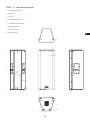
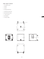
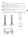
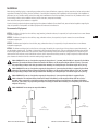
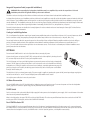
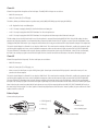
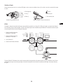
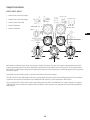
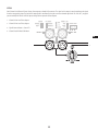
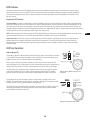
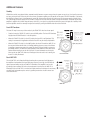
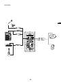
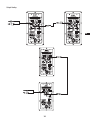
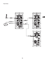
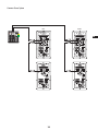
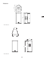
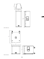
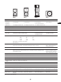
KW Series
User Manual
KW122 – 75° 1000 W active 12" (300 mm) 2-way loudspeaker system
KW152 – 60° 1000 W active 15" (380 mm) 2-way loudspeaker system
KW153 – 75° 1000 W active 15" (380 mm) 3-way loudspeaker system
KW181 – 18" (460 mm) 1000 W subwoofer system
TD-000315-00-C
*TD-000315-00*
IMPORTANT SAFETY PRECAUTIONS AND EXPLANATION OF SYMBOLS
WARNING!
CAUTION: TO REDUCE THE RISK OF ELECTRIC SHOCK, DO NOT REMOVE THE AMPLIFIER COVER.
NO USER-SERVICEABLE PARTS INSIDE. REFER SERVICING TO QUALIFIED PERSONNEL.
The lightning flash with the arrowhead symbol within an equilateral triangle is intended to alert the user to the presence of
uninsulated “dangerous” voltage within the product’s enclosure that may be of sufficient magnitude to constitute a risk of
shock to humans.
The exclamation point within an equilateral triangle is intended to alert the user to the presence of important operation and
maintenance (servicing) instructions in this manual.
Install in accordance with QSC Audio Product’s instructions and under the supervision of a licensed professional installation engineer.
WARNING is used alert the user of situations that may cause physical harm to people.
CAUTION is used to alert the user of situations that may cause physical damage to equipment.
1. Read these instructions.
2. Keep these instructions.
3. Heed all warnings and cautions.
4. Follow all instructions.
5. WARNING! To prevent fire or electric shock, do not expose this equipment to rain or moisture. Do not use this loudspeaker near water.
6. Clean only with a dry cloth.
7. CAUTION: Allow a minimum of 6" (152 mm) clearance at cabinet back for convection cooling. Keep anything that might restrict airflow
away from the rear of the enclosure (for example draperies, fabric, etc.). Do not block any ventilation openings. This product contains an
internal power amplifier that produces heat and requires ventilation.
8. CAUTION: Do not install near any heat sources such as radiators, heat registers, stoves, or other loudspeaker (including amplifiers) that
produce heat.
9. WARNING! This loudspeaker must be properly grounded for your safety. The grounding plug has two blades and a grounding prong.
The third prong is provided for your safety. If the provided plug does not fit your outlet, consult an electrician for the replacement of the
obsolete outlet. Do not cut off the grounding prong or use an adapter that breaks the grounding circuit.
10.CAUTION: Protect the power cord from being walked on or pinched, particularly plugs, convenience receptacles, and the point where they
exit from the loudspeaker.
11. WARNING! This product is NOT equipped with an all-pole mains switch. To fully disconnect the loudspeaker from the AC mains, the AC
power cord must be removed from the AC power source or the loudspeaker AC INLET (IEC block) on the amplifier module. Ensure either
or both ends of the AC power cord are accessible in case of emergency disconnect requirement.
12.CAUTION: Use only attachments/accessories specified by QSC Audio Products, LLC.
13.CAUTION: Use only with hardware, brackets, stands, and components sold with the loudspeaker or by QSC Audio Products, LLC.
14.CAUTION: Unplug the loudspeaker during lightning storms or when unused for long periods of time.
15.CAUTION: Refer all servicing to qualified service personnel. Servicing is required when the loudspeaker has been damaged in any way,
such as power supply cord or plug is damaged, liquid has been spilled or objects have fallen into the loudspeaker, the loudspeaker has
been exposed to rain or moisture, does not operate normally, or has been dropped.
2
EN
16.WARNING! Before placing, installing, rigging, or suspending any speaker product, inspect all hardware, suspension, cabinets, transducers,
brackets and associated equipment for damage. Any missing, corroded, deformed, or non-load rated component could significantly
reduce the strength of the installation or placement. Any such condition severely reduces the safety of the installation and should be
immediately corrected. Use only hardware which is rated for the loading conditions of the installation and any possible short-term,
unexpected overloading. Never exceed the rating of the hardware or equipment.
17. WARNING! Consult a licensed, professional engineer regarding physical equipment installation. Ensure that all local, state and national
regulations regarding the safety and operation of equipment are understood and adhered to.
18.WARNING! KW122 – Do not use a loudspeaker support pole longer than 46" (1168 mm) when supported by QSC’s KW181 subwoofer. The
maximum distance between the bottom of the KW122, and the top of the KW181 shall not exceed 43" (1092 mm).
19.WARNING! KW152 – Do not use a loudspeaker support pole longer than 36" (914 mm) when supported by QSC’s KW181 subwoofer. The
maximum distance between the bottom of the KW152, and the top of the KW181 shall not exceed 33" (838 mm).
20.WARNING! KW153 – Do not use a loudspeaker support pole longer than 36" (914 mm) when supported by QSC’s KW181 subwoofer. The
maximum distance between the bottom of the KW153, and the top of the KW181 shall be 33" (838 mm).
21. CAUTION: The loudspeaker shall not be exposed to liquids. Do not place any objects filled with liquids, such as vases, drinks, etc. on
the loudspeaker.
Warranty (USA only; other countries, see your dealer or distributor)
QSC Audio Products 3 Year Limited Warranty
QSC Audio Products, LLC (“QSC”) guarantees its products to be free from defective material and/or workmanship for a period of three (3) years from
the date of sale and will replace defective parts and repair malfunctioning products under this warranty when the defect occurs under normal installation and use – provided the unit is returned to our factory or one of our authorized service stations via prepaid transportation with a copy of proof of
purchase (i.e., sales receipt). This warranty provides that the examination of the returned product must indicate, in our judgement, a manufacturing
defect. This warranty does not extend to any product which has been subjected to misuse, neglect, accident, improper installation, or where the date
code has been removed or defaced. QSC shall not be liable for incidental and/or consequential damages. This warranty gives you specific legal rights.
This limited warranty is freely transferable during the term of the warranty period.
Customer may have additional rights, which vary from state to state.
In the event that this product was manufactured for export and sale outside of the United States or its territories, then this limited warranty shall not
apply. Removal of the serial number on this product, or purchase of this product from an unauthorized dealer will void this limited warranty.
Periodically, this warranty is updated. To obtain the most recent version of QSC’s warranty statement, please visit www.qscaudio.com.
Contact us at 800-854-4079 or visit our website at www.qscaudio.com.
FCC Statement
NOTE: This equipment has been tested and found to comply with the limits for a Class B digital device, pursuant to Part 15 of the FCC Rules.
These limits are designed to provide reasonable protection against harmful interference in a residential installation. This equipment generates, uses
and can radiate radio frequency energy and, if not installed and used in accordance with the instructions, may cause harmful interference to radio
communications. However, there is no guarantee that interference will not occur in a particular installation. If this equipment does cause harmful
interference to radio or television reception, which can be determined by turning the equipment off and on, the user is encouraged to try to correct
the interference by one or more of the following measures:
• Reorient or relocate the receiving antenna.
• Increase the separation between the equipment and receiver.
• Connect the equipment into an outlet on a circuit different from that to which the receiver is connected.
• Consult the dealer or an experienced radio/TV technician for help.
© Copyright 2010, QSC Audio Products, LLC
QSC® is a registered trademark of QSC Audio Products, LLC
“QSC” and the QSC logo are registered with the U.S. Patent and Trademark Office
All trademarks are the property of their respective owners.
3
EN
Package Contents
KW122, KW152, KW153
KW181
(1) Loudspeaker system
(1) Subwoofer system
(1) Locking NEMA 5-15 power cable
(1) Locking NEMA 5-15 power cable
(1) Locking CEE 7/4 power cable
(1) Locking CEE 7/4 power cable
(1) User Manual CD
(1) User Manual CD
(1) Wiring hookup diagram
(1) Wiring hookup diagram
(1) M20 threaded loudspeaker pole
EN
Features
KW122 – 12", 2-Way Loudspeaker System
1. Birch plywood enclosure
2. Steel grille
3. Front LED
1
4. Cast aluminum handles (3)
5. 1000 W Class D power module
4
6. M10 rigging points (8)
6
6
7. Tilt-Direct™ dual angle pole socket
8. Slip-resistant feet
4
8
8
6
6
2
1
4
6
4
4
4
6
5
8
6
8
3
6
6
8
8
7
8
4
KW152 – 15", 2-Way Loudspeaker System
1. Birch plywood enclosure
2. Steel grille
3. Front LED
4. Cast aluminum handles (2)
5. 1000 W Class D power module
6. M10 rigging points (11)
7. Tilt-Direct™ dual angle pole socket
8. Slip-resistant feet
EN
1
6
6
6
6
6
6
1
2
4
4
4
6
5
6
6
3
6
8
8
6
6
7
8
8
5
6
KW153 – 15", 3-Way Loudspeaker System
1. Birch plywood enclosure
2. Steel grille
3. Front LED
4. Cast aluminum handles (2)
5. 1000 W Class D power module
6. M10 rigging points (11)
7. 35 mm pole socket
1
8. Slip-resistant feet
EN
6
6
6
6
6
6
1
4
2
4
4
6
5
6
6
6
3
8
8
6
6
7
8
8
6
KW181– Single 18" Subwoofer
1. Birch plywood enclosure
2. Steel grille
3. Front LED
4. Cast aluminum handles (2)
5. 1000 W Class D power module
6. M20 threaded pole receptacle
7. 3" heavy duty casters
8. Slip-resistant feet
EN
9. Feet cups for stacking
7
9
9
1
6
9
9
7
1
2
4
3
7
5
8
8
8
8
7
Applications
The KW Series has been primarily designed for portable audio reinforcement. This includes a variety of uses in reinforcement for entertainers and
presenters. The KW122, KW152 and KW153 are all designed to perform well on their own in full-range audio. They can be used singly, in stereo pairs
or in distributed or delayed systems. The KW122 may also be used as a stage monitor.
WARNING! The KW Series loudspeakers weigh 49 lbs and up. Use proper lifting techniques and safety precautions when mounting
on loudspeaker poles. Refer to the Specifications section for the individual weights.
The KW122, KW152, and KW153 are equipped with a 35 mm pole socket that allows use on a speaker stand or on a pole over a KW181 subwoofer.
The pole socket on the KW122 and KW152 features the QSC Tilt-Direct™ system for tilting the enclosures down 7.5° while on a pole. The pole socket
on the KW153 does not allow tilting.
WARNING! When suspending the loudspeakers, installation must be accomplished by or under the supervision of a licensed installation professional. All applicable building codes must be followed.
EN
The KW122, KW152 and KW153 have M10 threaded inserts for suspension with eyebolts.
For extra low-frequency extension and enhancement, the KW181 is perfectly matched to the rest of the KW Series. The KW122, KW152 and KW153
all have a 100 Hz high-pass filter for use with the subwoofer. The KW181 includes a fixed low-pass filter so it will accept full-range input. The KW181
has four large casters for maximum portability. The pole socket on the top of the enclosure is fitted with an M20 threaded insert. The included speaker
pole screws into the socket for a secure fit.
46"
(1168 mm)
KW122 On Stands
KW152 Mounted on KW181
KW122 in Monitor Position
8
Installation
Before placing, installing, rigging, or suspending any speaker product, inspect all hardware, suspension, cabinets, transducers, brackets and associated
equipment for damage. Any missing, corroded, deformed, or non-load rated component could significantly reduce the strength of the installation or
placement. Any such condition severely reduces the safety of the installation and should be immediately corrected. Use only hardware which is rated
for the loading conditions of the installation and any possible short-term, unexpected overloading.
Never exceed the rating of the hardware or equipment.
Consult a licensed, professional engineer regarding physical equipment installation. Ensure that all local, state and national regulations regarding the
safety and operation of loudspeakers and related equipment are understood and adhered to.
Recommended Deployment
KW122: The KW122 is designed to sit on the floor, stage (monitor), subwoofer enclosure, be suspended, or be pole mounted on a 35 mm diameter
loudspeaker support pole.
EN
KW152: The KW152 is designed to sit on the floor, stage, subwoofer enclosure, be suspended, or be pole mounted on a 35 mm diameter
loudspeaker support pole.
KW153: The KW153 was designed to sit on the floor, stage, subwoofer enclosure, be suspended, or be pole mounted on a 35 mm diameter
loudspeaker support pole.
KW181: The KW181 was designed to sit on the floor or on the stage. A threaded pole cup on the top of the enclosure accepts a M20 threaded
mm loudspeaker mounting pole. The KW181 is shipped with a fixed length, M20 threaded pole. There are additional M20 speaker poles available
from third party suppliers. Rubber feet on the enclosure’s bottom help to minimize enclosure movement during operation. Do not pole mount or
stack more than one enclosure on top of the KW181 enclosure. As the casters will wear during normal use, it may be required to insert small foam
pieces between the wheels and frames to minimize rattling at high output levels.
KW122 WARNING! Do not use a loudspeaker support pole longer than 46" (1168 mm) when the KW122 is supported by the KW181
subwoofer. The maximum distance between the bottom of the KW122, and the top of the KW181 shall not exceed 43" (1092 mm).
Use proper lifting techniques and safety precautions when mounting on a loudspeaker pole. The KW122 weighs 49 lbs (22.2 kg).
KW152 WARNING! Do not use a loudspeaker support pole longer than 36" (914 mm) when the KW152 is supported by the KW181
subwoofer. The maximum distance between the bottom of the KW152, and the top of the KW181 shall not exceed 33" (838 mm).
Use proper lifting techniques and safety precautions when mounting on a loudspeaker pole. The KW152 weighs 64 lbs (29.0 kg).
KW153 WARNING! Do not use a loudspeaker support pole longer than 36" (914 mm) when the KW153 is supported by the
KW181 subwoofer. The maximum distance between the bottom of the KW153, and the top of the KW181 shall not exceed 33"
(883 mm). When supported by a stand-alone speaker stand, the maximum distance from the floor to the bottom of the KW153
shall be 53" (1346.2 mm). Use proper lifting techniques and safety precautions when mounting on a loudspeaker pole. The KW153
weighs 88 lbs (39.9 kg).
KW181 WARNING! Do not attempt to suspend the KW181.
43"
(1092 mm)
Between Units
46"
(1168 mm)
Maximum Pole Length
KW122 Pole Mount Maximum
33"
(838 mm)
Between Units
KW152 Pole Mount Maximum
9
36"
(914 mm)
Maximum Pole Length
35
Integrated Suspension Points (suspended installations)
WARNING! When suspending the loudspeakers, installation must be accomplished by or under the supervision of a licensed
installation professional. All applicable building codes must be followed.
The KW122 enclosure has eight, and the KW152 and KW153 enclosures each feature eleven load-rated M10 installation points.
As shipped from the factory, each installation point has a flat head screw installed to acoustically seal the loudspeaker system and retain the sleek look
of the enclosure. These installation points are designed for use with the QSC forged shoulder eyebolts included in the available accessory kit, model
number KW M10 KIT. The installation points may also be used with any forged shoulder eyebolt with an M10 thread provided the length of the thread
is no less than 1.4" (35 mm). When suspending the KW122 horizontally, the KW SUS KIT 122, with pullback bar, is required.
Ensure all pick-point fasteners are installed and correctly tightened in order to maintain enclosure’s rated strength. Contact QSC Technical Services
department for complete information.
Cooling in Installed Applications
EN
This is a self-powered loudspeaker containing an internal power amplifier that produces heat. Allow a minimum of 6" (152 mm) clearance at cabinet
back for convection cooling. Keep anything that might restrict airflow away from the rear of the enclosure (i.e. draperies, fabric, etc.).
Do not install enclosures with their rear panels exposed to direct sunlight. Direct sunlight will heat the amplifier module and reduce its ability to
produce full output. Install sunshades if the application merits. Maximum ambient temperature for full performance to specification is 50° C
(122° F). Do not install enclosures where exposed to rain or other water sources. The enclosure is not weatherproof. Outdoor installations must
provide protection from the elements.
AC Mains
Ensure that the POWER switch is not in the ON position before connecting AC power.
Connect the AC power cord to the AC INLET (IEC) socket on the back of the amplifier by inserting the cord’s
IEC connector fully into the AC INLET on the power amplifier module.
The V-LOCK power cord has a special latching feature to prevent the power cord from being unintentionally
removed. The IEC plug and socket are both blue in color so the power cord can be identified as a KW Series
loudspeaker cord. If the QSC supplied cord becomes lost or damaged, a standard replacement 18 gauge IEC
power cord may be used. However, the latching system functions only with a V-LOCK power cord available
from QSC Audio Products, LLC.
The KW Series is fed by a universal power supply. This power supply is capable of operating the system with AC power input voltages ranging from
100 VAC to 240 VAC at 50 – 60 Hz. There are multiple power cables available for this reason.
Use only the power cable that is correct for your location.
AC Mains Disconnection
Turn the POWER switch to the OFF (not ON) position. Unplug the power cord from the source. To remove the power cord from the loudspeaker
system, grasp the IEC connector’s plastic body, press the yellow latch release button and pull.
POWER Switch
Push in on the top of the rocker switch (labeled ON) to apply AC mains power to the loudspeaker’s power supply. Push in on the bottom of the rocker
switch to turn the powered loudspeaker off.
When in the ON position, the green STBY LED and the red LIMIT (limiter) LED on the rear panel illuminate. After a few seconds the red LIMIT LED
and the green STBY LED extinguish, and the blue POWER LED illuminates.
Rear POWER Indicator LED
The blue POWER LED on the rear panel illuminates when: the AC mains are functioning properly, the AC mains power cord is connected properly,
the POWER switch is in the ON position, and the unit is not in standby. The rear POWER LED extinguishes when the AC mains power cord has been
removed from the loudspeaker or source, the POWER switch is in the off (not ON) position, or the amplifier enters standby.
10
If the rear POWER LED does not illuminate when the POWER switch is placed in the ON position during the first 5 minutes of power being applied,
verify the AC mains power cord is properly attached to the loudspeaker and plugged into the AC source outlet. Verify the outlet is functioning properly.
If the AC mains cord is serviceable and the AC mains outlet is operating properly, but the loudspeaker fails to operate, the loudspeaker may require
servicing. Contact QSC’s Technical Services department.
System Power Sequencing
Proper power-on/power-off sequencing can help prevent unexpected sounds from being produced by the system (pops, clicks, thumps). These
unintended sounds can be unpleasant and take away from the overall professionalism of the presentation.
Always follow the rule “speakers are last on, first off”.
Power-on Sequence: Bring the output level control of the mixer (or other audio source) feeding your speakers to its minimum position. Turn on all
source devices (CD players, mixers, instruments), turn on subwoofer(s) then turn on the “top-boxes” (KW122, KW152, KW153). The level controls on
your mixer may now be brought up.
Power-off Sequence: Turn off “top boxes”, turn off subwoofer(s), and then turn off all source devices.
If a KW Series speaker is being driven from the output of another KW Series unit, it should be turned on after the unit feeding the audio signal, and
turned off before the unit feeding the audio signal.
Input Connections
KW122, KW152, KW153
The KW122, KW152 and KW153 are designed to accept microphone-level and line-level inputs with several different connectors. There are three input
connection points on the input panel.
1. Channel A Mic/Line Input
Combination XLR-M and ¼" Phone Jack
2. Channel B Line Input Combination
XLR-M and ¼" Phone Jack
3. Channel A Mic Level Indicator –
Yellow LED
4. Channel B Line Input Phono (RCA) Jacks
5. Channel A Mic/Line Gain
1
3
2
5
4
6
7
8
9
6. Channel A Signal Present Indicator –
Green LED
7. Channel B Signal Present Indicator –
Green LED
8. Channel A Gain
9. Channel B Gain
11
EN
Channel A
Channel A accepts either microphone or line level inputs. The MIC/LINE IN A inputs can use either a:
• Male XLR connector, or a
• Male 1/4" phone jack (TS or TRS type).
The KW122, KW152, and KW153 feature a 4-position rotary switch (MIC/LINE GAIN) to provide input gain flexibility.
• 0 dB – Regular line level, no additional gain.
• 12 dB – Pre-amp is engaged, primarily for low line levels that need extra gain.
• 24 dB – Pre-amp is engaged and MIC LED illuminates. For direct microphone use.
• 36 dB – Pre-amp is engaged and MIC LED illuminates. For microphones with lower output levels that need extra gain.
EN
The Mic settings (24 and 36 dB) should only be used if a microphone is connected directly to the MIC/LINE IN A. Using the Mic settings for other
purposes may introduce distortion. It is recommended that you move the GAIN A knob to the OFF position, or power down the loudspeaker, before
changing the MIC/LINE GAIN switch. If you change the switch while audio is being processed there will be very noticeable changes in the output level.
The gain for signal delivered on Channel A is set using the GAIN A knob. This control sets the sensitivity of Channel A, as well as the amount of signal
sent to the power amplifier and, in turn, to the loudspeaker components. It also sets the amount of signal sent to the LINE OUT (POST-GAIN MIX).
The green SIGNAL LED illuminates when a signal is present, regardless of the amount of gain set by the GAIN knob. If the LED does not illuminate,
the input is not receiving any signal or the level of the signal is too low; check all connections and the status of the device delivering the signal.
Channel B
Channel B accepts line level input only. The Line Level inputs can use either a:
• Male XLR connector, a
• Male 1/4" phone jack (TS or TRS type), or a
• Mono or stereo line level input on a pair of RCA (phono) jacks. Stereo input received at the RCA input jacks is summed to mono, and is not
passed to the discrete outputs.
The gain for signal delivered on Channel B is set using the GAIN B knob. This control sets the sensitivity of Channel B, as well as the amount of signal
sent to the power amplifier and, in turn, to the loudspeaker components. It also sets the amount of signal sent to the LINE OUT (POST-GAIN MIX).
The green SIGNAL LED illuminates when a signal is present, regardless of the amount of gain set by the GAIN knob. If the LED does not illuminate,
the input is not receiving any signal or the level of the signal is significantly low; check all connections and the status of the device delivering the signal.
Note: Unless the gain controls associated with all active inputs are set to 0 dB, the output signal from the LINE OUT (POST-GAIN MIX) will not be at
the same level as the input signal. If a “slave” speaker is intended to playback at the same level as the “master” speaker, the gain control on the “slave”
speaker should be set to 0 dB.
Balanced Inputs
Connect to the plug as shown.
1 = Shield (ground)
Ground
2 = Plus (+)
— Inverting Input
3 = Minus (-)
+ Non-inverting Input
Balanced Inputs XLR Connector
Balanced Inputs ¼" Phone Jack Connector
12
Unbalanced Inputs
Connect to the plug as shown. If a 3 conductor (TRS) plug is used to connect an unbalanced source, Pin 3 and pin 1 must be connected with a jumper
as shown.
1 = Shield (ground)
Ground
2 = Plus (+)
— Inverting Input
3 = Minus (-)
+ Non-inverting Input
Unbalanced Inputs ¼" Phone Jack Connector
Unbalanced Inputs XLR Connector
EN
KW181
The KW181 is designed to accept line level inputs connected either by male XLR or ¼" phone (TS or TRS) jack. If signal is connected to both Channel
A and Channel B, they are summed together. The gain of the summed signal is then controlled using the GAIN knob. This affects the amount of signal
sent to the amplifier and then to the loudspeaker components.
1. Channel A LINE IN Combination
XLR-M and ¼" Phone Jack
2. Channel B LINE IN Combination
XLR-M and ¼" Phone Jack
3. Green SIGNAL LED
2
1
4. Channel A and B Mixed GAIN Knob
3
4
The green SIGNAL LED illuminates when a signal is present at either input, regardless of the amount of gain as set by the GAIN knob. If the LED does
not illuminate, the input is not receiving any signal, or the level of the signal is too low. Check all connections and the status of the device delivering
the signal.
13
Output Connections
KW122, KW152, KW153
1. Channel A Line Level Discrete Output
2. Channel B Line Level Discrete Output
3. LINE OUT (POST GAIN – MIX)
4. Channel A GAIN Knob
5. Channel B GAIN Knob
EN
2
1
5
4
3
Both Channel A and Channel B have discrete, direct outputs on female XLR connectors. The signal on this output is exactly equivalent to the signal
from the corresponding input. The level of the output signal is not affected by the gain setting for that channel. If a unit is OFF, any signal present on
MIC/LINE IN A or LINE IN B passes through to the respective discrete outputs. Any audio signal present on the RCA (phono) jacks does not get passed
to the discrete outputs.
Signal delivered on the RCA (phono) jacks is not present on the Channel B direct line level output.
The LINE OUT (POST GAIN – MIX) female XLR connector is a mixed output of Channel A, Channel B and the RCA (phono) jacks. This mix is affected
by gain knobs on both Channel A and Channel B and the MIC/LINE GAIN on Channel A, but the output level is still at line level.
Do not connect the LINE OUT (POST GAIN – MIX) of a KW Series system to any INPUT of the SAME UNIT. This output is designed to send signal to
OTHER KW Series units or to other audio equipment. Failure to follow this caution may result in very unpleasant sounds produced at extremely high
output volumes.
14
KW181
Both Channel A and Channel B have discrete, direct outputs on female XLR connectors. The signal on this output is exactly equivalent to the signal
from the corresponding input. The level of the output signal is not affected by the gain set on the subwoofer gain knob. If a unit is OFF, any signal
present on MIC/LINE IN A or LINE IN B passes through to the respective discrete outputs.
1. Channel A Line Level Direct Output
2. Channel B Line Level Direct Output
3. Signal Present Indicator – Green LED
4. Channel A and B Mixed GAIN Knob
EN
2
1
3
4
15
DSP Features
The KW Series features advanced DSP (digital signal processing) circuitry that performs many functions. Some functions are set at the design/
production level and are not user accessible. These functions include crossovers, time alignment, limiting and protection, thermal management
and a number of proprietary features. QSC has designed exclusive DSP functions that greatly enhance the capabilities and performance of the
KW Series systems.
Proprietary DSP Functions
Excursion Limiting: In addition to signal limiting to protect the amplifier and transducers from overload, the KW Series utilizes a proprietary limiter
that prevents woofer over-excursion. Over-excursion occurs when a voltage presented to the woofer causes the cone to physically travel too far. This
builds up excessive heat, stresses the moving parts of the woofer, produces audible artifacts and distortion and reduces the woofer’s lifespan. The
proprietary algorithm contained in Excursion Limiting prevents over-excursion. Voltages that will harm the woofer through over-excursion are reduced
enough to prevent over-excursion without any audible compression, limiting or loss.
DEEP™: Taking advantage of the Excursion Limiter, the DEEP™ (Digital Extension and Excursion Processing) algorithm functions as a highly musical
and non-distorting low-frequency EQ circuit. More on the DEEP function is available in the EQ section of this manual.
Intrinsic Correction™: Introduced on QSC Concert/Touring products, Intrinsic Correction is a proprietary process and set of signal processing
algorithms that address correctable characteristics of transducers and waveguides. The net result is that any KW Series system will present
extraordinarily even and consistent energy throughout the physical listening area of the loudspeaker, resulting in a very musical, acoustically
transparent system.
DSP User Functions
Low-frequency EQ
On the KW122, KW152 and KW153, there are three low-frequency settings. From the factory, the switch
is set to NORM. This means that the loudspeaker system is producing a normal low-frequency signal
through the woofer. This is the standard setting for most applications.
When using one of the top boxes with a subwoofer, the switch should be moved to the EXT SUB
position to engage the 100 Hz high-pass filter. It is also recommended that the 100 Hz high-pass filter be
engaged when using the KW122 as a floor monitor to prevent excessive bass build up on the stage.
For extra low-frequency extension and low-end presence when using one of the top boxes without
a sub, move the switch to the DEEP™ setting. This will engage the proprietary DEEP™ algorithm,
providing increased low-frequency extension without causing distortion or woofer over-excursion.
KW122, KW152, KW153 Low-frequency
EQ Switch
On the KW181 there are two low-frequency settings. From the factory, the MODE switch is set to
NORMAL. This means that the subwoofer system is producing a minimally EQ’d low-frequency signal
through the woofer. This is the standard setting for most applications.
For extra low-frequency extension and low-end presence, move the switch to the DEEP™ setting. This
will engage the proprietary DEEP algorithm, providing increased low-frequency extension without
causing distortion or woofer over-excursion.
KW181 Low-frequency Mode Switch
16
EN
High-frequency EQ
On the KW122, KW152 and KW153 there are two high-frequency settings. From the factory, the
switch is set to FLAT. This means that the loudspeaker system is producing a flat response through
the vocal band. This is the standard setting for most applications.
In voice-only reproduction, the switch can be set to the VOCAL BOOST setting. This will engage EQ
that gives a stronger presence for vocal intelligibility and presence. It is generally not recommended
to use this setting when playing full-range music through the system.
KW122, KW152, KW153 High-frequency
EQ Switch
Subwoofer Polarity
Polarity (sometimes improperly referred to as phase) refers to the voltage of an input signal and
whether it is a positive or negative voltage at any given time. In most cases a positive voltage
causes a woofer cone to move forward with respect to the cabinet orientation, and a negative
voltage then moves the woofer cone backward. Most importantly, speakers reproducing the same
signal or signals that are adjacent in frequency must have the same polarity to get the maximum
output. This is most important for low frequencies. Polarity can be altered by incorrect wiring or
mixer control settings.
The KW181 provides a polarity switch to correct any wiring or mixer setting errors. The polarity
switch is set in the NORMAL position from the factory.
When using the KW181 with KW Series full range loudspeakers, NORMAL polarity will result in the
best bass response if the full range loudspeakers are sitting on or very close to the subwoofers. If
the subwoofers are some distance away from the full range loudspeakers, polarity change may be
of benefit. Start with all subwoofer POLARITY switches in the NORMAL position. Then, with the
system at or near expected operating levels, change the polarity of each subwoofer individually.
Walk around the venue and assess the overall bass response. Select the polarity that results in the
best overall system bass response.
KW181 Polarity Reversal Switch
When using only one KW181 and connecting a LEFT and RIGHT stereo signal, start with the polarity switch in the NORMAL position. With the system
at a reasonable level, change the POLARITY switch and evaluate which polarity results in the most low-frequency output.
17
EN
Additional Features
Standby
All KW Series models are equipped with an automatic standby feature to conserve energy when the systems are not in use. If no signal is present on
any input, or the gain knob is turned to off for five minutes, the power amplifier goes into standby and the green STBY LED illuminates. In this mode,
the amplifier is powered down. A small amount of current will continue to flow from the AC power source into the power supply of the KW Series.
This current keeps the power supply and DSP “awake” to reduce turn on time when the system is brought out of standby. The power-up time of the
amplifier is negligible and is shorter than the latency of the DSP, so no signal is cut off when the KW Series system is brought out of standby. A KW
Series loudspeaker can also be manually brought out of standby by turning the POWER switch off and then back ON.
Front LED Functions
The front LED may be set to any of three modes by the FRONT LED switch on the rear panel.
EN
• From the factory, the FRONT LED switch is set to the PWR position. The front LED illuminates
brightly when the POWER switch is in the ON position.
• When the FRONT LED switch is in the OFF position, the front LED is not illuminated. This
setting is recommended in applications where the front LED may be visually objectionable.
• When the FRONT LED switch is in the LIMIT position, the front LED tracks the LIMIT LED on
the rear panel. When the KW Series is in limiting (meaning that one or more of the limiters
is engaging to protect some part of the system) the front LED glows brightly in response to
the limiting function. This allows the system operator to have awareness of the status of the
limiters without needing to see the rear of the unit. For more information see the section
below on the rear LIMIT LED. When not in limiting and when the unit is not in standby, the
front LED is dimly illuminated.
Front LED Switch
Rear LIMIT LED
The red LIMIT LED can indicate that limiting has taken place to protect and avoid damage to
the amplifier or loudspeaker. If the signal level at any frequency is too high, the DSP limits the
signal to prevent damage and the red LIMIT LED illuminates. If the amplifier is too hot due
to prolonged use at extreme SPL levels or the environment is too hot, the red LIMIT LED is
illuminated. If the red LIMIT LED is on when both GAIN controls are at minimum for 10 minutes,
your KW Series loudspeaker requires service by qualified personnel or should be moved to a
cooler environment.
LIMIT LED
18
Remote Gain Attenuator
A 3-pin “Euro” connector is provided to attenuate the volume of the KW Series loudspeaker
or put the system into standby from a remote location. The Remote Gain connector can
only attenuate the output signal level below the level set by the Channel A and Channel B
Gain knobs.
By varying the voltage on
(pin 2) between
(pin 1) and
(pin 3, ground), the
volume can be linearly controlled. The voltage on
can be created by using a potentiometer
or provided from an external source. Many KW Series systems can be controlled from a single
potentiometer by connecting the pins of multiple KW Series speakers together.
A relay or manual connection can be made between
(pin 2) and
(pin 3, ground) to
effectively mute the output and put the KW Series system into standby mode after 5 minutes.
CAUTION: Do not put more than +5V or less than ground on
(pin 2), or damage may
occur. Do not connect +5V (pin 1) directly to
(pin 3, ground).
Remote Gain Attenuator
Schematics of Proper Wiring for Remote Gain Attenuator
When using a single potentiometer
for one loudspeaker.
Wiring to the 3 pin “Euro” connector.
When using a single potentiometer
for multiple loudspeaker.
19
EN
Input Hookup
EN
12
24
12
24
20
Output Hookup
12
12
24
24
EN
12
24
21
Output Hookup
EN
12
12
24
24
OR
OR
22
Common Standalone Small System (Mono)
12
24
12
24
EN
23
Common Stereo System
LEFT
LEFT
RIGHT
RIGHT
EN
12
12
24
24
24
Dimensions
15.4"
391 mm
15"
381 mm
EN
26"
662 mm
KW122 Dimensions
15.2"
386 mm
17.5"
445 mm
15.2"
386 mm
32.1"
816 mm
KW152 Dimensions
25
16.8"
427 mm
18.5"
469 mm
EN
43.1"
1096 mm
KW153 Dimensions
29.9"
761 mm
23.4"
595 mm
20.1"
510 mm
KW181 Dimensions
26
KW122
KW152
KW153
KW181
Configuration
12" 2-way multipurpose loudspeaker 15" 2-way trapezoidal loudspeaker
15" 3-way trapezoidal loudspeaker
18" subwoofer
Transducers
Low-frequency
Mid-frequency
High-frequency
12" cone transducer
—
1.75" diaphragm compression driver
15" cone transducer
—
1.75" diaphragm compression driver
15" cone transducer
6.5" mid range cone transducer
1.75" diaphragm compression driver
18" cone transducer
—
—
Frequency Response (-6 dB) 53 Hz – 18 kHz
47 Hz – 18 kHz
35 Hz – 18 kHz
40 Hz – 112 kHz
Frequency Range (-10 dB)
50 Hz – 20 kHz
44 Hz – 20 kHz
33 Hz – 20 kHz
37 Hz – 129 Hz
Nominal Coverage (-6 dB)
75° axisymmetric
60° axisymmetric
75° axisymmetric
—
Maximum SPL (1 meter)
131 dB peak
133 dB peak
134 dB peak
135 dB peak
Amplifiers
Power Output
1000 W Class D (500 W LF, 500 W HF) continuous
1000 W Class D (500 W LF,
500 W MF/HF) continuous
1000 W Class D continuous
Input Impedance (Ω)
Channel A XLR / ¼":
0
0
0
0
Mic gain setting
0 dB
+12 dB
+24 dB
+36 dB
Balanced
38k
10k
2.66k
660 Ω
Unbalanced
19k
5k
1.33k
330 Ω
XLR / ¼": 38k balanced / 19k unbalanced
Channel B XLR / ¼": 38k balanced / 19k unbalanced
Channel B RCA: 10k
Controls
Power • Gain A • Gain B • Channel A Input Gain (0 dB / 12 dB / 24 dB / 36 dB) •
LF Mode (Ext Sub / Norm/DEEP™) • HF Mode (Flat / Vocal Boost) Front LED (On / Off / Limit) Power • Gain • LF Mode (Normal /
DEEP™) • Polarity (Normal / Reverse) •
Front LED (On / Off / Limit)
Indicators
Power • Signal A • Signal B • Standby • Limit • Mic (24 dB and 36 dB settings)
Power • Signal • Standby • Limit
Connectors
Balanced female XLR / ¼" line/mic level input • Balanced female XLR / ¼" line level input • Dual Balanced male
XLR full range line level out • Balanced male XLR “mix” out • Stereo RCA line level input • Remote gain control •
Locking IEC power connector
Dual balanced female XLR / ¼" line
level input • Dual Balanced male XLR
full range line level out • Remote gain
control • Locking IEC power connector
Cooling
On demand, 50 mm variable speed fan
Amplifier Protection
Thermal limiting • Output overcurrent • Overtemperature muting • GuardRail™
Transducer Protection
Thermal limiting • Excursion limiting
AC Power Input
Universal power supply 100 – 240 VAC, 50 – 60 Hz
AC Power Consumption 100 VAC, 2.3 A • 120 VAC, 2.01 A • 230 VAC, 1.13 A
1/8 Power
Enclosure
15 mm painted birch plywood
Finish
Black textured paint
Grille
Black powder coated 16 gauge steel
Dimensions (HWD)
26" x 15" x 15.4"
660 mm x 381 mm x 391 mm
32.1" x 17.5" x 15.2"
816 mm x 445 mm x 386 mm
43.1" x 18.5" x 16.8"
1094 mm x 470 mm x 427 mm
20.1" x 23.4" x 29.9" with casters
510 mm x 595 mm x 761 mm with casters
Weight (Net)
49 lb (22.2 kg)
62 lb (28 kg)
87 lb (39.5 kg)
88 lb (40 kg)
Available Accessories
KW SUS KIT 122 • KW122 COVER •
KW M10 KIT
KW152 COVER • KW M10 KIT
KW153 COVER • KW M10 KIT
KW181 COVER
Specifications subject to change without notice.
27
EN
Mailing Address:
QSC Audio Products, LLC
1675 MacArthur Boulevard
Costa Mesa, CA 92626-1468 USA
Telephone Numbers:
Main Number: 714-754-6175
Sales & Marketing: 714-957-7100 or toll free (USA only) 800-854-4079
Customer Service: 714-957-7150 or toll free (USA only) 800-772-2834
Facsimile Numbers:
Sales & Marketing FAX: 714-754-6174
Customer Service FAX: 714-754-6173
World Wide Web:
qscaudio.com
E-mail:
[email protected]
[email protected]
© 2010 QSC Audio Products, LLC. All rights reserved. QSC and the QSC logo are registered trademarks of QSC Audio Products, LLC in the U.S. Patent and Trademark office and other countries. Tilt-Direct,
DMT, Intrinsic Correction, DEEP and GuardRail are all trademarks of QSC Audio Products, LLC. All other trademarks are the property of their respective owners. Patents may apply or be pending.
KW Series User Manual 04/12/10


![[Manual Makeup] - inverter & Plc](http://vs1.manualzilla.com/store/data/005906079_1-ccf407c70ed6dc9ae9bfcbd31676317c-150x150.png)