1
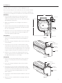
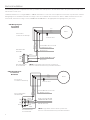
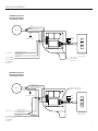
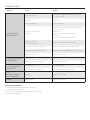
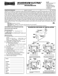
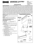
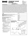
INSTRUCTION BOOK FOR
Designer Contour® Electrol®
Important Safety Instructions
When using your video equipment, basic safety precautions
should always be followed, including the following:
1.
Read and understand all instructions before using.
2. Position the cord so that it will not be tripped over, pulled, or
contact hot surfaces.
3. If an extension cord is necessary, a cord with a current rating
at least equal to that of the appliance should be used. Cords
rated for less amperage than the appliance may overheat.
4. To reduce the risk of electric shock, do not disassemble this
appliance. Contact an authorized service dealer when repair
work is required. Incorrect reassembly can cause electric
shock when the appliance is used subsequently.
5. The use of an accessory attachment not recommended by
the manufacturer may cause a risk of fire, electric shock, or
injury to persons.
Save These Instructions
2
Installation
Carefully unpack screen and remove outer wrapping from case.
Remove the black tape from the slat bar after the case has been installed.
There are three ways to install the Designer Contour Electrol: Wall Mount,
Ceiling Mount, or Ceiling Hook. Procedures for each method are as follows:
4 1/4"
Wall Mount
1. Secure the wall mount bracket to the wall at the desired
height. Bracket should be fastened to wall studs or some
reinforcement within the wall. Concrete or brick walls require
special fasteners and anchors.
Case Hook
5/16"
9/16"
2. Make sure the bracket is level. See figure 1 for reference
dimensions.
3. Keep in mind you will need at least 5/8" between the ceiling
and the top of the wall mount bracket to be able to position
the case on the bracket.
4 5/8"
Wall Mount
Bracket
4. Mount the screen case on the wall bracket as shown in figure 1.
Be sure the case is fully seated on the bracket. Tighten the
stop screws against the wall bracket.
Ceiling Mount
1. Do not remove the wall mount bracket, even if you are not
using it for mounting. This provides structural stability to
the case.
Stop Screw
Figure 1
2. Be sure the ceiling has adequate reinforcement to attach the
screen brackets.
Set Screws (2)
Ceiling
Mount Holes
3. The top of the screen case has a channel that the ceiling
mount brackets slide into. Remove the end cap on the right
end of the case and insert the brackets into the case channel.
Lock the brackets in place by tightening two set screws. Refer
to figure 2. Mount cannot be more than 12" from end of case.
Endcap
Screws (3)
Endcap
4. Hold the screen case up to the ceiling and mark the hole
locations. Drill holes into the ceiling and attach screen with
the appropriate fasteners for your ceiling.
Ceiling Hook
1. Do not remove the wall mount bracket, even if you are not
using it for mounting. This provides structural stability to
the case.
Figure 2
Set Screws (2)
2. Be sure the ceiling has adequate reinforcement to attach
a hook anchor.
Hook Mount
Hole
3. The top of the screen case has a channel that the ceiling
hook brackets slide into. Remove the end cap on the right
end of the case and insert the brackets into the case channel.
Lock the brackets in place by tightening two set screws.
Refer to figure 3.
Endcap
Screws (3)
Endcap
4. The brackets can be attached anywhere within 12" of the end
of the case.
5. Attach an S-hook or similar fastener to the large center hole
on the bracket.
Figure 3
3
Electrical Installation
Internal wiring has been completed at the factory. Installer must route power to the wall switch and to the junction box located on the
left end of the screen case.
Standard installation is for a single 120VAC or 240VAC wall switch to control the screen. Optional Control units may have been ordered.
Wiring diagrams for the built-in VPI and low voltage control are included in these instructions. Refer to additional instructions for the
external VPI, external low voltage control, SCB-100 and SCB-200. Refer to the appropriate wiring diagram for your screen.
120V Wiring Diagram
For Standard
Wall Switch
White
Black
Red
Green
Junction Box
Located In Left Endcap
Motor
White
Black (Down)
Red (Up)
Ground To Case
SPDT Switch with
Center Off
AC (Common)
Black
Up
Off
Red
Down
This Switch Can Not
be used with LVC.
Blue
Brown
Black
Green
Junction Box
Located In Left Endcap
Off
Down
MOTOR
Ground To Case
Blue
Brown (Down)
Black (Up)
Rear or DPDT Switch
with Center Off
AC HOT 120VAC 60HZ 1 AMP
Black/Yellow
NOTE: A single switch cannot be used to operate more
than one screen. Contact the factory for further information.
240V Wiring Diagram
For Standard
Wall Switch
Up
Ground-Must Be Connected
To Building Ground
Brown
BLUE JUMPER
WIRE
Ground-Must Be Connected
To Building Ground
Brown and Yellow AC HOT
220/240 VAC 50HZ 2 AMP.
Blue AC (Common)
Black
This Switch Can Not
be used with LVC.
4
NOTE: A single switch cannot be used to operate more
than one screen. Contact the factory for further information.
Electrical Installation
120V Wiring Diagram
With Optional Built-In
Low Voltage Control
Red
Black
White (Common)
Motor
EYE AUX
Ground To Case
Black
White
Red
Up
Stop
Down
White (Common)
120VAC 60HZ
Black (Hot)
Ground-Must
Be Connected
To Building
Ground
Green
Optional RF
or IR Remote
Connector
Low-Voltage
Wall Switch
240V Wiring Diagram
With Optional Built-In
Low Voltage Control
Black (Up)
Brown (Down)
Blue (Common)
Motor
Optional RF or IR
Remote Connector
240VAC 50HZ
Black
White
Red
Up
Stop
Down
Blue (Common)
Brown (Hot)
Ground-Must
Be Connected
To Building
Ground
AUX EYE
Black
Ground To Case
Green
Black
Low-Voltage
Wall Switch
5
Screen Adjustment
Screen travel is stopped automatically in the down and up
positions by the limit switches that are preset at the factory.
If it’s necessary to adjust for more or less drop follow the steps
below. The case cover must be removed to access the motor
limit switches.
Remove the case cover screw from both ends of the screen.
See figure 4. Be sure to hold the cover while removing the
screws.
Rotate the cover up and away from the case until it can
be removed.
Figure 4
SETTING THE DOWN LIMIT POSITION
To Reduce Screen Drop: Turn the red limit switch screw
clockwise to decrease the amount of screen drop. Run the
screen down to test the stop position. If the screen drops too far,
raise the screen about one foot and adjust the limit switch again.
Repeat until the desired position is set.
To Increase Screen Drop: Turn the red limit switch screw
counterclockwise to increase the amount of screen drop. Run the
screen down to test the stop position. If the screen does not
drop enough, raise the screen about one foot and adjust the limit
switch again. Repeat until the desired position is set.
6
CAUTION: Do not adjust for more drop than what was
ordered. At least 1-1/2 wraps of fabric must remain on the
roller. This screen comes standard with 0" or 2" black at
top. See the specification data sheet for details.
ATTENTION! N'effectuez pas de réglage pour obtenir un
déroulement supérieur à celui commandé. Au moins 1 à 1/2
tour de toile doit être maintenu sur le cylindre. Cet écran est
doté de série d'une bande noire supérieure de 0 cm (0 po) ou
5 cm (2 po). Consultez la fiche technique pour plus de
renseignements.
Hook
Rotate Up
Figure 5
Case Cover
Screw
Troubleshooting
Symptom
Cause
Solution
Incorrect line voltage.
Verify 115-125V (or 220-240V). If insufficient voltage, rewire
incoming electric line.
Blown fuse.
Replace fuse.
Tripped circuit breaker.
Reset circuit breaker.
Check above. Tighten all loose wire connections. Correct any
improper connections.
Screen will not operate.
No power to operating switch
or junction.
Motor does not hum.
Down Position
Check for power across black and white leads.
Up Position
Check for power across red and white leads.
Power at junction box
Thermal overload tripped.
Let motor cool down for 15 minutes. Try again.
Broken wire in the “down” or “up” position.
Check for continuity. Cut off old splice and reconnect.
Defective motor, limit switch or capacitor.
Replace motor assembly. NOTE: Motor is a sealed assembly.
Capacitor burned out.
Replace motor assembly.
Lost roller wrap.
See instructions below.
“Down” limit switch out of adjustment.
See installation instructions.
Lost roller wrap.
See instructions below.
“Up” limit switch out of adjustment.
Adjust “up” limit switch. Call for information.
Noise.
NOTE: Screen will operate
with a low pitched hum.
Gear noise.
Replace motor assembly.
Coasting.
Defective brake.
Replace motor assembly.
Incorrect stopping position in
downward direction.
Incorrect stopping position in
upward direction.
Restoring Lost Roller Wrap
1. Tape a strap to the bottom of the screen surface.
2. Push strap over back of roller.
3. Feed fabric as you pull strap to draw fabric over top of roller.
4. Remove tape and strap.
7
LIMITED ONE YEAR WARRANTY ON DA-LITE PRESENTATION PRODUCTS
Milestone AV Technologies LLC warrants certain Da-Lite branded products to the original purchaser only, to be free from defects in
materials and workmanship for a period of one (1) year from the date of purchase by the original purchaser; provided they are properly
operated according to Da-Lite’s instructions and are not damaged due to improper handling or treatment after shipment from the
factory.
This warranty does not apply to equipment showing evidence of misuse, abuse or accidental damage, or which has been tampered
with or repaired by a person other than authorized Da‑Lite personnel.
Da-Lite’s sole obligation under this warranty shall be to repair or to replace (at Da-Lite’s option) the defective part of the merchandise.
Returns for service should be made to your Da-Lite dealer. If it is necessary for the dealer to return the screen or part to Da-Lite,
transportation expenses to and from Da-Lite are payable by the purchaser and Da-Lite is not responsible for damage in shipment.
To protect yourself against damage or loss in transit, insure the product and prepay all transportation expenses.
TO THE MAXIMUM EXTENT PERMITTED BY APPLICABLE LAW, THIS WARRANTY IS IN LIEU OF ALL OTHER WARRANTIES, EXPRESS
OR IMPLIED, INCLUDING WARRANTIES AS TO FITNESS FOR USE AND MERCHANTABILITY. Any implied warranties of fitness for use,
or merchantability, that may be mandated by statute or rule of law are limited to the one (1) year warranty period. This warranty gives
you specific legal rights, and you may also have other rights, which vary from state-to-state. TO THE MAXIMUM EXTENT PERMITTED
BY APPLICABLE LAW, NO LIABILITY IS ASSUMED FOR EXPENSES OR DAMAGES RESULTING FROM INTERRUPTION IN OPERATION
OF EQUIPMENT, OR FOR INCIDENTAL, DIRECT, OR CONSEQUENTIAL DAMAGES OF ANY NATURE.
In the event that there is a defect in materials or workmanship of a Da-Lite product, you may contact our Sales Partners at PO Box 137,
Warsaw, IN 46581-0137, (574) 267-8101, (800) 622-3737.
IMPORTANT: THIS WARRANTY SHALL NOT BE VALID AND DA-LITE BRANDED PRODUCTS SHALL NOT BE BOUND BY THIS
WARRANTY IF THE PRODUCT IS NOT OPERATED IN ACCORDANCE WITH THE DA-LITE WRITTEN INSTRUCTIONS.
Keep your sales receipt to prove the date of purchase and your original ownership.
A Milestone AV Technologies Brand
3100 North Detroit Street
Warsaw, Indiana 46582
P: 574.267.8101 or 800.622.3737
F: 574.267.7804 or 877.325.4832
E: [email protected]
www.da-lite.com
DL–0177 (Rev. 2) 09.14
© 2014 Milestone AV Technologies LLC. Printed in U.S.A.
89697