1
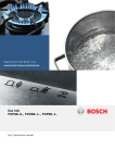
Extractor hood
siemens-home.com/welcome
en ,QVWUXFWLRQVIRULQVWDOODWLRQDQGXVH
Register
your
product
online
en
Table of contents
INSTRUCTION MANUAL.......................................................... 2
sno i t cur t sen I
rof
8 Intended use................................................................... 2
( Important safety information ........................................ 2
7 Environmental protection ............................................. 4
Ç Operating modes ........................................................... 4
1 Operating the appliance................................................ 5
2 Cleaning and maintenance ........................................... 8
3 Trouble shooting............................................................ 9
4 Customer service ........................................................ 10
INSTALLATION INSTRUCTIONS........................................... 11
( Important safety information ...................................... 11
K General information..................................................... 13
5 Installation.................................................................... 14
INSTRUCTION MANUAL
Produktinfo
Additional information on products, accessories,
replacement parts and services can be found at
www.siemens-home.com and in the online shop
www.siemens-eshop.com
8Intended use
Read these instructions carefully. Only then
will you be able to operate your appliance
safely and correctly. Retain the instruction
manual and installation instructions for future
use or for subsequent owners.
The appliance can only be used safely if it is
correctly installed according to the safety
instructions. The installer is responsible for
ensuring that the appliance works perfectly at
its installation location.
e s u dedne t n I
2
no i t a l a t s n i
This appliance is intended for domestic use
and the household environment only. The
appliance is not intended for use outside. Do
not leave the appliance unattended during
operation. The manufacturer is not liable for
damage which is caused by improper use or
incorrect operation.
This appliance is intended for use up to a
maximum height of 2000 metres above sea
level.
This appliance may be used by children over
the age of 8 years old and by persons with
reduced physical, sensory or mental
capabilities or by persons with a lack of
experience or knowledge if they are
supervised or are instructed by a person
responsible for their safety how to use the
appliance safely and have understood the
associated hazards.
Children must not play with, on, or around the
appliance. Children must not clean the
appliance or carry out general maintenance
unless they are at least 8 years old and are
being supervised.
Keep children below the age of 8 years old at
a safe distance from the appliance and power
cable.
Check the appliance for damage after
unpacking it. Do not connect the appliance if it
has been damaged in transport.
This appliance is not intended for operation
with an external clock timer or a remote
control.
dna
(Important safety
information
: Warning
no i t amro f n i y t e f as t na t ropmI
Danger of suffocation!
Packaging material is dangerous to children.
Never allow children to play with packaging
material.
: Warning
Danger of death!
Risk of poisoning from flue gases that are
drawn back in.
esu
Important safety information
Always ensure adequate fresh air in the room
if the appliance is being operated in exhaust
air mode at the same time as room airdependent heat-producing appliance is being
operated.
Room air-dependent heat-producing
appliances (e.g. gas, oil, wood or coaloperated heaters, continuous flow heaters or
water heaters) obtain combustion air from the
room in which they are installed and discharge
the exhaust gases into the open air through an
exhaust gas system (e.g. a chimney).
In combination with an activated vapour
extractor hood, room air is extracted from the
kitchen and neighbouring rooms - a partial
vacuum is produced if not enough fresh air is
supplied. Toxic gases from the chimney or the
extraction shaft are sucked back into the living
space.
Adequate incoming air must therefore
always be ensured.
■
An incoming/exhaust air wall box alone will
not ensure compliance with the limit.
Safe operation is possible only when the
partial vacuum in the place where the heatproducing appliance is installed does not
exceed 4 Pa (0.04 mbar). This can be
achieved when the air needed for combustion
is able to enter through openings that cannot
be sealed, for example in doors, windows,
incoming/exhaust air wall boxes or by other
technical means.
■
en
: Warning
Risk of fire!
■
Grease deposits in the grease filter may
catch fire.
Clean the grease filter at least every
2 months.
Never operate the appliance without the
grease filter.
Risk
of fire!deposits in the grease filter may
■
Grease
catch fire. Never work with naked flames
close to the appliance (e.g. flambéing). Do
not install the appliance near a heatproducing appliance for solid fuel (e.g.
wood or coal) unless a closed, nonremovable cover is available. There must
be no flying sparks.
Risk
of oil
fire!
■
Hot
and fat can ignite very quickly. Never
leave hot fat or oil unattended. Never use
water to put out burning oil or fat. Switch off
the hotplate. Extinguish flames carefully
using a lid, fire blanket or something similar.
Risk
of fire!
■
When
gas burners are in operation without
any cookware placed on them, they can
build up a lot of heat. A ventilation
appliance installed above the cooker may
become damaged or catch fire. Only
operate the gas burners with cookware on
them.
Risk
of fire! several gas burners at the same
■
Operating
time gives rise to a great deal of heat. A
ventilation appliance installed above the
cooker may become damaged or catch fire.
Never operate two gas burners
simultaneously on the highest flame for
longer than 15 minutes. One large burner of
more than 5 kW (wok) is equivalent to the
power of two gas burners.
: Warning
Risk of burns!
The accessible parts become very hot when in
operation. Never touch hot parts. Keep
children at a safe distance.
: Warning
In any case, consult your responsible Master
Chimney Sweep. He is able to assess the
house's entire ventilation setup and will
suggest the suitable ventilation measures to
you.
Unrestricted operation is possible if the vapour
extractor hood is operated exclusively in the
circulating-air mode.
Risk of injury!
■
Components inside the appliance may have
sharp edges. Wear protective gloves.
Risk
of injury!
■
Items
placed on the appliance may fall
down. Do not place any objects on the
appliance.
Risk
of injury!
■
The
light emitted by LED lights is very
dazzling, and can damage the eyes (risk
group 1). Do not look directly into the
switched on LED lights for longer than 100
seconds.
3
en
Environmental protection
: Warning
Risk of electric shock!
■
A defective appliance may cause electric
shock. Never switch on a defective
appliance. Unplug the appliance from the
mains or switch off the circuit breaker in the
fuse box. Contact the after-sales service.
Risk
of electric
shock!are dangerous. Repairs
■
Incorrect
repairs
may only be carried out and damaged
power cables replaced by one of our
trained after-sales technicians. If the
appliance is defective, unplug the appliance
from the mains or switch off the circuit
breaker in the fuse box. Contact the aftersales service.
Risk
electric
■
Doofnot
use shock!
any high-pressure cleaners or
steam cleaners, which can result in an
electric shock.
7Environmental protection
Environmentally-friendly disposal
no i t ce t orp l a t nemnor i vnE
Dispose of packaging in an environmentally-friendly
manner.
This appliance is labelled in accordance with
European Directive 2012/19/EU concerning
used electrical and electronic appliances
(waste electrical and electronic equipment WEEE). The guideline determines the
framework for the return and recycling of used
appliances as applicable throughout the EU.
ÇOperating modes
Exhaust air mode
sedom gn i t arepO
The air which is drawn in is cleaned
by the grease filters and conveyed to
the exterior by a pipe system.
Causes of damage
Caution!
Risk of damage due to corrosion. Always
switch on the appliance while cooking to avoid
condensation. Condensate can produce
corrosion damage.
Always replace faulty bulbs to prevent the
remaining bulbs from overloading.
Risk of damage due to ingress of humidity into
the electronic circuitry. Never clean operator
controls with a wet cloth.
Surface damage due to incorrect cleaning.
Clean stainless steel surfaces in the direction
of the grain only. Do not use any stainless
steel cleaners for operator controls.
Surface damage due to strong or abrasive
cleaning agents. Never use strong and
abrasive cleaning agents.
Risk of damage from returning condensate.
Install the exhaust duct in such a way that it
falls away from the appliance slightly (1°
slope).
4
Note: The exhaust air must not be conveyed into a
functioning smoke or exhaust gas flue or into a shaft
which is used to ventilate installation rooms which
contain heat-producing appliances.
■
■
Before conveying the exhaust air into a nonfunctioning smoke or exhaust gas flue, obtain the
consent of the heating engineer responsible.
If the exhaust air is conveyed through the outer wall,
a telescopic wall box should be used.
Circulating-air mode
The air which is drawn in is cleaned by
the grease filters and an activated
carbon filter and conveyed back into the
kitchen.
Notes
■
To bind odours in circulating-air mode, you must
install an activated carbon filter. The different options
for operating the appliance in circulating-air mode
can be found in the brochure. Alternatively, ask your
dealer. The required accessories are available from
specialist retailers, from customer service or from
the Online Shop.
■
For appliances with an additional internal filter, only
the CleanAir recirculation module (see Accessories
for circulating-air mode) can be used.
Operating the appliance
1Operating the appliance
These instructions apply to several appliance variants. It
is possible that individual features are described which
do not apply to your appliance.
ecna i l p a eh t gn i t arepO
en
Lighting
The lighting can be switched on and off independently
of the fan.
Press the A button.
Setting the brightness
Note: Switch on the extractor hood when you start
cooking and switch it off again several minutes after you
have finished cooking. This is the most effective way of
removing the kitchen fumes.
Press and hold the A button until the desired
brightness is reached.
Control panel model 1
When the metal mesh grease filters or the activated
carbon filter are saturated, a signal sounds for approx.
4 seconds after the fan is switched off.
In addition, the corresponding symbol appears in the
display:
Control panel
Saturation display
■
Explanation
# Fan on/off
-
Reduce the fan settings/fan run-on time
+
Increase the fan settings/intensive setting 1, 2
Light on/off/dimming
A
Setting the fan
Switching on the appliance
■
■
Press the # button.
The fan starts at setting ƒ.
Press the + or - button to change the fan strength.
Switching off
Press the # button.
■
If you have not yet done so, the metal mesh grease
filters should be cleaned or the activated carbon filter
changed now.
For instructions on how to clean the metal mesh grease
filters, please refer to the section Cleaning and
maintenance.
While the saturation displays are flashing, they can be
reset. To do this, press the – button.
Switching over the display for circulating-air mode
For circulating-air mode, the electronic control display
must be switched over accordingly:
■
■
Intensive setting
You can use the intensive setting if there is a large
build-up of odours and fumes/vapours.
Press the + button when the fan is at setting „.
The intensive setting2‚ is activated. Pressing the +
button again activates the intensive setting 2 ƒ.
After approx. six minutes, the electronics automatically
reduce the fan to a lower setting . If you want to end the
intensive setting before the preset time expires, press
the - button until the required fan setting is reached.
Fan run-on time
Metal mesh grease filter:!
Activated carbon filter: "
■
The extractor hood must be connected and switched
off.
Press the # and - buttons at the same time until the
™" display for starter sets for circulating-air mode
or
the ’" display for CleanAir circulating air modules
lights up.
Repeatedly press the button combination to switch
the electronic control display back to exhaust air
mode (! display).
Audible signal
Switching on the acoustic signal
When the fan is switched off, press the # and + at the
same time for approx. three seconds. An
acknowledgement signal sounds.
Switching off the acoustic signal
Repeat the "Switching on the acoustic signal" process.
Press the - button until x‚ appears.
After approx. ten minutes, the fan switches off
automatically.
5
en
Operating the appliance
Control panel model 2
Saturation display
Control panel
When the metal mesh grease filters or the activated
carbon filter are saturated, a signal sounds for approx.
4 seconds after the fan is switched off.
In addition, the corresponding symbol appears in the
display:
Explanation
# Fan on/off
A
Light on/off/dimming
+
Reduce the fan settings
Increase the fan settings/intensive setting 1, 2
Boost function (short-term maximum power)
&
x Fan run-on time
Setting the fan
Switching on the appliance
■
■
Press the # button.
The fan starts at setting ƒ.
Press the + or - button to change the fan strength.
Switching off
Metal mesh grease filter:!
Activated carbon filter: "
■
■
If you have not yet done so, the metal mesh grease
filters should be cleaned or the activated carbon filter
changed now.
For instructions on how to clean the metal mesh grease
filters, please refer to the section Cleaning and
maintenance.
While the saturation displays are flashing, they can be
reset. To do this, press the – button.
Switching over the display for circulating-air mode
For circulating-air mode, the electronic control display
must be switched over accordingly:
The extractor hood must be connected and switched
off.
Press the # and x buttons at the same time until
the
™" display for starter sets for circulating-air mode
or
the ’" display for CleanAir circulating air modules
lights up.
Repeatedly press the button combination to switch
the electronic control display back to exhaust air
mode (! display).
■
■
Press the # button.
Intensive setting
You can use the intensive setting if there is a large
build-up of odours and fumes/vapours.
Press the + button when the fan is at setting „.
■
The intensive setting2‚ is activated. Pressing the +
button again activates the intensive setting 2 ƒ.
After approx. six minutes, the electronics automatically
reduce the fan to a lower setting . If you want to end the
intensive setting before the preset time expires, press
the - button until the required fan setting is reached.
Boost function
The boost function is a short-term maximum power
setting which can be activated in any fan setting.
Press the & button. After approx. 20 seconds, the fan
switches back to the previously set fan setting.
Fan run-on time
Press the x button.
Audible signal
Switching on the acoustic signal
When the fan is switched off, press the # and + at the
same time for approx. three seconds. An
acknowledgement signal sounds.
Switching off the acoustic signal
Repeat the "Switching on the acoustic signal" process.
Control panel model 3
Control panel
The fan continues to operate for a further 10 minutes,
and switches off automatically after this time. If the
lighting is switched on, it remains on.
Press the x button to end the fan run-on time early.
Lighting
The lighting can be switched on and off independently
of the fan.
Press the A button.
Setting the brightness
Press and hold the A button until the desired
brightness is reached.
6
Explanation
# Fan on/off
A
Light on/off/dimming
+
Reduce the fan settings
Increase the fan settings/intensive setting 1, 2
Boost function (short-term maximum power)
&
! Automatic mode with fan run-on time
Operating the appliance
Setting the fan
Switching on the appliance
■
■
Press the # button.
The fan starts at setting ƒ.
Press the + or - button to change the fan strength.
Lighting
The lighting can be switched on and off independently
of the fan.
Press the A button.
Setting the brightness
Switching off
Press and hold the A button until the desired
brightness is reached.
Press the # button.
Saturation display
Intensive setting
You can use the intensive setting if there is a large
build-up of odours and fumes/vapours.
Press the + button when the fan is at setting „.
The intensive setting2‚ is activated. Pressing the +
button again activates the intensive setting 2 ƒ.
After approx. six minutes, the electronics automatically
reduce the fan to a lower setting . If you want to end the
intensive setting before the preset time expires, press
the - button until the required fan setting is reached.
Boost function
The boost function is a short-term maximum power
setting which can be activated in any fan setting.
Press the & button. After approx. 20 seconds, the fan
switches back to the previously set fan setting.
Automatic mode
Switching on the appliance
Press the # button.
The fan starts at ƒ setting.
■
Press the ! button.
The optimum fan setting ‚, ƒ or „ is automatically
set via a sensor.
Switching off the appliance
■
Press the ! or # button to switch off automatic
mode.
The fan switches off automatically if the sensor no
longer detects a change in the air quality of the room.
The automatic mode lasts 4 hours at most.
Sensor control
en
When the metal mesh grease filters or the activated
carbon filter are saturated, a signal sounds for approx.
4 seconds after the fan is switched off.
In addition, the corresponding symbol appears in the
display:
■
■
Metal mesh grease filter:!
Activated carbon filter: "
If you have not yet done so, the metal mesh grease
filters should be cleaned or the activated carbon filter
changed now.
For instructions on how to clean the metal mesh grease
filters, please refer to the section Cleaning and
maintenance.
While the saturation displays are flashing, they can be
reset. To do this, press the – button.
Switching over the display for circulating-air mode
For circulating-air mode, the electronic control display
must be switched over accordingly:
■
■
■
The extractor hood must be connected and switched
off.
Press the # and ! buttons at the same time until
the
™"display for starter sets for circulating-air mode or
’" display for CleanAir circulating air modules
lights up.
Repeatedly press the button combination to switch
the electronic control display back to exhaust air
mode (! display).
Audible signal
Switching on the acoustic signal
In automatic mode, a sensor in the extractor hood
detects the intensity of the cooking and roasting fumes.
Depending on the setting of the sensor, the fan
automatically switches to another fan setting.
When the fan is switched off, press the # and + at the
same time for approx. three seconds. An
acknowledgement signal sounds.
Switching off the acoustic signal
Default sensitivity setting: †
Repeat the "Switching on the acoustic signal" process.
Lowest sensitivity setting: ‹
Highest sensitivity setting: Š
If the sensor control responds too quickly or too slowly,
it can be changed accordingly:
1. When the fan is switched off, press the
! button
and hold it for approx. 4 seconds. The setting is
displayed.
2. The setting of the sensor control is changed by
pressing the + or – button.
3. To confirm the entries, press and hold the !
button for approx. 4 seconds.
7
en
Cleaning and maintenance
2Cleaning and maintenance
: Warning
ecnane t n i am dna gn i nae lC
Risk of burns!
The appliance will become hot during operation,
especially near the bulbs. Allow the appliance to cool
down before cleaning.
Area
Glass
: Warning
Operating controls
Risk of electric shock!
Penetrating moisture may result in an electric shock.
Clean the appliance using a damp cloth only. Before
cleaning, pull out the mains plug or switch off the circuit
breaker in the fuse box.
: Warning
Risk of electric shock!
Do not use any high-pressure cleaners or steam
cleaners, which can result in an electric shock.
: Warning
Risk of injury!
Components inside the appliance may have sharp
edges. Wear protective gloves.
Cleaning agents
Observe the information in the table to ensure that the
different surfaces are not damaged by using the wrong
type of cleaning agent. Do not use
■
■
■
■
harsh or abrasive cleaning agents,
cleaning agents with a high concentration of alcohol,
hard scouring pads or sponges,
high-pressure cleaners or steam cleaners.
Wash new sponge cloths thoroughly before use.
Follow all instructions and warnings included with the
cleaning agents.
Area
Stainless steel
Cleaning agents
Hot soapy water:
Clean with a dish cloth and dry with a soft
cloth.
Clean stainless steel surfaces in the direction
of the grain only.
Special stainless steel cleaning products are
available from our after-sales service or from
specialist retailers. Apply a very thin layer of
the cleaning product with a soft cloth.
Painted surfaces
Hot soapy water:
Clean using a damp dish cloth and dry with a
soft cloth/towel.
Do not use any stainless steel cleaners.
Aluminium and plastic Glass cleaner:
Clean with a soft cloth.
Cleaning the metal mesh grease filters
These instructions apply to several appliance variants. It
is possible that individual features are described which
do not apply to your appliance.
: Warning
Risk of fire!
Grease deposits in the grease filter may catch fire.
Clean the grease filter at least every 2 months.
Never operate the appliance without the grease filter.
Notes
■
Do not use any aggressive, acidic or alkaline
cleaning agents.
■
When cleaning the metal mesh grease filters, also
clean the holder for the metal mesh grease filters in
the appliance using a damp cloth.
■
The metal mesh grease filters can be cleaned in the
dishwasher or by hand.
By hand:
Note: You can use a special grease solvent for
stubborn dirt. It can be ordered via the Online Shop.
■
■
■
Soak the metal mesh grease filters in a hot soapy
solution.
Clean the filters with a brush and then rinse them
thoroughly.
Leave the metal mesh grease filters to drain.
In the dishwasher:
Note: If the metal mesh grease filters are cleaned in the
dishwasher, slight discolouration may occur. This has
no effect on the function of the metal mesh grease
filters.
■
■
8
Cleaning agents
Glass cleaner:
Clean with a soft cloth. Do not use a glass
scraper.
Hot soapy water:
Clean using a damp dish cloth and dry with a
soft cloth.
Risk of damage to the electronics from penetrating moisture. Never clean operator controls with a wet cloth.
Do not use any stainless steel cleaners.
Do not clean heavily soiled metal mesh grease filters
together with utensils.
Place the metal mesh grease filters loosely in the
dishwasher. The metal mesh grease filters must not
be wedged in.
Trouble shooting
Removing metal grease filter
1. Open the lock and fold down the metal grease filter.
While doing this, place the other hand under the
metal grease filter.
2. Take the metal grease filter out of the holder.
Malfunction table
Problem
The appliance
does not work
Possible cause
The plug is not
plugged in.
Power cut
Faulty fuse
For edge extraction filters, pull the metal grease filter
downwards. While doing this, place the other hand
under the metal grease filter.
en
The lighting does The bulbs are
not work.
faulty.
Solution
Connect the appliance to the
electricity supply
Check whether other kitchen
appliances are working
Check in the fuse box to make
sure that the fuse for the
appliance is OK
For information on changing
the bulbs, see the "Replacing
Bulbs" section.
--------
Replacing bulbs
These instructions apply to several appliance variants. It
is possible that individual features are described which
do not apply to your appliance.
: Warning
For additional filters, open the lock and fold down
the metal grease filter. While doing this, place the
other hand under the metal grease filter.
Risk of electric shock!
When changing the bulbs, the bulb socket contacts are
live. Before changing the bulb, unplug the appliance
from the mains or switch off the circuit breaker in the
fuse box.
Important Only use a bulb of the same type and same
power (see the bulb holder or rating plate inside the
appliance) – to do this, remove the metal mesh grease
filter.
Notes
– Grease can accumulate in the bottom of the
metal grease filter.
– Hold the metal grease filter level, otherwise
grease will drip out.
3. Clean the metal grease filter.
Replacing halogen bulbs
Note: When inserting halogen bulbs, do not touch the
glass tube. Use a clean cloth to insert the halogen
bulbs.
1. Carefully remove the bulb ring using a suitable tool.
2. Pull out the bulb and replace it with a bulb of the
same type.
Installing the metal mesh grease filter
1. Insert the metal mesh grease filter.
While doing this, place the other hand under the
metal mesh grease filter.
2. Fold the metal mesh grease filter upwards, locking it
in place.
3Trouble shooting
Malfunctions often have simple explanations. Please
read the following notes before calling the after-sales
service.
gn i t o h s e l buo r T
: Warning
Risk of electric shock!
Incorrect repairs are dangerous. Repairs may only be
carried out and damaged power cables replaced by
one of our trained after-sales technicians. If the
appliance is defective, unplug the appliance from the
mains or switch off the circuit breaker in the fuse box.
Contact the after-sales service.
3. Insert the bulb cover.
4. Insert the mains plug or switch on the fuse again.
LED lights
Defective LED lights may be replaced by the
manufacturer, their customer service or a qualified
technician (electrician) only.
: Warning
Risk of injury!
The light emitted by LED lights is very dazzling, and can
damage the eyes (risk group 1). Do not look directly
into the switched on LED lights for longer than 100
seconds.
9
en
Customer service
4Customer service
Basic equipment: Starter set for circulating-air mode wide
When calling us, please give the product number (E
no.) and the production number (FD no.) so that we can
provide you with the correct advice. The rating plate
with these numbers can be found inside the appliance
(remove the metal mesh grease filter to gain access).
You can make a note of the numbers of your appliance
and the telephone number of the after-sales service in
the space below to save time should it be required.
3
ec i v res remo t suC
E no.
FD no.
Throw-away filter
4
After-sales serviceO
Please be aware that a visit by an after-sales engineer
will be charged if a problem turns out to be the result of
operator error, even during the warranty period.
Please find the contact data of all countries in the
enclosed customer service list.
Basic equipment: CleanAir recirculation module narrow
5
To book an engineer visit and product advice
GB
0344 892 8999
Calls charged at local or mobile rate.
IE
01450 2655
0.03 € per minute at peak. Off peak 0.0088 €
per minute.
Rely on the professionalism of the manufacturer. You
can therefore be sure that the repair is carried out by
trained service technicians who carry original spare
parts for your appliances.
Accessories for circulating-air mode
(not included in the delivery)
Notes
■
Follow the installation instructions supplied with the
accessories.
■
For appliances with an additional internal filter, only
the CleanAir recirculation module can be used.
Throw-away filter
6
Basic equipment: CleanAir recirculation module - wide
7
Basic equipment: Starter set for circulating-air mode narrow
1
Throw-away filter
8
Throw-away filter
2
10
1
2
3
4
5
6
7
8
LZ53250 channel width 260 mm
LZ53251 channel width 260 mm
LZ53450 channel width 345 mm
LZ53451 channel width 345 mm
LZ57000 channel width 260 mm
LZ56200 channel width 260 mm
LZ57300 channel width 345 mm
LZ56200 channel width 345 mm
Important safety information
en
INSTALLATION INSTRUCTIONS
(Important safety
information
Installation instructions
PLQ
PP
PD[
PP
PLQ
PP
PP
PLQ
PP
! PP
! PP
Read these instructions carefully. Only then
will you be able to operate your appliance
safely and correctly. Retain the instruction
manual and installation instructions for future
use or for subsequent owners.
The appliance can only be used safely if it is
correctly installed according to the safety
instructions. The installer is responsible for
ensuring that the appliance works perfectly at
its installation location.
The width of the extractor hood must
correspond at least with the width of the hob.
For the installation, observe the currently valid
building regulations and the regulations of the
local electricity and gas suppliers.
When conveying the exhaust air, official and
legal regulations (e.g. state building
regulations) must be followed.
no i t amro f n i y t e f as t na t ropmI
: Warning
[
[
[
[
[
[
[
[
[
■
■
■
This appliance is installed on the wall.
Follow the enclosed installation instructions for
additional special accessories (e.g. for circulating-air
mode).
The surfaces of the appliance are sensitive. Avoid
damaging them during installation.
Risk of death!
Risk of poisoning from flue gases that are
drawn back in. The exhaust air must not be
conveyed into a functioning smoke or exhaust
gas flue or into a shaft which is used to
ventilate installation rooms that contain
heating appliances. If the exhaust air is to be
conveyed into a non-functioning smoke or
exhaust gas flue, you must obtain the consent
of the heating engineer responsible.
: Warning
Danger of death!
Risk of poisoning from flue gases that are
drawn back in.
Always ensure adequate fresh air in the room
if the appliance is being operated in exhaust
air mode at the same time as room airdependent heat-producing appliance is being
operated.
11
en
Important safety information
: Warning
Room air-dependent heat-producing
appliances (e.g. gas, oil, wood or coaloperated heaters, continuous flow heaters or
water heaters) obtain combustion air from the
room in which they are installed and discharge
the exhaust gases into the open air through an
exhaust gas system (e.g. a chimney).
In combination with an activated vapour
extractor hood, room air is extracted from the
kitchen and neighbouring rooms - a partial
vacuum is produced if not enough fresh air is
supplied. Toxic gases from the chimney or the
extraction shaft are sucked back into the living
space.
Adequate incoming air must therefore
always be ensured.
■
An incoming/exhaust air wall box alone will
not ensure compliance with the limit.
Safe operation is possible only when the
partial vacuum in the place where the heatproducing appliance is installed does not
exceed 4 Pa (0.04 mbar). This can be
achieved when the air needed for combustion
is able to enter through openings that cannot
be sealed, for example in doors, windows,
incoming/exhaust air wall boxes or by other
technical means.
■
Risk of fire!
Grease deposits in the grease filter may catch
fire. The specified safety distances must be
observed in order to prevent an accumulation
of heat. Observe the specifications for your
cooking appliance. If gas and electric hobs
are operated together, the largest specified
distance applies.
Only one side of the appliance may be
installed directly next to a high-sided unit or a
wall. The distance between the appliance and
wall or high-sided unit must be at least 50
mm.
: Warning
Risk of injury!
■
Components inside the appliance may have
sharp edges. Wear protective gloves.
Risk
of injury!
■
The
appliance may fall down if it has not
been properly fastened in place. All
fastening components must be fixed firmly
and securely.
Risk
of injury!
■
The
appliance is heavy. To move the
appliance, 2 people are required. Use only
suitable tools and equipment.
: Warning
Risk of electric shock!
Components inside the appliance may have
sharp edges. These may damage the
connecting cable. Do not kink or pinch the
connecting cable during installation.
: Warning
Unrestricted operation is possible if the vapour
extractor hood is operated exclusively in the
circulating-air mode.
Risk of electric shock!
It must always be possible to disconnect the
appliance from the electricity supply. The
appliance must only be connected to a
protective contact socket which has been
correctly installed. If the plug is no longer
accessible following installation of the
appliance, or a fixed connection is required,
an all-pole isolating switch must be present on
the installation side with a contact gap of at
least 3 mm. The fixed connection must only be
installed by an electrician.
: Warning
: Warning
In any case, consult your responsible Master
Chimney Sweep. He is able to assess the
house's entire ventilation setup and will
suggest the suitable ventilation measures to
you.
Danger of death!
Risk of poisoning from flue gases that are
drawn back in. If installing a ventilation system
in a room with a heat-producing appliance
connected to a chimney/flue, the electricity
supply to the hood must be equipped with a
suitable safety switch.
12
Danger of suffocation!
Packaging material is dangerous to children.
Never allow children to play with packaging
material.
General information
en
KGeneral information
Electrical connection
Exhaust air mode
Risk of electric shock!
Components inside the appliance may have sharp
edges. These may damage the connecting cable. Do
not kink or pinch the connecting cable during
installation.
no i t amro f n i l areneG
: Warning
Risk of death!
Risk of poisoning from flue gases that are drawn back
in. The exhaust air must not be conveyed into a
functioning smoke or exhaust gas flue or into a shaft
which is used to ventilate installation rooms that contain
heating appliances. If the exhaust air is to be conveyed
into a non-functioning smoke or exhaust gas flue, you
must obtain the consent of the heating engineer
responsible.
If the exhaust air is conveyed through the outer wall, a
telescopic wall box should be used.
Exhaust duct
Note: The device manufacturer does not assume any
warranty for complaints attributable to the pipe section.
■
■
■
The device achieves its optimum performance by
means of a short, straight exhaust air pipe and as
large a pipe diameter as possible.
As a result of long rough exhaust air pipes, many
pipe bends or pipe diameters that are smaller than
150 mm, the optimum extraction performance is not
achieved and fan noise is increased.
The pipes or hoses for laying the exhaust air line
must consist of non-combustible material.
: Warning
The required connection data can be found on the
rating plate inside the appliance; to do this, remove the
metal mesh grease filter.
Length of the cable: approx. 1.30 m
This appliance complies with the EC interference
suppression regulations.
: Warning
Risk of electric shock!
It must always be possible to disconnect the appliance
from the electricity supply. The appliance must only be
connected to a protective contact socket which has
been correctly installed. If the plug is no longer
accessible following installation of the appliance, or a
fixed connection is required, an all-pole isolating switch
must be present on the installation side with a contact
gap of at least 3 mm. The fixed connection must only
be installed by an electrician.
Round pipes
An inner diameter of 150 mm, but at least 120 mm, is
recommended.
Flat ducts
The inner cross-section must correspond to the
diameter of the round pipes.
dia. 150 mm ca. 177 cm2
dia. 120 mm ca. 113 cm2
■
■
Flat ducts should not have any sharp deflections.
Use sealing strips for deviating pipe diameters.
Checking the wall
■
■
■
■
The wall must be level, vertical and adequately loadbearing.
The depth of the bore holes must be the same
length as the screws. The wall plugs must have a
secure grip.
The enclosed screws and wall plugs are suitable for
solid brickwork. Suitable fasteners must be used for
other structures (e.g. plasterboard, porous concrete,
poroton bricks).
The max. weight of the extractor hood is 40 kg.
13
en
Installation
5Installation
Preparing the installation
no i t a l a t s n I
Caution!
Ensure that there are no electric wires, gas or water
pipes in the area where holes are to be made.
Installation
1. Screw on the fixing bracket for the flue duct.
¨
$
1. Mark a vertical centre line on the wall from the
ceiling to the lower edge of the extractor hood.
2. Mark positions for the screws and the contour of the
attachment area.
3. Drill five 8 mm diameter holes to a depth of 80 mm
for the attachments and press in the wall plugs flush
with the wall.
[
2. Screw on brackets for the extractor hood hand-tight.
Do not firmly tighten the screws. ©
PP
PP
%
[
[
PP
PP
3. Screw in the threaded bolt, leaving it protruding out
of the wall by 5–9 mm. ª
PP
&
14
NJONN
NBYNN
Installation
Attaching and aligning the appliance
Connecting the pipes
1. First, remove the protective foil from the back of the
Note: If using an aluminium pipe, smooth the
connection area beforehand.
appliance and, following installation, remove the foil
completely.
2. When attaching the appliance, ensure that it
engages firmly with the brackets. «
3. Align the appliance horizontally by turning the
brackets. If required, the appliance can be moved to
the right or left. ¬
'
en
Exhaust-air pipe Ø 150 mm (recommended size)
Attach the exhaust-air pipe directly to the air-pipe
connector and seal.
Exhaust-air pipe Ø 120 mm
1. Attach the reducing connector directly to the air-pipe
connector.
2. Attach the exhaust air pipe to the reducing
connector.
3. Seal both joints appropriately.
Attaching the flue duct
: Warning
Risk of injury!
From sharp edges during installation. Always wear
protective gloves while installing the appliance.
(
1. Separate the flue ducts.
To do this, remove the adhesive tape.
2. Remove the protective foil from both flue ducts.
3. Push one flue duct into the other.
4.
5.
4. Firmly tighten the screws for the brackets. When
doing so, hold the brackets securely in place. ®
5. Firmly tighten the knurled nuts. ¯
6.
7.
Notes
– To prevent scratches, lay paper over the edges of
the lower flue duct to protect the surface.
– Slots of the inner flue duct point downwards.
Place flue ducts on the appliance.
Push the inner flue duct upwards and attach it to the
fixing brackets on the left and right. ¨
Press the flue duct downwards until it engages. ©
Screw the flue duct to the sides of the fixing bracket
using two screws. ª
$
%
)
*
&
[
15
BSH Hausgeräte GmbH
Carl-Wery-Straße 34, 81739 München, GERMANY
siemens-home.com
*9001016815*
9001016815
941103