1
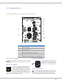
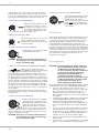
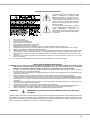
D 8A
ACTIVE FULLRANGE CABINET
Owner‘s Manual | Bedienungsanleitung | Mode d‘emploi
D 8A
CONTENTS
INTRODUCTION . . . . . . . . . . . . . . . . . . . . . . . . . . . . . . . . . . . . . . . . . . . . . . . . . . . . . . . . . . . . . . . . . . . . . . .
Scope of Delivery, Unpacking and Inspection . . . . . . . . . . . . . . . . . . . . . . . . . . . . . . . . . . . . . . . . . .
Warranty . . . . . . . . . . . . . . . . . . . . . . . . . . . . . . . . . . . . . . . . . . . . . . . . . . . . . . . . . . . . . . . . . . . . . . .
INSTALLATION . . . . . . . . . . . . . . . . . . . . . . . . . . . . . . . . . . . . . . . . . . . . . . . . . . . . . . . . . . . . . . . . . . . . . . . .
Controls, Indicators and Connections . . . . . . . . . . . . . . . . . . . . . . . . . . . . . . . . . . . . . . . . . . . . . . . .
Cooling . . . . . . . . . . . . . . . . . . . . . . . . . . . . . . . . . . . . . . . . . . . . . . . . . . . . . . . . . . . . . . . . . . . . . . . .
System Setup . . . . . . . . . . . . . . . . . . . . . . . . . . . . . . . . . . . . . . . . . . . . . . . . . . . . . . . . . . . . . . . . . . .
Rigging . . . . . . . . . . . . . . . . . . . . . . . . . . . . . . . . . . . . . . . . . . . . . . . . . . . . . . . . . . . . . . . . . . . . . . . .
SPECIFICATIONS . . . . . . . . . . . . . . . . . . . . . . . . . . . . . . . . . . . . . . . . . . . . . . . . . . . . . . . . . . . . . . . . . . . . . .
Block Diagram . . . . . . . . . . . . . . . . . . . . . . . . . . . . . . . . . . . . . . . . . . . . . . . . . . . . . . . . . . . . . . . . . . .
Frequency Response . . . . . . . . . . . . . . . . . . . . . . . . . . . . . . . . . . . . . . . . . . . . . . . . . . . . . . . . . . . . .
Beamwidth . . . . . . . . . . . . . . . . . . . . . . . . . . . . . . . . . . . . . . . . . . . . . . . . . . . . . . . . . . . . . . . . . . . . .
Directivity . . . . . . . . . . . . . . . . . . . . . . . . . . . . . . . . . . . . . . . . . . . . . . . . . . . . . . . . . . . . . . . . . . . . . .
Dimensions . . . . . . . . . . . . . . . . . . . . . . . . . . . . . . . . . . . . . . . . . . . . . . . . . . . . . . . . . . . . . . . . . . . . .
Setup Example . . . . . . . . . . . . . . . . . . . . . . . . . . . . . . . . . . . . . . . . . . . . . . . . . . . . . . . . . . . . . . . . . .
....
....
....
....
....
....
....
....
....
....
....
....
....
....
....
. .4
. .4
. .4
. .5
. .5
. .6
. .6
. .7
. .20
. .21
. .21
. .21
. .22
. .23
. .23
....
....
....
....
....
....
....
....
....
....
....
....
....
....
....
. .10
. .10
. .10
. .11
. .11
. .12
. .12
. .13
. .20
. .21
. .21
. .21
. .22
. .23
. .23
....
....
....
....
....
....
....
....
....
....
....
....
....
....
....
. .16
. .16
. .16
. .17
. .17
. .18
. .18
. .19
. .20
. .21
. .21
. .21
. .22
. .23
. .23
INHALT
EINFÜHRUNG . . . . . . . . . . . . . . . . . . . . . . . . . . . . . . . . . . . . . . . . . . . . . . . . . . . . . . . . . . . . . . . . . . . . . . . . .
Lieferumfang, Auspacken und Überprüfen . . . . . . . . . . . . . . . . . . . . . . . . . . . . . . . . . . . . . . . . . . . . .
Garantie . . . . . . . . . . . . . . . . . . . . . . . . . . . . . . . . . . . . . . . . . . . . . . . . . . . . . . . . . . . . . . . . . . . . . . .
INSTALLATION . . . . . . . . . . . . . . . . . . . . . . . . . . . . . . . . . . . . . . . . . . . . . . . . . . . . . . . . . . . . . . . . . . . . . . . .
Bedienelemente, Anzeigen und Anschlüsse . . . . . . . . . . . . . . . . . . . . . . . . . . . . . . . . . . . . . . . . . . . .
Kühlung . . . . . . . . . . . . . . . . . . . . . . . . . . . . . . . . . . . . . . . . . . . . . . . . . . . . . . . . . . . . . . . . . . . . . . . .
Quickstart . . . . . . . . . . . . . . . . . . . . . . . . . . . . . . . . . . . . . . . . . . . . . . . . . . . . . . . . . . . . . . . . . . . . . .
Rigging . . . . . . . . . . . . . . . . . . . . . . . . . . . . . . . . . . . . . . . . . . . . . . . . . . . . . . . . . . . . . . . . . . . . . . . .
SPECIFICATIONS . . . . . . . . . . . . . . . . . . . . . . . . . . . . . . . . . . . . . . . . . . . . . . . . . . . . . . . . . . . . . . . . . . . . . .
Block Diagram . . . . . . . . . . . . . . . . . . . . . . . . . . . . . . . . . . . . . . . . . . . . . . . . . . . . . . . . . . . . . . . . . . .
Frequency Response . . . . . . . . . . . . . . . . . . . . . . . . . . . . . . . . . . . . . . . . . . . . . . . . . . . . . . . . . . . . .
Beamwidth . . . . . . . . . . . . . . . . . . . . . . . . . . . . . . . . . . . . . . . . . . . . . . . . . . . . . . . . . . . . . . . . . . . . .
Directivity . . . . . . . . . . . . . . . . . . . . . . . . . . . . . . . . . . . . . . . . . . . . . . . . . . . . . . . . . . . . . . . . . . . . . .
Dimensions . . . . . . . . . . . . . . . . . . . . . . . . . . . . . . . . . . . . . . . . . . . . . . . . . . . . . . . . . . . . . . . . . . . . .
Setup Example . . . . . . . . . . . . . . . . . . . . . . . . . . . . . . . . . . . . . . . . . . . . . . . . . . . . . . . . . . . . . . . . . .
SOMMAIRE
INTRODUCTION . . . . . . . . . . . . . . . . . . . . . . . . . . . . . . . . . . . . . . . . . . . . . . . . . . . . . . . . . . . . . . . . . . . . . . .
Produit livré et, Déballage et inspection . . . . . . . . . . . . . . . . . . . . . . . . . . . . . . . . . . . . . . . . . . . . . .
Conditions de garantie . . . . . . . . . . . . . . . . . . . . . . . . . . . . . . . . . . . . . . . . . . . . . . . . . . . . . . . . . . . .
INSTALLATION . . . . . . . . . . . . . . . . . . . . . . . . . . . . . . . . . . . . . . . . . . . . . . . . . . . . . . . . . . . . . . . . . . . . . . . .
Contrôles, Indicateurs et Connexions . . . . . . . . . . . . . . . . . . . . . . . . . . . . . . . . . . . . . . . . . . . . . . . .
Ventilation . . . . . . . . . . . . . . . . . . . . . . . . . . . . . . . . . . . . . . . . . . . . . . . . . . . . . . . . . . . . . . . . . . . . . .
Réglage du système . . . . . . . . . . . . . . . . . . . . . . . . . . . . . . . . . . . . . . . . . . . . . . . . . . . . . . . . . . . . . .
Suspension . . . . . . . . . . . . . . . . . . . . . . . . . . . . . . . . . . . . . . . . . . . . . . . . . . . . . . . . . . . . . . . . . . . . .
SPECIFICATIONS . . . . . . . . . . . . . . . . . . . . . . . . . . . . . . . . . . . . . . . . . . . . . . . . . . . . . . . . . . . . . . . . . . . . . .
Block Diagram . . . . . . . . . . . . . . . . . . . . . . . . . . . . . . . . . . . . . . . . . . . . . . . . . . . . . . . . . . . . . . . . . . .
Frequency Response . . . . . . . . . . . . . . . . . . . . . . . . . . . . . . . . . . . . . . . . . . . . . . . . . . . . . . . . . . . . .
Beamwidth . . . . . . . . . . . . . . . . . . . . . . . . . . . . . . . . . . . . . . . . . . . . . . . . . . . . . . . . . . . . . . . . . . . . .
Directivity . . . . . . . . . . . . . . . . . . . . . . . . . . . . . . . . . . . . . . . . . . . . . . . . . . . . . . . . . . . . . . . . . . . . . .
Dimensions . . . . . . . . . . . . . . . . . . . . . . . . . . . . . . . . . . . . . . . . . . . . . . . . . . . . . . . . . . . . . . . . . . . . .
Setup Example . . . . . . . . . . . . . . . . . . . . . . . . . . . . . . . . . . . . . . . . . . . . . . . . . . . . . . . . . . . . . . . . . .
2
D 8A
IMPORTANT SAFETY INSTRUCTIONS
The lightning flash with arrowhead symbol, within an equilateral
triangle is intended to alert the user to the presence of uninsulated
”dangerous voltage” within the product’s enclosure that may be of
sufficent magnitude to constitute a risk of electric shock to persons.
The exclamation point within an equilateral triangle is intended to
alert the user to the presence of important operating and
maintance (servicing) instructions in the literature accompanying
the appliance.
1.
2.
3.
4.
5.
6.
7.
8.
9.
10.
11.
12.
13.
14.
15.
16.
17.
18.
19.
Read these instructions.
Keep these instructions.
Heed all warnings.
Follow all instructions.
Do not use this apparatus near water.
Clean only with a dry cloth.
Do not cover any ventilation openings. Install in accordance with the manufacturer’s instructions.
Do not install near heat sources such as radiators, heat registers, stoves, or other apparatus (including amplifiers) that produce heat.
Do not defeat the safety purpose of the polarized or the grounding-type plug. A polarized plug has two blades with one wider than the other. A grounding type plug has two
blades and a third grounding prong. The wide blade or the third prong are provided for your safety. If the provided plug does not fit into your outlet, consult an electrician
for replacement of the obsolete outlet.
Protect the power cord from being walked on or pinched particularly at plugs, convenience receptacles, and the point where they exit from the apparatus.
Only use attachments/accessories specified by the manufacturer.
Use only with the cart, tripod, bracket, or table specified by the manufacturer, or sold with the apparatus. When a cart is used, use caution when moving
the cart/apparatus combination to avoid injury from tip-over.
Unplug this apparatus during lightning storms or when unused for a long period of time.
Refer all servicing to qualified service personnel. Servicing is required when the apparatus has been damaged in any way, such as power-supply cord or
plug is damaged, liquid has been spilled or orbjects have fallen into the apparatus, the apparatus has been exposed to rain or moisture, does not operate
normally, or has been dropped.
Do not expose this equipment to dripping or splashing and ensure that no objects filled with liquids, such as vases, are placed on the equipment.
To completely disconnect this equipment from the AC Mains, disconnect the power supply cord plug from the AC receptacle.
The mains plug of the power supply cord shall remain readily operable.
No naked flame sources, such as lighted candles, should be placed on the apparatus.
The product should be connected to a mains socket outlet with a protective earthing connection.
IMPORTANT SERVICE INSTRUCTIONS
CAUTION: These servicing instructions are for use by qualified personnel only. To reduce the risk of electric shock, do not
perform any servicing other than that contained in the Operating Instructions unless you are qualified to do so. Refer
all servicing to qualified service personnel.
1.
2.
3.
4.
5.
6.
7.
8.
Security regulations as stated in the EN 60065 (VDE 0860 / IEC 65) and the CSA E65 - 94 have to be obeyed when servicing the appliance.
Use of a mains separator transformer is mandatory during maintenance while the appliance is opened, needs to be operated and is connected to the mains.
Switch off the power before retrofitting any extensions, changing the mains voltage or the output voltage.
The minimum distance between parts carrying mains voltage and any accessible metal piece (metal enclosure), respectively between the mains poles has to be 3 mm and
needs to be minded at all times. The minimum distance between parts carrying mains voltage and any switches or breakers that are not connected to the mains
(secondary parts) has to be 6 mm and needs to be minded at all times.
Replacing special components that are marked in the circuit diagram using the security symbol (Note) is only permissible when using original parts.
Altering the circuitry without prior consent or advice is not legitimate.
Any work security regulations that are applicable at the locations where the appliance is being serviced have to be strictly obeyed. This applies also to any regulations
about the work place itself.
All instructions concerning the handling of MOS-circuits have to be observed.
NOTE:
SAFETY COMPONENT (MUST BE REPLACED BY ORIGINAL PART)
WEEE RECYCLING/DISPOSAL INSTRUCTIONS
The Wheelie Bin symbol found on the product or in the manual indicates that this product must not be disposed of with other waste. It is in our category the
manufacturer’s responsibility to properly dispose of their waste electrical and electronic equipment (WEEE) at the end of its life. Due to the differences in each EU
country’s management of WEEE, please contact your local distributor. We are committed to facilitate our own electronic-waste-management-system, for the free of
charge return of all EVI Audio GmbH products: Telex, DYNACORD, Electro-Voice and RTS. Arrangements are made with the dealer where you purchased the
equipment from, for the returning of all unusable equipment at no cost, to the factory in Straubing, for environmental protective disposal.
3
D 8A
1 Introduction
The DYNACORD D 8A is a powered, biamped, light-weight
and extremely robust high-performance professional 8” 2way plastic cabinet for use in professional sound
reinforcement applications. With a variety of suspension
accessories and conservative cosmetics, the D 8A is also
ideally suited to be used in demanding fixed installations.
The cabinet is manufactured from ABS and therefore is extremely resistant against abuse on the road. For low frequencies a DYNACORD DND8200-8 is used. The ElectroVoice DH 3 driver is used for the projection of mid and high
frequencies. The Constant-Directivity HF horn has been integrated into the baffle by CAD methods. Nominal coverage angle of the cabinet is 90° * 90°, horizontal * vertical
respectively.
The built-in digital power amplifiers are working in biamped operation and are controlled by an electronic x-over
circuit that has been designed to optimally match the
transducers’ acoustic characteristics. The D 8A is ideally
suited for applications as full-range cabinet or as Mid-Hi
cabinet in high-performance satellite systems. EASE and
ULYSSES data allow fast and precise simulations.
The line-level input signal can be connected to the cabinet
by means of an XLR plug or a standard phone plug. Additionally an microphone level input signal can be connected
by means of an XLR plug and adjusted using the microphone level control MIC. The master signal can be daisychained to a second D 8A cabinet via a regular XLR microphone cable. The built-in level control MASTER allows easy
adjustment of the required sound pressure level.
The D 8A is connected to the mains via a locked IEC inlet
that guarantees a hassle-free operation. Extremely durable
acoustic foam mounted to a strong powder-coated steel
grille protects the loudspeaker components against any
mechanical damage. A protective cover is available as an
option.
Packing the cabinet like it was packed by the manufacturer
guarantees optimum protection from transport damage.
1.2 Warranty
Keep the original invoice that states the purchase/delivery
date together with the warranty certificate at a safe place.
The manufacturer‘s warranty covers all substantial defects
in materials and workmanship for a period of 36 months
from the date of purchase. Liability claims are accepted
solely, when a valid - correctly and completely filled out Warranty Registration Form is presented by the original
owner of the product. The warranty does not cover
damage that results from improper or inadequate treatment or maintenance. In case of alteration or unauthorized
repairs, the warranty is automatically terminated.
HINT: This equipment has been tested and found to
comply with the limits for a Class A digital
device, pursuant to Part 15 of the FCC Rules.
These limits are designed to provide reasonable
protection against harmful interference when the
equipment is operated in a commercial environment. This equipment generates, uses, and can
radiate radio frequency energy and, if not
installed and used in accordance with the
instruction manual, may cause harmful interference to radio communications. Operation of this
equipment in a residental area is likely to cause
harmful interference in which case the user will
be required to correct the interference at his
own expense.
NOTES:
1.1 Scope of Delivery, Unpacking and
Inspection
•
•
•
•
1 Active Cabinet
1 Owner‘s Manual (this document)
1 Mains Cord (5 meters)
1 Warranty Certificate including Safety Instructions
Carefully open the packaging and take out the cabinet. Inspect the cabinet’s enclosure for damages that might have
occured during transportation. Each cabinet is examined
and tested in detail before leaving the manufacturing site
to ensure that it arrives in perfect condition at your place.
Please inform the transport company immediately if the
cabinet shows any damage. Being the addressee, you are
the only person who can claim damages in transit. Keep
the cardboard box and all packaging materials for inspection by the transport company.
Keeping the cardboard box including all packing materials
is also recommended, if the cabinet shows no external
damages.
CAUTION:
4
Do not ship the cabinet in any other than its
original packaging.
This equipment has been tested and found to
comply pursuant to the product family
standard for audio professional use according
EMC Directive 2004/108/EC: EN55103-1 and
EN55013-2 standards (with the limits for E4
and E5 electromagnetic environment);
EN61000-3-2, EN61000-3-3.
D 8A
2 Installation
2.1 Controls, Indicators and Connections
4
5
6
1
7
2
8
LO-CUT
9
3
10
Number
Description
1
Power on/off indicator (POWER)
2
Mains switch (ON / OFF)
3
Mains connector, lockable (MAINS IN)
4
Limit indicator (LIMIT)
5
Master level control (MASTER)
6
Microphone level control (MIC)
7
Input connector for microphone level audio signal (MIC IN)
8
Mode selection switch (LO-CUT / FULLRANGE)
9
Input connector (XLR or phone) for line level audio signal (LINE IN)
10
Output connector for line level audio signal (MASTER OUT)
1 POWER ON/OFF INDICATOR (POWER)
3 MAINS CONNECTOR (MAINS IN)
The POWER LED lights green if the mains switch
is ON and the mains cord is connected correctly.
The D 8A receives its power supply
via the mains input. A suitable 5 meters long mains cord is supplied.
2 MAINS SWITCH (ON/OFF)
Mains switch for switching the unit‘s power
ON or OFF. The POWER LED lights after
turning the power ON. Make sure that the
mains cord is correctly connected if the LED
is not lit upon turning the power on. If the
mains cord is correctly connected, mains
voltage is present and the LED does not light upon poweron, please contact your local dealer.
CAUTION:
This applicance has no user-servicable parts
inside. Leave any servicing and maintenance
to qualified service technicians only.
5
D 8A
4 LIMIT INDICATOR (LIMIT)
10 OUTPUT CONNECTOR (MASTER OUT)
Brief blinking of the LIMIT LED indicates that the
power amplifier of the D 8A is operated at its limits.
Short-term blinking is uncritical, because the integrated limiter compensates minor distortion. Constant lighting of the LED indicates that the sound is negatively
affected. Reducing the output volume is strongly recommended.
The output connector provides the
Master Signal (Line+Mic) for ”carrying through“ the input signal. The
level of the output signal is independent of the setting of the Master level control (”Pre Fader”).
5 MASTER LEVEL CONTROL (MASTER)
Level control for adjusting the
power amp’s overall amplification.
6 MICROPHONE LEVEL CONTROL (MIC)
Level control for adjusting the amplification of the signal at the MIC IN input.
2.2 Cooling
This is a powered speaker with a very high efficient amplifier module and as a result does not get really hot. The
temperature of the amplifier module is monitored. In the
rare event it does get too hot it will automatically shut
down to protect itself. Once its temperature has returned
to within its operating range the amp will turn back on.
This may happen when the speaker is operated in very high
ambient temperatures and the enclosure is exposed to direct sunlight. Always ensure adequate cooling and appropriate shade to keep the ambient temperature around the
product within the specified operating temperature range.
7 INPUT CONNECTOR FOR MICROPHONE AUDIO SIGNAL (MIC IN)
Audio input for connecting an
balanced audio signal with microphone level.
2.3 System Setup
CAUTION:
CAUTION:
Before making any connections or disconnections, make sure to set the level control
to the counterclockwise stop.
8 MODE SELECTION SWITCH (LO-CUT/FULLRANGE)
LO-CUT
If the D 8A is used as a fullrange system, select FULLRANGE (button not
pressed).
If a subwoofer without a low-cut signal output is used, i.e.
the identical audio signal is used for the D 8A and the
subwoofer, select LO-CUT (button pressed) for activating
the internal low-cut filter of the D 8A. If the D 8A is connected to the HI OUT output of a subwoofer with integrated low-cut filter, select FULLRANGE to avoid having the
two low-cut filters of the subwoofer and D 8A in series.
The setting LO-CUT can also be used for monitor or delay
applications, when a high bass level is not necessary.
9 INPUT CONNECTOR FOR AUDIO SIGNAL (LINE IN)
Electronically balanced input for the
connection of a line level signal source such as mixer, signal processor,
etc. Establishing a connection is possible via phone or XLR-type plugs.
Whenever possible, balanced signal
feed is always preferable to guard against potential noise
or HF-interference.
CAUTION:
6
Before making any connections or disconnections, make sure to set the level control
to the counterclockwise stop.
After installing the system, first switch on
the mixing console and position the mixer’s
master faders to their minimum settings.
That followed, switch on the D 8A and use
the MASTER to adjust the desired volume
setting. Otherwise, high sound levels
caused by unintentional playback of a program source could be the result, which
might cause hearing damage.
This Quick Start Manual outlines setup and operation of
the D 8A connected to a DYNACORD CMS mixer.
1.
Place the D 8A, mounted on pole-mount stands to
the left and to the right. The lower edges of the
speaker systems should be approximately 1,8 meters
above the audience to provide sufficient coverage
and to prevent that listeners nearby are subject to
extreme sound levels.
2.
Using suitable XLR-type cables connect the Master
Outputs of your mixing console, e.g. DYNACORD
CMS 1000, to LINE IN of the D 8A. Position the master faders on the mixer to their minimum setting.
Now, switch on the mixer.
3.
Connect the D 8A to the mains outlet using the supplied mains cord. Plug the connector into the MAINS
IN socket. Use the Mains switch to power-up the
D 8A.
4.
Set the level control MASTER of the D 8A to 0dB.
5.
Connect a audio source, e.g. CD player, to a line level
input of the mixer, e.g. CMS 1000. Set all rotary
controls of the mixing console input channel to their
center position. Adjust the input channel’s ‘Gain‘
control so that the Peak LED should not light at all or
blink only once in a while.
6.
Slowly raise channel fader and master faders on the
mixing console to the desired positions – i.e. volume
settings.
D 8A
7.
8.
Your system is now ready for operation. Individual
sound adjustments necessary can be made using the
controls of the mixer’s corresponding input
channels.
Now, have fun with your D 8A system!
9.
After use, first switch off the D 8A and then the
mixing console, so that distracting power-off noise
will not occur. When using a DYNACORD CMS mixer,
no power-off noise will be output from the ‘Master
Outputs‘. This allows switching off the mixer first
without a problem.
2.4 Rigging
CAUTION:
We expressly point out that the relevant safety regulations must be observed for “flying“ loudspeaker
systems. It is imperative that qualified expert advice is sought.
CAUTION:
Suspending any object is potentially dangerous and should only be attempted by individuals who have
a thorough knowledge of the techniques and regulations of rigging objects overhead. Dynacord
strongly recommends that D 8A speakers be suspended taking into account all current national, federal, state and local regulations. It is the responsibility of the installer to ensure that D 8A speakers are
safely installed in accordance with all such regulations. If D 8A speakers are suspended, Dynacord
strongly recommends that the system be inspected at least once a year. If any sign of weakness or damage is detected, remedial action should be taken immediately.
Order No. see Specifications (page 20)
FB-D8
FB-D8 + PCL-M10
FB-D8 + FB-TV
FB-D8 + TC-02
FB-D8 + FB-TV
+ TC-TV
FB-D8 + FB-TV
+ PM-TV
WMK-10
MB-D8 UMH
MB-D8 UMH
+ TC-02
MB-D8 UMH
+ RMA +TMA
7
D 8A
8
D 8A
WICHTIGE SICHERHEITSHINWEISE
Das Blitzsymbol innerhalb eines gleichseitigen
Dreiecks soll den Anwender auf nicht isolierte Leitungen und Kontakte im Geräteinneren hinweisen,
an denen hohe Spannungen anliegen, die im Fall
einer Berührung zu lebensgefährlichen Stromschlägen führen können.
Das Ausrufezeichen innerhalb eines gleichseitigen
Dreiecks soll den Anwender auf wichtige Bedienungs- sowie Servicehinweise in der zum Gerät
gehörenden Literatur aufmerksam machen.
1.
2.
3.
4.
5.
6.
7.
8.
9.
10.
11.
12.
13.
14.
15.
16.
17.
18.
19.
Lesen Sie diese Hinweise.
Heben Sie diese Hinweise auf.
Beachten Sie alle Warnungen.
Richten Sie sich nach den Anweisungen.
Betreiben Sie das Gerät nicht in unmittelbarer Nähe von Wasser.
Verwenden Sie zum Reinigen des Gerätes ausschließlich ein trockenes Tuch.
Verdecken Sie keine Lüftungsschlitze. Beachten Sie bei der Installation des Gerätes stets die entsprechenden Hinweise des Herstellers.
Vermeiden Sie die Installation des Gerätes in der Nähe von Heizkörpern, Wärmespeichern, Öfen oder anderer Wärmequellen.
Achtung: Gerät nur an Netzsteckdose mit Schutzleiteranschluss betreiben. Setzen Sie die Funktion des Schutzleiteranschlusses des
mitgelieferten Netzanschlusskabels nicht außer Kraft. Sollte der Stecker des mitgelieferten Kabels nicht in Ihre Netzsteckdose passen, setzen
Sie sich mit Ihrem Elektriker in Verbindung.
Sorgen Sie dafür, dass das Netzkabel nicht betreten wird. Schützen Sie das Netzkabel vor Quetschungen insbesondere am Gerätestecker und
am Netzstecker.
Verwenden Sie mit dem Gerät ausschließlich Zubehör/Erweiterungen, die vom Hersteller hierzu vorgesehen sind.
Verwenden Sie zusammen mit dieser Komponente nur vom Hersteller dazu vorgesehene oder andere geeignete Lastkarren,
Stative, Befestigungsklammern oder Tische, die Sie zusammen mit dem Gerät erworben haben. Achten Sie beim Transport mittels
Lastkarren darauf, dass das transportierte Equipment und der Karren nicht umfallen und möglicherweise Personen- und/oder
Sachschäden verursachen können.
Ziehen Sie bei Blitzschlaggefahr oder bei längerem Nichtgebrauch den Netzstecker.
Überlassen Sie sämtliche Servicearbeiten und Reparaturen einem ausgebildeten Kundendiensttechniker. Servicearbeiten sind
notwendig, sobald das Gerät auf irgendeine Weise beschädigt wurde, wie z.B. eine Beschädigung des Netzkabels oder des Netzsteckers, wenn
eine Flüssigkeit in das Gerät geschüttet wurde oder ein Gegenstand in das Gerät gefallen ist, wenn das Gerät Regen oder Feuchtigkeit
ausgesetzt wurde, oder wenn es nicht normal arbeitet oder fallengelassen wurde.
Stellen Sie bitte sicher, dass kein Tropf- oder Spritzwasser ins Geräteinnere eindringen kann. Platzieren Sie keine mit Flüssigkeiten gefüllten
Objekte, wie Vasen oder Trinkgefäße, auf dem Gerät.
Um das Gerät komplett spannungsfrei zu schalten, muss der Netzstecker gezogen werden.
Beim Einbau des Gerätes ist zu beachten, dass der Netzstecker leicht zugänglich bleibt.
Stellen Sie keine offenen Brandquellen, wie z.B. brennende Kerzen auf das Gerät.
Dieses SCHUTZKLASSE I Gerät muss an eine NETZ-Steckdose mit Schutzleiter-Anschluss angeschlossen werden.
WICHTIGE SERVICEHINWEISE
ACHTUNG: Diese Servicehinweise sind ausschließlich zur Verwendung durch qualifiziertes Servicepersonal. Um die Gefahr
eines elektrischen Schlages zu vermeiden, führen Sie keine Wartungsarbeiten durch, die nicht in der
Bedienungsanleitung beschrieben sind, außer Sie sind hierfür qualifiziert. Überlassen Sie sämtliche
Servicearbeiten und Reparaturen einem ausgebildeten Kundendiensttechniker.
1.
2.
3.
4.
5.
6.
7.
8.
9.
Bei Reparaturarbeiten im Gerät sind die Sicherheitsbestimmungen nach EN 60065 (VDE 0860) einzuhalten.
Bei allen Arbeiten, bei denen das geöffnete Gerät mit Netzspannung verbunden ist und betrieben wird, ist ein Netz-Trenntransformator zu
verwenden.
Vor einem Umbau mit Nachrüstsätzen, Umschaltung der Netzspannung oder sonstigen Modifikationen ist das Gerät stromlos zu schalten.
Die Mindestabstände zwischen netzspannungsführenden Teilen und berührbaren Metallteilen (Metallgehäuse) bzw. zwischen den Netzpolen
betragen 3 mm und sind unbedingt einzuhalten.
Die Mindestabstände zwischen netzspannungsführenden Teilen und Schaltungsteilen, die nicht mit dem Netz verbunden sind (sekundär),
betragen 6 mm und sind unbedingt einzuhalten.
Spezielle Bauteile, die im Stromlaufplan mit dem Sicherheitssymbol gekennzeichnet sind, (Note) dürfen nur durch Originalteile ersetzt werden.
Eigenmächtige Schaltungsänderungen dürfen nicht vorgenommen werden.
Die am Reparaturort gültigen Schutzbestimmungen der Berufsgenossenschaften sind einzuhalten. Hierzu gehört auch die Beschaffenheit des
Arbeitsplatzes.
Die Vorschriften im Umgang mit MOS-Bauteilen sind zu beachten.
NOTE:
SAFETY COMPONENT (MUST BE REPLACED BY ORIGINAL PART)
Hinweise zur Entsorgung/Wiederverwendung gemäß WEEE
Das auf unserem Produkt und im Handbuch abgedruckte Mülltonnensymbol weist daraufhin, dass dieses Produkt nicht gemeinsam mit dem Haushaltsmüll entsorgt werden darf. Für
die korrekte Entsorgung der Elektro- und Elektronik-Altgeräte (WEEE) am Ende ihrer Nutzungsdauer ist in unserer Kategorie der Hersteller verantwortlich. Aufgrund
unterschiedlicher Regelungen zur WEEE-Umsetzung in den einzelnen EU-Staaten bitten wir Sie, sich an Ihren örtlichen Händler zu wenden. Wir haben ein eigenes System zur
Verarbeitung elektronischer Abfälle und gewährleisten die kostenfreie Entgegennahme aller Produkte der EVI Audio GmbH: Telex, DYNACORD Electro-Voice und RTS. Wir haben mit
dem Händler, bei dem Sie Ihr Produkt gekauft haben, eine Vereinbarung getroffen, dass alle nicht mehr verwendbaren Geräte zur umweltgerechten Entsorgung kostenfrei an das
Werk in Straubing zurückgeschickt werden.
9
D 8A
1 Einführung
Die DYNACORD D 8A ist ein extrem leichtes, mechanisch
robustes, aktives 8“ 2-Weg Kunststoffkabinett mit
eingebauten Leistungsendstufen für professionelle Beschallungsanwendungen. Umfangreiches Montagezubehör
und eine zurückhaltende optische Gestaltung des
Kabinetts ermöglichen den problemlosen Einsatz auch in
kritischen Anwendungen für Festinstallationen. Das
Gehäuse ist aus ABS gefertigt und widersteht härtesten
Anforderungen bei Transport und Einsatz. Die D 8A ist mit
dem DYNACORD DND8200-8 Lautsprecher für den Bassund Mittenbereich ausgestattet. Das Constant Directivity
Hochtonhorn mit nominalen Abstrahlwinkeln von 90° * 90°
(Horizontal * Vertikal) ist CAD-optimiert in die Schallwand
integriert und mit dem hochbelastbaren DH 3 Treiber von
Electro-Voice ausgestattet.
Die eingebauten Digitalendstufen arbeiten im Aktiv-2-Weg
Betrieb und werden von einer speziell auf die Lautsprecherkomponenten ausgelegten elektronischen Frequenzweiche angesteuert. Mit einem Maximalschallpegel
von 123 dB (1 kHz, k = 10%) und einem Übertragungsbereich von 65 Hz bis 20 kHz eignet sich die D 8A hervorragend sowohl als Fullrange Kabinett als auch als MittelHochtonteil in Satellitensystemen. Die aktive Frequenzweiche ist auf große Reichweite bei gleichmäßiger
Abstrahlcharakteristik hin optimiert und gestattet den
Einsatz der D 8A auch unter ungünstigen akustischen
Umgebungsbedingungen. Mit den EASE und Ulysses Datenfiles sind problemlos auch anspruchsvollste Simulationen schnell und präzise durchführbar.
Das Eingangssignal mit Line-Pegel kann sowohl über einen
XLR-Stecker als auch über einen Klinkenstecker zugeführt
werden. Zusätzlich kann ein Eingangssignal mit MikrofonPegel über einen XLR-Stecker angeschlossen werden, für
die Pegelanpassung des Mikrofonsignals wird der zugehörige Pegelregler MIC verwendet. Das Gesamtsignal kann
über ein XLR-Kabel auf weitere D 8A Boxen weitergeschleift werden. Der Pegelregler MASTER gestattet eine
einfache Lautstärkeanpassung des widergegebenen Gesamtsignals.
Die D 8A wird über einen verriegelten Stecker an das
Stromnetz angeschlossen. Die Frontabdeckung ist in
schwarzem Akustikschaum auf einem robusten, pulverbeschichtetem Stahlgitter ausgeführt. Als Zubehör ist eine
robuste, strapazierfähige und wasserabweisende Schutzhülle erhältlich.
1.1 Lieferumfang, Auspacken und
Überprüfen
•
•
•
•
1 Aktives Kabinett
1 Bedienungsanleitung (dieses Dokument)
1 Netzkabel (5 Meter)
1 Garantiekarte mit Sicherheitshinweisen
Öffnen Sie die Verpackung und entnehmen Sie das
Kabinett. Überprüfen Sie das Kabinett auf äußere Beschädigungen, die während des Transports zu Ihnen aufgetreten sein könnten. Jedes Kabinett wird vor Verlassen des
Werks eingehend untersucht und getestet und sollte in einwandfreiem Zustand bei Ihnen ankommen. Falls das
Kabinett Beschädigungen aufweist, benachrichtigen Sie
10
bitte unverzüglich das Transportunternehmen. Ein
Transportschaden kann nur von Ihnen, dem Empfänger,
reklamiert werden. Bewahren Sie den Karton und das Verpackungsmaterial zwecks Besichtigung durch das
Transportunternehmen auf. Die Aufbewahrung des Kartons samt Verpackungsmaterial wird auch dann angeraten,
wenn das Kabinett keine Beschädigung aufweist.
ACHTUNG: Versenden Sie das Kabinett nie ohne das
originale Verpackungsmaterial.
Für bestmöglichen Schutz vor Transportschäden verpakken Sie das Kabinett wie es ursprünglich im Werk verpackt
wurde.
1.2 Garantie
Bewahren Sie neben der Garantiekarte auch den
Kaufbeleg, der den Termin der Übergabe festlegt, auf.
Das Werk leistet Garantie für alle nachweisbaren Materialund Fertigungsfehler für die Dauer von 36 Monaten ab Verkauf. Garantieleistungen werden nur dann anerkannt,
wenn gültige, d.h. vollständig ausgefüllte Garantieunterlagen vorliegen. Von der Garantie ausgenommen sind alle
Schäden, die durch falsche oder unsachgemäße Bedienung verursacht werden. Bei Fremdeingriffen oder
eigenmächtigen Änderungen erlischt jeder Garantieanspruch.
D 8A
2 Installation
2.1 Bedienelemente, Anzeigen und Anschlüsse
4
5
6
1
7
2
8
LO-CUT
9
3
10
Nummer
Beschreibung
1
Anzeige Betrieb (POWER)
2
Netzschalter (ON / OFF)
3
Netzeingang, verriegelnd (MAINS IN)
4
Anzeige Limiter (LIMIT)
5
Eingangspegel-Regler (MASTER)
6
Mikrofonpegel-Regler (MIC)
7
Eingang für Audio-Signal mit Mikrofon-Pegel (MIC IN)
8
Schalter für Betriebsart (LO-CUT / FULLRANGE)
9
Eingang (XLR/Klinke) für Audio-Signal mit Line-Pegel (LINE IN)
10
Ausgang für (gemischtes) Audio-Signal mit Line-Pegel (MASTER OUT)
1 ANZEIGE BETRIEB (POWER)
Die POWER-LED leuchtet grün, wenn die D 8A
mit dem Stromnetz verbunden und eingeschaltet (ON) ist.
3 NETZEINGANG (MAINS IN)
Die Spannungsversorgung der D 8A
erfolgt über die Netzeingangsbuchse.
Ein passendes, 5 Meter langes Netzkabel ist im Lieferumfang enthalten.
2 NETZSCHALTER (ON/OFF)
Netzschalter zum Ein- und Ausschalten des
Gerätes. Die POWER-LED leuchtet grün
wenn die D 8A eingeschaltet ist. Sollte die
LED nach dem Einschalten nicht leuchten,
prüfen Sie zuerst ob das Netzkabel angesteckt und Netzspannung vorhanden ist. Ist
dies der Fall und trotzdem keine Funktion vorhanden, kontaktieren Sie bitte ihren Fachhändler.
4 ANZEIGE LIMITER (LIMIT)
Die LIMIT-LED zeigt beim Aufleuchten an, dass der interne Leistungsverstärker aktuell im Grenzbereich
der Aussteuerbarkeit betrieben wird. Kurzzeitiges
Aufleuchten ist unkritisch, da der Audio-Limiter im Leis-
11
D 8A
tungsverstärker die Verzerrungen ausregelt. Dauerndes
Aufleuchten deutet auf eine Übersteuerung des Verstärkers hin, die zu Klangeinbußen führen kann und durch Absenkung des Eingangspegels vermieden werden sollte.
10 AUSGANG FÜR AUDIO-SIGNAL (MASTER OUT)
Am Ausgang MASTER OUT liegt das
gemischte Signal des LINE- und
MIC-Eingangs zum „Weiterschleifen” an. Der Pegel des Signals
hängt nicht von der Stellung des
Eingangspegel-Regler MASTER ab
(„Pre Fader“).
5 EINGANGSPEGEL-REGLER (MASTER)
Mit diesem Regler stellen Sie die
Lautstärke der D 8A ein. Zur Vermeidung von Verzerrungen in vorgeschalteten Mischpulten sollte
dieser Regler normalerweise zwischen 0 dB und +6 dB eingestellt werden.
2.2 Kühlung
6 MIKROFONPEGEL-REGLER (MIC)
Mit diesem Regler passen Sie die Lautstärke des Mikrofon-Signals an. Der
Einstellbereich erstreckt sich dabei von
-∞ dB bis +40 dB.
7 EINGANG FÜR MIKROFON-SIGNAL (MIC IN)
Eingang für ein symmetrisches AudioSignal mit Mikrofon-Pegel.
ACHTUNG: Drehen Sie vor dem An- und Abstecken an
den Eingängen den entsprechenden PegelRegler auf Linksanschlag.
8 SCHALTER FÜR DIE BETRIEBSART (LO-CUT/FULLRANGE)
Wählen Sie die Schalterstellung
FULLRANGE (Schalter nicht gedrückt)
wenn die D 8A ohne Subwoofer betrieben wird.
Bei Verwendung eines zusätzlichen Subwoofers ohne
Weichenausgang (D 8A und Subwoofer mit dem gleichen
NF-Signal parallel angesteuert) aktivieren Sie das interne
Hochpass-Filter der D 8A durch Wahl der Schalterstellung
LO-CUT (Schalter gedrückt). Bei Verwendung eines zusätzlichen Subwoofers mit Weichenausgang (D 8A vom HI-OUT
NF-Signal aus dem Subwoofer angesteuert) ist dagegen
die D 8A in der Schalterstellung FULLRANGE zu betreiben,
da ansonsten zwei Hochpassfilter in Reihe im Signalpfad
liegen würden.
Die Schalterstellung LO-CUT ist auch für Monitor- und
Delay-Anwendungen geeignet, wenn kein hoher Bass-Pegel
benötigt wird.
LO-CUT
9 EINGANG FÜR LINE-SIGNAL (LINE IN)
Elektronisch symmetrische Eingänge
für hochpegelige Signalquellen wie
Mischpult- bzw. Signalprozessorausgänge. Der Anschluss kann dabei
wahlweise über Klinken- oder XLRStecker vorgenommen werden. Um
etwaigen externen Brumm-, oder Hochfrequenzeinstreuungen vorzubeugen, sollte die Signaleinspeisung, wenn
möglich, symmetrisch erfolgen.
ACHTUNG: Drehen Sie vor dem An- und Abstecken an
den Eingängen den entsprechenden PegelRegler auf Linksanschlag.
12
Das in der D 8A integrierte Endstufenmodul hat einen sehr
hohen Wirkungsgrad, daher ist die Wärmeentwicklung
sehr gering. Wird die zulässige Betriebstemperatur der
Endstufe überschritten, schaltet die integrierte Temperaturüberwachung das Modul ab. Sobald die Temperatur wieder im normalen Betriebsbereich liegt geht die
Endstufe automatisch wieder in Betrieb. Zur Abschaltung
kommt es normalerweise nur bei sehr hoher Umgebungstemperatur und direkter Sonneneinstrahlung. Sorgen Sie
daher während des Betriebs der D 8A für die Einhaltung
der spezifizierten Umgebungstemperatur um ein
Abschalten zu verhindern.
2.3 Quickstart
ACHTUNG: Nach dem Aufbau der Anlage schalten Sie
zuerst das Mischpult ein und schieben Sie
die Masterfader am Mischpult auf den
untereren Anschlag. Anschliessend können
Sie die D 8A einschalten und mit dem
Eingangspegel-Regler MASTER die
gewünschte Lautstärke einstellen.
Ansonsten können Sie ungewollt bei eingeschalteter Signalquelle sehr hohen Schallpegeln ausgesetzt werden, die zu
Gehörschädigungen führen können.
Diese Quickstart-Anleitung erklärt Aufbau und Betrieb von
D 8A Kabinetten mit einem DYNACORD CMS Mischpult.
1.
Stellen Sie die D 8A links und rechts auf Hochständer. Die Boxenunterkanten sollten in etwa 1,80
Meter Höhe über dem Publikum sein, um eine
genügende Reichweite zu erzielen und die in der
Nähe befindlichen Zuhörer vor zu hohen Schallpegeln
zu schützen.
2.
Verbinden Sie die Master Outputs Ihres Mischpultes,
z.B. DYNACORD CMS 1000, mit geeigneten XLR
Kabeln mit der Buchse LINE IN der D 8A und
schieben Sie die Masterfader am Mischpult auf den
unteren Anschlag. Schalten Sie nun das Mischpult
ein.
3.
Sie können nun die D 8A mit dem beiliegenden Netzkabel an das Stromnetz anschliessen. Der Stecker
wird hierzu in die Buchse MAINS IN gesteckt bis der
Stecker hör- und spürbar verriegelt. Mit dem Netzschalter setzen Sie die D 8A in Betrieb (ON).
4.
Stellen Sie den Eingangspegel-Regler MASTER der
D 8A auf 0dB.
5.
Schliessen Sie nun eine Audio-Quelle, z. B. einen CDPlayer, an einen LINE-Kanal Ihres Mischpultes, z.B.
D 8A
6.
7.
CMS 1000, an. Justieren Sie den Gain-Regler des
Eingangskanals des Mischpults so, dass die PeakLED im Kanal nicht oder nur gelegentlich aufleuchtet.
Sie können nun den Kanalfader und die Masterfader
am Mischpult langsam auf die gewünschte Lautstärke „hochfahren”.
Ihre Anlage ist damit betriebsbereit und Sie können
individuell notwendige klangliche Korrekturen in den
Eingangskanälen des Mischpultes justieren.
8.
9.
Viel Spass beim Arbeiten mit Ihrer D 8A Anlage!
Nach Benutzung schalten Sie zuerst die D 8A und
anschliessend Ihr Mischpult aus. Störende Abschaltgeräusche können dann nicht auftreten. Bei Verwendung eines DYNACORD CMS Mischpultes treten
an den ‚Master Outputs‘ keinerlei Abschaltgeräusche
auf, hier können Sie bedenkenlos auch das Mischpult
zuerst ausschalten.
2.4 Rigging
ACHTUNG: Wir weisen ausdrücklich darauf hin, dass bei gehängten Lautsprecherboxen die einschlägigen Sicherheitsbestimmungen zu beachten sind. Es muss unbedingt qualifizierte Fachberatung in Anspruch
genommen werden!
Für Bestellnummern des Rigging-Zubehörs siehe Seite 20.
FB-D8
FB-D8 + PCL-M10
FB-D8 + FB-TV
FB-D8 + TC-02
FB-D8 + FB-TV
+ TC-TV
FB-D8 + FB-TV
+ PM-TV
WMK-10
MB-D8 UMH
MB-D8 UMH
+ TC-02
MB-D8 UMH
+ RMA +TMA
13
D 8A
14
D 8A
IMPORTANT INFORMATIONS DE SÉCURITÉ
Le symbole „éclair“ à l’intérieur d’un triangle
signale à l’utilisateur la présence dans
l’appareil de câbles et de contacts qui ne
sont pas isolés, dans lesquels circule un
courant électrique à haute tension, et qu’on
ne doit en aucun cas toucher afin d’éviter de
recevoir une décharge électrique qui pourrait être mortelle.
Le symbole „point d’exclamation“ à l’intérieur d’un triangle signale à l’utilisateur les consignes
importantes
concernant
la
maintenance et l’emploi de l’appareil, il vous
invite à lire le mode d’emploi accompagnant
cet appareil.
1.
2.
3.
4.
5.
6.
7.
8.
9.
10.
11.
12.
Lisez ces instructions.
Conservez ces instructions.
Tenez compte des avertissements.
Respectez toutes les instructions.
Ne pas utiliser cet appareil près d’un point d’eau.
Nettoyer uniquement à l’aide d’un chiffon sec.
Ne bloquez aucun des orifices de ventilation. Installez-le en respectant les instructions du fabricant.
Ne l’installez pas près de sources de chaleur telles que radiateurs, poêles, ou autres appareils produisant de la chaleur.
Utilisez uniquement les accessoires spécifiés par le fabricant.
Adressez-vous toujours à un personnel qualifié pour toutes les réparations. Une révision est nécessaire lorsque l’appareil a été
endommagé d’une manière quelconque: sa prise ou son cordon d’alimentation sont abimés, du liquide a été renversé ou des
objets sont tombés à l’intérieur, l’appareil a été exposé à la pluie ou à l’humidité, son fonctionnement est anormal ou il a subi
une chute.
Ne pas exposer cet appareil à la pluie ni aux éclaboussures et veiller à ce qu’aucun récipient, tel que vase, verre, etc., ne soit
posé sur cet appareil.
Pour déconnecter complètement cet appareil du secteur, il faut débrancher le cordon d’alimentation.
INSTRUCTIONS DE RÉPARATION IMPORTANTES
ATTENTION: Ces instructions de maintenance s’adressent uniquement à des techniciens qualifiés. Pour réduire le risque
d’électrocution, n’effectuez aucune opération de maintenance autre que celles contenues dans les instructions
d’utilisation, à moins d’être qualifié pour le faire. Confiez toutes ces interventions à un personnel qualifié.
1.
Les règles de sécurité telles qu’elles sont spécifiées par les directives EN 60065 (VDE 0860 / IEC 65) et CSA E65 - 94 doivent
être observées lors de la réparation de l’appareil.
2.
L’usage d’un transformateur d’isolation est obligatoire pendant la maintenance lorsque l’appareil est ouvert, qu’il doit fonctionner
et est branché sur le secteur.
3.
Mettez hors tension avant de brancher toute extension, changer la tension secteur ou celle de sortie en fonction.
4.
La distance minimum entre les éléments sous tension secteur et toute pièce de métal accessible (boîtier métallique), doit être
de 3 mm entre phase. Ceci doit être respecté en permanence. La distance minimum entre les éléments sous tension secteur et
tout commutateur ou interrupteur non connecté au secteur (éléments secondaires) doit être de 6 mm. Ceci doit être respecté en
permanence.
5.
Le remplacement de composants spéciaux qui sont marqués d’un symbole de sécurité (Remarque) sur le schéma de principe
n’est autorisé qu’en utilisant des pièces d’origine.
6.
La modification des circuits sans autorisation ou avis préalable n’est pas permise.
7.
Toutes les règlementations concernant la sécurité du travail en vigueur dans le pays où l’appareil est réparé doivent être
strictement observées. Ceci s’applique également aux règlementations concernant le lieu de travail lui-même.
8.
Toutes les instructions concernant la manipulation de circuits MOS doivent être respectées.
REMARQUE:
COMPOSANT DE SÉCURITÉ (NE DOIT ÊTRE REMPLACÉ QUE PART UNE PIÈCE
D’ORIGINE)
Gestion du REEE (recyclage des équipements électriques et électroniques) (applicable dans les états membres de l'Union
Européenne et autres pays Européens, avec des réglementations nationales spécifiques sur la gestion du REEE). Le symbole apposé sur le produit ou sur son emballage indique que ce produit ne peut pas être traité comme un déchet domestique
normal, mais doit être conditionné et retourné à son revendeur d'origine.
15
D 8A
1 Introduction
La D 8A DYNACORD est une enceinte 8” 2 voies, bi-amplifiée, avec son alimentation. Légère mais extrêmement
robuste et de qualité professionnelle, présentée dans une
caisse en ABS moulé, elle est destinée à un usage professionnel pour les applications mobiles de sonorisation. Livrée avec une panoplie complète d'équipements de fixation
et les accessoires habituels, la D 8A est également idéale
pour être utilisée dans les installations fixes délicates.
Comme cette enceinte est en polypropylène, elle est extrêmement résistante aux chocs qui ne manqueront pas de
lui arriver pendant les tournées. Pour les fréquences basses une DND8200-8 DYNACORD sera utilisée.
Le moteur Electro-Voice DH 3 sert à la projection des fréquences moyennes et aiguës. La trompe d'aigus à directivité constante a été intégrée dans le baffle à l'aide de
méthodes de CAO. L'angle de couverture nominal de
l'enceinte est de 90° x 90°, horizontalement et verticalement. Les amplificateurs de puissance numériques
intégrés fonctionnent en bi-amplification et sont contrôlés
par un circuit de filtre électronique ayant été conçu pour
gérer de façon optimale les caractéristiques acoustiques
des transducteurs. La D 8A convient parfaitement à des
applications d'enceinte pleine-bande ou d'enceinte
médium-aigus pour les systèmes satellites à hautes-performances. Les données EASE et Ulysses permettent des
simulations rapides et précises.
Le signal d'entrée de niveau ligne peut être envoyé à
l'enceinte au moyen d'une fiche XLR ou d'un jack standard.
De plus un signal d'entrée de niveau micro peut être envoyé au moyen d'une fiche XLR et le niveau peut être réglé
avec le contrôle de niveau MIC. Le signal principal peut
être transmis à une seconde enceinte D 8A via un câble
micro XLR standard. Le contrôle de niveau MASTER permet un réglage facile du niveau de pression sonore requis.
La D 8A se branche sur le secteur au moyen d'une prise IEC
verrouillée ce qui garantit un fonctionnement fiable et sécurisé. Une mousse acoustique de grande qualité montée
sur une robuste grille en acier floqué protège les haut-parleurs contre tout dommage mécanique. Grâce à son ensemble complet d'accessoires de fixation, la D 8A peut
équiper des installation très diversifiées. Une housse de
protection est disponible en option.
1.1 Produit livré et, Déballage et
inspection
•
•
•
•
1 Enceinte active
1 Mode d'emploi (le présent document)
1 Cordon secteur (5 mètres)
1 Certificat de garantie avec Instructions de sécurité
Ouvrir précautionneusement l'emballage et en sortir
l'enceinte.
Inspecter l'enceinte et vérifier qu'elle n'a subit aucun
dommage pendant le transport. Chaque enceinte est examinée et testée en détails avant de quitter l'usine de
fabrication afin de s'assurer qu'elle arrivera en parfait état
chez vous.
Veuillez faire des réserves immédiatement auprès de la
société de transport si vous avez constaté le moindre
dommage. En tant que destinataire, vous êtes la seule per-
16
sonne pouvant signaler les dommages et faire des réclamations. Conserver le carton et tous les matériaux
d'emballage à la disposition de la société de transport
pour qu'une vérification puisse être faite. La conservation
du carton et de tous les matériaux d'emballage est
également recommandée, même si l'enceinte ne présente
aucun dommage externe.
CAUTION:
N'expédiez pas l'enceinte dans un
emballage autre que celui d'origine.
Emballez-la comme elle l'a été par le fabricant, afin de garantir une protection optimum pendant son transport.
1.2 Conditions de garantie
Conservez en lieu sûr la facture d'origine stipulant la date
d'achat/livraison ainsi que le certificat de garantie. Le garantie constructeur couvre tous les défauts matériels et de
main d‘oeuvre pour une période de 36 mois à compter de
la date d‘achat. Le garantie ne sera reconnue que si la Carte de Garantie, correctement et complètement remplie,
est présentée par l‘acheteur d‘origine du produit. Les
dommages dus à un mauvais maniement de l‘appareil, à un
traitement ou une maintenance incorrects ou inadéquats
ne sont pas garantis. Toute modification ou intervention
effectuée par une personne non qualifiée entraîne la résiliation automatique de la garantie.
D 8A
2 Installation
2.1 Contrôles, Indicateurs et Connexions
4
5
6
1
7
2
8
LO-CUT
9
3
10
Numéro
Description
1
Témoin de mise sous/hors tension (POWER)
2
Commutateur secteur (ON / OFF)
3
Prise secteur (MAINS IN)
4
Témoin du Limiteur (LIMIT)
5
Contrôle de niveau général (MASTER)
6
Contrôle du niveau Microphone (MIC)
7
Prise d'entrée pour le signal audio niveau Microphone (MIC IN)
8
Sélecteur de Mode (LO-CUT / FULLRANGE)
9
Prise d'entrée pour le signal audio niveau Ligne (LINE IN)
10
Prise de sortie pour le signal audio niveau Ligne (MASTER OUT)
1 TÉMOIN DE MISE SOUS/HORS TENSION (POWER)
3 PRISE SECTEUR (MAINS IN)
Le témoin à LED POWER s'allume en vert lorsque l'interrupteur secteur est sur ON et que le
cordon secteur est correctement branché.
La D 8A reçoit le courant électrique
nécessaire à son alimentation via
l'entrée secteur. Un cordon secteur
adéquat de 5 mètres de long est
fourni.
2 COMMUTATEUR SECTEUR (ON / OFF)
Interrupteur secteur pour mettre l'appareil
sous (ON) ou hors (OFF) tension. Le témoin
à LED POWER s'allume après la mise sous
tension. Vérifiez que le cordon secteur est
correctement branché si la LED ne s'allume
pas dès la mise sous tension. Si le cordon
secteur est correctement branché et que la LED ne s'allume pas dès la mise sous tension, veuillez contacter votre
revendeur local.
CAUTION:
Cet appareil ne dispose d'aucune pièce
réparable par l'utilisateur à l'intérieur. Les
interventions de réparation et d'entretien
ne doivent être confiées qu'à des techniciens qualifiés.
17
D 8A
4 TÉMOIN DU LIMITEUR (LIMIT)
Un bref clignotement du témoin à LED LIMIT indique
que l'amplificateur de puissance de la D 8A atteint
ses limites de fonctionnement. Un clignotement bref
sur une courte durée n'est pas critique pour l'appareil,
puisque le limiteur intégré compense les phénomènes de
distorsions mineurs. Un allumage en continu de cette LED
indique que le son est déformé de façon préjudiciable. Il
est fortement recommandé de réduire le volume de sortie.
CAUTION:
Avant tout branchement ou débranchement,
veillez à régler le contrôle de niveau au plus
bas (0) en tournant le potentiomètre dans le
sens inverse des aiguilles d'une montre.
10 CONNECTEUR DE SORTIE (MASTER OUT)
Le connecteur de sortie délivre le
signal général (Ligne+Mic) conforme au signal d'entrée. Le niveau du
signal de sortie est indépendant du
réglage du contrôle de niveau Général (Master) (il est "Pré-Fader").
5 CONTRÔLE DE NIVEAU GÉNÉRAL (MASTER)
Contrôle de niveau permettant de
régler l'amplification globale de
l'ampli de puissance.
6 CONTRÔLE DU NIVEAU MICROPHONE (MIC)
Contrôle de niveau permettant de
régler l'amplification du signal arrivant
à l'entrée MIC IN.
7 CONNECTEUR D'ENTRÉE POUR LE SIGNAL AUDIO NIVEAU
MICROPHONE (MIC IN)
Entrée audio pour connecter un symétrique signal audio au niveau microphone.
2.2 Ventilation
C'est une enceinte amplifiée avec un module d'amplification à haut rendement ce qui évite ainsi de produire une
chaleur excessive. La température du module d'amplification est contrôlée électroniquement. Au cas peu probable
où la température deviendrait excessive l'ampli se coupera
dans un but de protection. Lorsque la température redeviendra normale l'amplificateur se remettra automatiquement en service. Ceci peut se produire par exemple si
l'enceinte est utilisée avec une température ambiante très
élevée, ou si l'enceinte est exposée directement au soleil.
Il faut toujours s'assurer qu'un refroidissement adéquat
permet de conserver la température ambiante autour de
l'enceinte dans la plage de température de fonctionnement spécifiée.
2.3 Réglage du système
CAUTION:
Avant tout branchement ou débranchement,
veillez à régler le contrôle de niveau au plus
bas (0) en tournant le potentiomètre dans le
sens inverse des aiguilles d'une montre.
8 SÉLECTEUR DE MODE (LO-CUT/FULLRANGE)
Si la D 8A sert d'enceinte pleine-bande,
sélectionnez FULLRANGE (bouton non
engagé). Si un caisson sub-grave ne disposant pas d'une
sortie du signal après filtrage coupe-bas est utilisé, par
exemple si le même signal audio est utilisé pour la D 8A et
le caisson sub-grave, sélectionner "LO-CUT" (touche
enfonçée) pour activer le filtre coupe-bas interne de la
D8A. Si la D 8A est raccordée à la sortie "HI OUT" d'un caisson sub-grave avec filtre coupe-bas intégré, sélectionner
"FULLRANGE" pour éviter d'avoir les deux filtres coupe-bas
du caisson sub-grave et de la D 8A en série. Le réglage LOCUT peut aussi être utilisé pour les applications de délai
ou d‘écoute de contrôle lorsqu‘un niveau de basses élevé
n‘est pas nécessaire.
LO-CUT
9 CONNECTEUR D'ENTRÉE POUR LE SIGNAL AUDIO NIVEAU LIGNE
(LINE IN)
Entrée symétrisée électroniquement
pour la connexion d'une source de niveau ligne telle qu'une console, un
processeur de signal, etc. Le
branchement peut se faire à l'aide de
jacks ou prises XLR. Chaque fois que
c'est possible, un signal symétrisé est toujours préférable
afin d'éviter les bruits résiduels ou les interférences HF.
18
CAUTION:
Après avoir installé le système, commencez
par mettre sous tension la console de mixage et réglez les faders généraux de la console à leur position minimum. Seulement
après, mettez sous tension la D 8A puis
réglez le niveau de volume à l'aide du potentiomètre MASTER. Sinon des niveaux
sonores très élevés, produits par la lecture
inopinée d'une source sonore pourraient
être la cause de dommages auditifs.
Ce mode d'emploi condensé décrit brièvement l'installation et le fonctionnement de l'enceinte D 8A connectée à
une console DYNACORD CMS.
1.
Orientez la D 8A, montée sur son pied vers la gauche
et vers la droite. La base des haut-parleurs doit se
trouver approximativement à 1,8m au-dessus du public afin de fournir une couverture sonore suffisante
tout en évitant que les auditeurs les plus proches ne
soient soumis à des niveaux sonores extrêmes.
2.
Utilisez des câbles de type XLR adéquats pour connecter les sorties générales (Master) de votre console de mixage, par ex. une console DYNACORD CMS
1000, à l'entrée LINE IN de la D 8A. Réglez les faders
généraux de la console à leur position minimum. Puis
allumez la console.
3.
Branchez l'enceinte D 8A sur le secteur à l'aide du
cordon fourni. Branchez le connecteur dans la prise
MAINS IN. A l'aide de l'interrupteur secteur, mettez la
D 8A sous tension.
4.
Connectez un audio source (par exemple CD-Player)
sur la voie d'entrée ‘1’ de la console, par ex. la CMS
1000. Réglez le contrôle de Gain de la voie afin que le
D 8A
5.
6.
témoin à LED jaune Peak ne s'allume pas du tout ou
ne clignote que de temps en temps.
Poussez lentement le fader de voie et les faders
généraux sur la console de mixage jusqu'aux positions désirées – afin de faire les réglages de volume.
Votre système est alors prêt à fonctionner. Les ajustements séparés des sources sonores peuvent être
effectués à l'aide des contrôles de la console correspondant aux différentes voies d'entrée.
7.
8.
Et maintenant, appréciez la qualité de votre système
D 8A!
Après usage, commencez par éteindre la D 8A puis la
console de mixage, afin qu'aucun bruit de commutation ne se produise. Si vous utilisez une console
DYNACORD CMS, aucun bruit de mise hors tension
ne sortira des sorties générales. Vous pouvez donc
éteindre la console en premier sans aucun problème.
2.4 Suspension
CAUTION:
Nous mentionnons expressément que toutes les mesures de sécurité adéquates doivent être prises
pour l'installation de systèmes de haut-parleurs en hauteur. Il est impératif de prendre l'avis d'un
expert qualifié.
CAUTION:
La fixation en hauteur de tout objet est potentiellement dangereuse et ne doit être tentée que par des
personnes ayant connaissance des techniques et des réglementations concernant la suspension
d'objets en hauteur. Dynacord recommande fortement que les enceintes D 8A soient suspendues en
tenant compte de toutes les réglementations nationales, fédérales, départementales et locales en
vigueur. Il est de la responsabilité de l'installateur de s'assurer que les enceintes D 8A sont installées
en toute sécurité selon toutes les réglementations en vigueur. Si les enceintes D 8A doivent être suspendues, Dynacord recommande fortement que le système soit inspecté au moins une fois par an. Si le
moindre signe de faiblesse ou de dommage est détecté, les mesures pour y remédier doivent être
prises immédiatement.
N° de commande: page 20
FB-D8
FB-D8 + PCL-M10
FB-D8 + FB-TV
FB-D8 + TC-02
FB-D8 + FB-TV
+ TC-TV
FB-D8 + FB-TV
+ PM-TV
WMK-10
MB-D8 UMH
MB-D8 UMH
TC 02
MB-D8 UMH
RMA TMA
19
D 8A
3 Specifications
Property
D 8A 230 Volt
Order No.
DC-D8A (F01U116073)
Cabinet
D 8A 120 Volt
DC-D8A-120V (F01U116074)
Powered Full-Range 2-Way
Maximum Amplifier Output Capability, IHF-A
800 Watts
Lo Amplifier Power RMS
200 Watts
Mid-High Amplifier Power RMS
200 Watts
SPL 2.83 V / 1 m 1 W / 8 Ohm
94 dB
Max. SPL 1 m (measured 10% THD)
123 dB
Frequency Range (-10 dB)
56 Hz to 20 kHz
Nominal Coverage Angle (Horizontal x Vertical)
90° x 90°
X-Over Frequency
1.8 kHz
LF Transducer
DND 8200-8
HF Transducer
DH 3
Switchable Lo-Cut
Power Requirement
120 Hz, 12 dB/Oct
220 to 240 V AC, 50 to 60 Hz, 40 Watts
Operating Temperature Range
Dimensions (W x H x D)
100 to 120 V AC, 50 to 60 Hz, 40 Watts
0 °C to 40 °C
282 mm x 442 mm x 259 mm (11.11” x 17.41” x 10.18”)
Net Weight
9 kg (19.8 lbs)
Shipping Weight
11 kg (24.3 lbs)
Enclosure material
ABS
Finish
Black
Grille
Powder coated steel, Acoustic foam
Handles
1
Warranty
36 months
Optional Accessories
SH-D8 Dust Cover
D113143 (F01U119025)
FB-D8 Flying Bracket
D113136 (F01U119021)
PCL-M10 Pole Mount
D113116 (F01U100833)
MB D8 UMH Bracket
D113135 (F01U119020)
WMK-10 Wall Mount Kit
D113137 (F01U119022)
FB-TV TV Spigot
D113142 (F01U100845)
TMA Tilt angle for UMH
D112815 (F01U118977)
RMA Rotatable Mounting Kit
D112807 (F01U118976)
TC-02 Truss clamp
D112808 (F01U100657)
Spare Parts
Mains Cord (5 meters)
20
D368217 (F01U108377)
D362222 (F01U105973)
LF Transducer
D367042 (F01U107865)
HF Transducer
D353078 (F01U103119)
D 8A
3.1 Block Diagram
Lo-Cut
3.2 Frequency Response
3.3 Beamwidth
21
D 8A
3.4 Directivity
HORIZONTAL DIRECTIVITY
VERTICAL DIRECTIVITY
22
D 8A
3.5 Dimensions
3.6 Setup Example
23
DYNACORD
12000 Portland Avenue South, Burnsville, MN 55337, USA
Phone: +1 952/844-4051, Fax: +1 952/884-0043
www.dynacord.com
© Bosch Communications Systems
Part Number F01U126722 Vs 06
Europe, Africa, and Middle East only. For customer orders, contact Customer Service at:
+49 9421-706 0 Fax: +49 9421-706 265
Asia & Pacific only. For customer orders, contact Customer Service at:
+65 6571 2534 Fax: +65 6571 2699
For technical assistance, contact Technical Support at: +49 9421-706 0
12/2010
Specifications subject to change without notice.