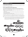
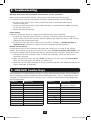
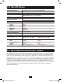
1
Owner’s Manual
8- and 16-Port NetCommander™
Cat5 Rackmount KVM Switches
Models: B072-008-1 and B072-016-1
Note: F
ollow these installation and operating procedures to ensure correct performance and to
prevent damage to this unit or to its connected devices.
1111 W. 35th Street, Chicago, IL 60609 USA • www.tripplite.com/support
Copyright © 2014 Tripp Lite. All rights reserved. All trademarks are the property of their respective owners.
14-03-231-933350.indd 1
3/27/2014 4:38:32 PM
Table of Contents
1. Features
2. System Components
3. Compatibility
4. Configuration
4.1 Front Panel
4.2 Back Panel
5. Installation
5.1 Rackmount Considerations
5.1.1 Ambient Operating Temperature
5.1.2 Airflow
5.1.3 Circuit Overloading
5.2 Rackmounting the NetCommander KVM
5.3 Pre-Installation Guidelines
5.4 Connecting the NetCommander KVM System
5.5 NetCommander Server Interface Unit (SIU)
5.5.1 PS/2 Server Interface Unit
5.5.2 USB Server Interface Unit
5.6 Connecting the Power Supply
5.7 Resetting the KVM Switch
5.8 Cascading NetCommander KVM Switches
3 6. Operation
3 6.1 Basic Operation
6.1.1 Pushbuttons
3
6.1.2 Keyboard Hotkeys
4 6.1.3 On-Screen Display (OSD)
4 6.2 On-Screen Display (OSD) 4 Functions
4 6.3 On-Screen Display (OSD)
F2 Settings
4 6.3.1
General
4
6.3.2 Ports
4 6.3.3 Time
4 6.3.4 Users
5 6.3.5 Security
8
8
8
8
8
8
9
9
11
11
12
12
7. Software
13
5 7.1 Firmware Upgrade 13
5 Computer Requirements
7.2 Firmware Upgrade 13
5 Software Requirements
7.3 Performing a Firmware 13
6 Upgrade
6 7.4 Physical Installation
13
6 7.5 Current Firmware Verification 13
7 7.6 Firmware Upgrade
16
7
8. Troubleshooting
17
9. USB/SUN Combo Keys
17
10. Specifications
18
11. FCC Radio/TV Interference Notice
18
12. Warranty & Registration
12.1 1-Year Limited Warranty
12.2 Warranty Registration
19
19
19
2
14-03-231-933350.indd 2
3/27/2014 4:38:32 PM
1. Features
• Access and control multiple computers from a single console
• Hot-swappable: disconnect and reconnect USB computers without rebooting
• Auto-scan: with variable time interval
• Compact design: 1U rack mountable
• Easy port selection using (1) On Screen Display (OSD), (2) front panel pushbuttons or
(3) keyboard Hotkeys key sequences
• Expandable: control up to 256 computers by adding additional KVM switches
• Simple cable management: use standard Cat5e/6 patch cord (maximum distance 100 ft) to
connect to each computer
• Multi-platform: supports PS/2 and USB computers/servers
• Comes with a USB to PS/2 converter for connecting a USB keyboard and mouse to the KVM's
PS/2 console ports
• Optional B051-000 IP Remote Access Unit to access the NetCommander over IP
2. System Components
• The NetCommander Cat5 KVM Switch consists of:
• B072-008-1 (8-Port) or B072-016-1 (16-Port) Cat5 KVM Switch
• USB to PS/2 converter
• Rackmount hardware
• 1 serial download cable (DB9 Female to RJ11 Male) for firmware upgrade
• C13 to 5-15P power cord
• Owner’s Manual CD
Accessories (available separately from Tripp Lite) include:
• Server interface units (SIU)—PS/2 (model B078-101-PS2) or USB (model B078-101-USB-1)
• Cat5e/6 cables (Tripp Lite model series: N001-, N002-, N201-, N202- or N105-)
3. Compatibility
• The NetCommander Cat5 KVM Switch is compatible with:
• PS/2 and USB computers/servers
• Video resolutions up to 1600 x 1200 @ 75Hz
• All major operating systems
3
14-03-231-933350.indd 3
3/27/2014 4:38:32 PM
4. Configuration
4.1 Front Panel
1
2
3
Figure 4.1 B072-016-1 NetCommander KVM front panel
1 Port Select Buttons: Press these buttons to toggle back and forth between ports. Pressing
both "Select" buttons at the same time also performs a system reset.
2 "Port Selected" LED: The "Port Selected" LED will illuminate above the port that is currently
selected.
3 "CPU On" LED: The "CPU On" LEDs will illuminate for all ports that have a server connected
(server must be powered on).
4.2 Back Panel
1
2
3
4
Figure 4.2 B072-016-1 NetCommander KVM rear panel
1 Power Socket: The power cord from the AC power source plugs in here.
2 Firmware Upgrade Port: Insert the included firmware upgrade cable here to download firmware
upgrade data.
3 CPU Port Section: Insert the Cat5/5e/6 cable from each PC or server.
4 KVM Console Ports: The keyboard, monitor and mouse plug in here.
5. Installation
5.1 Rackmount Considerations
5.1.1 Ambient Operating Temperature
The ambient operating temperature in the rack may be an issue and depends on the rack load and
ventilation. When installing the KVM switch in a closed or multi-unit rack assembly, make sure that
the temperature will not exceed the maximum rated ambient temperature.
5.1.2 Airflow
Ensure that the airflow through the rack is not compromised.
5.1.3 Circuit Overloading
When connecting the KVM switch to the supply circuit, consider the effect that overloading of
circuits might have on over-current protection and supply wiring.
Reliable grounding of all rack-mounted equipment must be maintained.
To protect against circuit overloading you should connect your Console KVM and attached
computers/servers to a Tripp Lite SmartPro® or SmartOnline® UPS System.
4
14-03-231-933350.indd 4
3/27/2014 4:38:34 PM
5. Installation (continued)
5.2 Rackmounting the NetCommander KVM
Use the L-shaped brackets and screws provided to mount the KVM in a server rack as
illustrated below.
Figure 5.2 Connecting the L-shaped bracket
Insert screws to
connect to rack
Insert screws to
connect to Switch
side panel
5.3 Pre-Installation Guidelines
• Switch off all computers
• Ensure that the cables are not close to any sources of electrical noise interference such as
fluorescent lights, HVAC systems or motors
• Ensure that the distance between any computer and the KVM switch does not exceed 100 ft.
• Shut down all PS/2 computers. If you plug the keyboard and mouse connectors into an active
PC, they may not work.
5.4 Connecting the NetCommander KVM System
Connect each computer to the KVM using a Server Interface Unit (SIU) and Cat5e/6 patch cable.
Figure 5.3 illustrates the connection options.
NetCommander B072-016-1 KVM Switch
Cat 5e/6 Cable
Cat 5e/6 Cable
SIU
SIU
SIU
Figure 5.4 NetCommander KVM system connections
5.5 NetCommander Server Interface Unit (SIU)
The Server Interface Unit receives power from the connected computer. In the case of the
NetCommander PS/2 Server Interface Unit (B078-101-PS2), power is drawn from the keyboard
port. In the case of the NetCommander USB Server Interface Unit (B078-101-USB-1), power is
drawn from the USB port. SIUs allow a computer/server to be located up to 100 ft. from the KVM
switch.
5
14-03-231-933350.indd 5
3/27/2014 4:38:35 PM
5. Installation (continued)
5.5.1 PS/2 Server Interface Unit
Connecting a NetCommander PS/2 Server Interface Unit (B078-101-PS2)
1.Shut down the computer being connected to the B078-101-PS2 (SIU)
2.Connect the B078-101-PS2 VGA connector to the computers VGA port
3.Connect the B078-101-PS2 PS/2 Keyboard connector to the computers PS/2 Keyboard port
4.Connect the B078-101-PS2 PS/2 Mouse connector to the computers PS/2 Mouse port
5.Connect one end of the Cat5e/6 patch cable to the RJ45 port on the B078-101-PS2*
6.Connect the other end of the Cat5e/6 patch cable to the desired RJ45 CPU port*
7.Repeat these steps for each additional PS/2 computer/server you are connecting to the KVM
* Cat5e/6 cable should be no longer than 100 ft.
To computer's
keyboard port
To computer's
mouse port
SIU
Up to 100 ft.
To computer's
VGA port
SIU = Server Interface Unit
Figure 5.5.1 NetCommander PS/2 Server Interface Unit
5.5.2 USB Server Interface Unit
Connecting a NetCommander USB Server Interface Unit (Model # B078-101-USB-1)
1.Connect the B078-101-USB-1 VGA connector to the computers VGA port
2.Connect the B078-101-USB-1 USB connector to the computers USB port
3.Connect one end of the Cat5e/6 patch cable to the RJ45 port on the B078-101-USB-1*
4.Connect the other end of the Cat5e/6 patch cable to the desired RJ45 CPU port*
5.Repeat these steps for each additional USB computer/server you are connecting to the KVM
* Cat5e/6 cable should be no longer than 100 ft.
To VGA port
To USB port
Up to 100 ft.
SIU = Server Interface Unit
Figure 5.4.2 NetCommander USB Server Interface Unit
5.6 Connecting the Power Supply
1.Plug in the KVM. Use only the power cord supplied with the unit.
2.Switch ON the computers.
6
14-03-231-933350.indd 6
3/27/2014 4:38:35 PM
5. Installation (continued)
5.7 Resetting the KVM Switch
To reset the KVM switch, press both "Select" buttons on the front panel simultaneously. The Server
Interface Units are unaffected by this reset.
5.8 Cascading NetCommander KVM Switches
To cascade two or more NetCommander KVM Switches, follow the instructions below. You can
connect up to 256 computers/servers in a complete 2-level installation. Note: The distance
between the first- and second-level KVMs, and between the second-level KVMs and connected
computers, cannot total more than 100 ft.
1.Connect a CPU port on the NetCommander KVM Switch to a B078-101-PS2 SIU using a
Cat5e/6 cable
2.Connect the B078-101-PS2's VGA connector to the VGA console port of the NetCommander
KVM Switch being cascaded
3.Connect the B078-101-PS2's keyboard and mouse connectors to the PS/2 console ports on
the NetCommander KVM Switch being cascaded
4.Repeat steps 1 through 3 for each additional NetCommander KVM Switch being cascaded
5.Connect any USB servers to the cascaded B072-Series KVM Switch using the B078-101-USB-1
6.Connect any PS/2 servers to the cascaded B072-Series KVM Switch using the B078-101-PS2
Note: In order to access the cascaded KVM's OSD, you must change the cascaded KVM's Hotkey
(see page 10 for details). Once the cascaded NetCommander KVM Switch is accessed, the
only way to access the cascaded KVM's ports is via the cascaded KVM's keyboard Hotkeys
or OSD. If the cascaded KVM's OSD security is set to On, the only way to access the
cascaded KVM's ports is by using your password to access the OSD.
SIU = Server Interface Unit
Figure 5.9 Cascading NetCommander KVM Switches
7
14-03-231-933350.indd 7
3/27/2014 4:38:37 PM
6. Operation
6.1 Basic Operation
The NetCommander KVM Switch provides three methods for accessing connected computers;
Pushbuttons, Keyboard Hotkeys and On-Screen Display (OSD).
6.1.1 Pushbuttons
Press the pushbuttons on the front panel of the KVM to toggle between the connected computers.
6.1.2 Keyboard Hotkeys
Keyboard hotkeys allow you to toggle between ports using the keyboard. To access the first
accessible port after the currently selected port, press and release the [Shift] key, and then press
and release the plus [+] key. To access the first accessible port prior to the currently selected
port, press and release the [Shift] key, and then press and release the minus [-] key.
6.1.3 On-Screen Display (OSD)
To access the OSD, press and release the [Shift] key twice. When activated, the OSD main page
opens with the port list displayed. Ports that have a powered-on computer connected to them will
be displayed using Blue text. Ports that do not have a computer connected to them, or that have
a powered-off computer connected, will be displayed using Gray text. By default, ports that are
displayed in Gray will not be accessible to the user. If you want to be able to access these ports,
you must turn off the Auto Skip setting in the General section of the OSD. (See the General section
under On-Screen Display OSD F2 Settings for details).
Selecting a Port
To select a port in the OSD main page, use the [ ] and [ ] keys to highlight the desired port, and
then press the [Enter] key.
6.2 On-Screen Display (OSD) Functions
The OSD main menu displays the various functions that can be performed using keyboard keys.
These functions are described in the following sections.
F1 – HELP
Press the [F1] key to access the HELP screen. The HELP screen displays the functions that are
available, and what keys are used to activate them.
F2 – SETTINGS
Press the [F2] key to pull up the OSD SETTINGS screen. From this screen you can configure the
KVM and add/edit user accounts. The F2 – SETTINGS section is described in detail in the On-Screen
Display (OSD) F2 Settings section.
F4 – SCAN
Press the [F4] key to initiate an Auto Scan. When initiated, an Auto Scan automatically switches
between accessible ports at a pre-determined time interval. By default, each port is scanned for
30 seconds. The scan interval can be edited in the Time settings screen. (See Time section under
On-Screen Display OSD F2 Settings for details) During an Auto Scan, press the [F4] key to stop the
scan at the currently selected port.
8
14-03-231-933350.indd 8
3/27/2014 4:38:37 PM
6. Operation (continued)
F5 – TUNING
As computers are located further away from the KVM switch, the video can become distorted. In the
event you are experiencing poor video quality, the TUNING function can be used to correct it. Press
the [F5] key to display the currently selected port, with the TUNING bar displayed. Use the [←] and
[→] keys to make the necessary adjustments. When you are finished, press the [Esc] key to go
back to the OSD. Note: Tuning is performed on a port-by-port basis. You will need to adjust each
port individually.
F6 – MOVE LABEL
By default, the label that displays each ports Port Name appears in the top-center of the screen, but
it can be moved anywhere on the screen that you want. Press the [F6] key to display the currently
selected port and its label. Use the [↑], [↓], [←] and [→] keys to move the label to the desired
location, and then press the [Esc] key to go back to the OSD. Note: Setting the label location is
performed on one port at a time. You can move the label to different locations on different ports.
F10 – NEW MONITOR – DDC2
In the event that one of the connected computers does not display an image on the console
monitor (e.g. You get the error message ‘Unable to Display Video Mode’), you may need to update
the DDC information being used by the console monitor. To do this, follow the steps below.
1.Remove the SIU VGA connectors from the connected computers, while leaving the PS/2 and /or
USB connectors plugged in.
2.Open the OSD main menu and press the [F10] key. The OSD will flash the message “Please
Wait.” When that message disappears, the update is complete.
3.Reconnect the SIU VGA connectors to the connected computers. You should now be able to
display video from all of the remote computers.
6.3 On-Screen Display (OSD) F2 SETTINGS
Press the [F2] key to pull up the OSD SETTINGS screen. From this screen you can configure the
KVM and add/edit user accounts. The pages that follow describe the sections of the F2 SETTINGS
page, and the settings included in them. Note: When local security is turned on, the KVM
administrator is the only one that can access the F2 SETTINGS page.
6.3.1 General
Highlight the General option and press the [Enter] key to open the GENERAL SETTINGS page. This
page allows you to turn the KVMs local security settings on/off, as well as to configure some of the
basic KVM settings. The table below describes the settings found in this page.
Setting
Description
Security
By default, the Security setting is turned off. To activate the Security setting,
highlight it and press the [Spacebar]. Upon pressing the [Spacebar], you
will be prompted to enter the administrator password in order to change the
Security setting. The default administrator password is ADMIN. For security
purposes, it is recommended that you update the administrator password
to something unique. (See the Security Settings section for details) Note:
When security is activated, the keyboard hotkey commands are disabled,
leaving the OSD as the only way for you to locally access the connected
computers. Upon pressing the [Shift] [Shift] invocation command, you will
be prompted to enter your password before the OSD can be accessed. The
security settings in this OSD are exclusive to the local console, and do not
affect the remote access security settings.
9
14-03-231-933350.indd 9
3/27/2014 4:38:37 PM
6. Operation (continued)
6.3 On-Screen Display (OSD) F2 SETTINGS
(continued)
Hotkey
By default, the hotkey used in keyboard hotkey commands and to open the
OSD is the [Shift] key, but this can be changed to any of the four options
below. To toggle between commands, highlight the Hotkey option and press
the [Spacebar] key.
(SH-SH)
• Press and release the [Shift] key twice to open the OSD.
• Press and release the [Shift] key, and then press and release the plus
[+] key to switch to the next accessible port.
• Press and release the [Shift] key, and then press and release the minus [-]
key to switch to the previous accessible port.
(CL-CL)
• Press and release the Left [Ctrl] key twice to open the OSD; or, press and
release the Right [Ctrl] key, and then press and release the Left [Ctrl] key.
• Press and release either [Ctrl] key, and then press and release the plus
[+] key to switch to the next accessible port.
• Press and release either [Ctrl] key, and then press and release the minus
[-] key to switch to the previous accessible port.
(CLF11)
• Press and release either [Ctrl] key, and then press and release the [F11]
key to open the OSD.
• Press and release either [Ctrl] key, and then press and release the plus
[+] key to switch to the next accessible port.
• Press and release either [Ctrl] key, and then press and release the minus
[-] key to switch to the previous accessible port.
(PRSCR)
• Press and release the [Print Screen] key once to open the OSD.
• When you choose [Print Screen] as your hotkey, the keyboard hotkey
commands are disabled, leaving the OSD as the only way to access the
connected computers.
Autoskip
By default, the Autoskip setting is enabled, which prevents users from accessing ports that either don’t have a computer connected to them, or that
have a powered-off computer connected to them. To toggle this setting on/
off, highlight it and press the [Spacebar] key.
Serial Port
By default, the Serial Port setting is enabled, which allows a local firmware
upgrade to be performed. To toggle this setting on/off, highlight it and press
the [Spacebar] key. Note: This setting affects the firmware upgrade port
only, and has nothing to do with the Serial port on the back of the unit.
Keyboard Language By default, the Keyboard Language setting is set to US English, but it can
be changed to French (FR) or German (DE). To toggle between these three
language settings, highlight the Keyboard Language setting and press the
[Spacebar] key.
Switch Name
By default, the switch name is NETCOMMANDER 16IP, but this can be
changed. Simply move the OSD cursor to the Switch Name and type in the
desired name. Delete any characters that you don’t want. The Switch Name
can be up to 18 characters in length, with spaces counting as characters.
F7 – Defaults
You can restore the default settings of the local OSD by pressing the [F7]
key. When pressed, you will be prompted to confirm that you wish to continue. If yes, press the [Y] key to restore the default values. Note: All of the
local OSD settings, including Security and User Settings, will be restored.
10
14-03-231-933350.indd 10
3/27/2014 4:38:37 PM
6. Operation (continued)
6.3 On-Screen Display (OSD) F2 SETTINGS
(continued)
6.3.2 Ports
Highlight the Ports option and press the [Enter] key to open the Port Settings page. This page allows
you to edit port names, set the remote computer keyboard type, and set the hotkey for ports that
have second level KVM switches connected to them. The table below describes each of these
settings.
Column
Description
NAME
The first column displays the name associated to each port. You can change this
by moving the cursor to the desired port name and simply typing over the existing
name with the desired name. Port names can be up to 15 characters in length, with
spaces counting as characters.
KB
The second column displays the keyboard type associated with each port. By default,
each port is set to PS, which works with Intel-based computers and UNIX servers
connected using a B078-101-USB-1. To toggle this setting between the options listed
below, move the cursor to the desired port, press the [Tab] key to move to the KB
column, and then press the [Spacebar] key.
• PS – Intel-based computers and UNIX servers connected using a B078-101-USB-1
• U1 – HP UX
• U2 – Alpha UNIX, SGI or Open VMS
• U3 – IBM AIX
HKEY
By default, the HKEY setting for each port is NO, which means that a computer
is connected to it. When a second level KVM is connected to a port, you need to
update this setting to display its hotkey. To toggle this setting between the various
hotkeys, move the cursor to the desired port, press the [Tab] key to move to the
HKEY column, and then press the [Spacebar] key.
6.3.3 Time
Highlight the Time option and press the [Enter] key to open the Time Settings page. This page lists
all of the KVM ports on the left, and 3 time columns on the right, which are described below.
SCN – Sets the amount of time spent on the selected port during an Auto Scan. The default scan
interval is 30 seconds. A setting of 000 causes the corresponding port to be skipped during an Auto
Scan.
LBL – Sets the amount of time that the port’s label is displayed on screen. The default label display
time is 30 seconds. A setting of 999 causes the label to be displayed continuously. A setting of 000
causes the label not to appear at all.
T/O – When Security is enabled, you set the KVM to logout after a specified amount of time. When
this time is reached, entering the OSD invocation command brings up a prompt asking you to
enter a password, which is required to regain access to the KVM. The default timeout value is 30
seconds. A setting of 999 disables the timeout function. Note: A setting of 000 causes the KVM to
logout immediately, not allowing the user enough time to hit the OSD invocation command to pull
up the password prompt. It is recommended that you always keep the timeout setting at 5 seconds
or higher. If you set the timeout setting at 000 and get locked out of the KVM, turn the unit off and
then back on. When turned back on, you will be able to use the OSD invocation command to pull
up the password prompt and regain access to the OSD.
To set the time periods mentioned above, follow the steps below.
1. Move the cursor to the desired port row and press the [Tab] key to jump to the desired column.
2. When the cursor is moved to the desired column, simply type in the time interval.
11
14-03-231-933350.indd 11
3/27/2014 4:38:38 PM
6. Operation (continued)
6.3 On-Screen Display (OSD) F2 SETTINGS
(continued)
6.3.4 Users
The Users option can only be accessed when Security is enabled in the General Settings page.
(See General under On-Screen Display OSD F2 Settings section for details.) Highlight the Users
option and press the [Enter] key to open the User Settings page. In the column on the left side
of the screen, all of the ports on the KVM are listed. On the right side of the screen, there are
6 columns; one for each user account. For example, column 1 represents the first user account
that is displayed in the Security Settings page. (See the Security Settings section for details.) The
letters in each column represent the access rights that the corresponding user account has for
the corresponding port. There are three types of access a user can be given to a port, which are
described below.
• Y – A Y signifies that the corresponding user account has full access rights to the corresponding
port.
• V – A V signifies that the corresponding user account has view-only access rights to the
corresponding port, meaning that they can view the remote video, but are not allowed to control
the connected computer with the keyboard and mouse.
• N – A N signifies that the corresponding user account is not allowed to access the corresponding
port.
To change the User settings, the administrator must follow the steps below.
1.In the User Settings page, use the [↓] and [↑] keys to move the cursor to the desired port row.
2.Use the [←] and [→] keys to move the cursor to the desired account column.
3.Press the [Spacebar] key to toggle between the different access types.
6.3.5 Security
The Security option can only be accessed when Security is enabled in the General Settings page.
(See General under On-Screen Display OSD F2 Settings section for details) Highlight the Security
option and press the [Enter] key to open the Security Settings page. The Security Settings page
displays all of the available accounts for the KVM; 1 administrator, 1 supervisor and 6 users. The
first column lists the account Name, the second column lists the account Password, and the third
column lists the account Type. The three available account types are described below.
• Administrator – There is one administrator account available. The administrator has full access
to all ports and settings on the KVM. The administrator is the only account that can access the
F2 SETTINGS menu in the OSD.
• Supervisor – There is one supervisor account available. The supervisor has full access to all
ports on the installation, but is not allowed to access the F2 SETTINGS menu in the OSD. The
supervisor is allowed to access the F1 HELP, F4 SCAN, F5 TUNING, F6 MOVE LABEL and F10
NEW MONITOR DDC functions in the OSD.
• User – There are six user accounts available. Users’ port access rights are limited to those
assigned to them by the administrator. Users are not allowed to access the F2 SETTINGS menu
in the OSD, but can access the F1 HELP, F4 SCAN, F5 TUNING, F6 MOVE LABEL and F10 NEW
MONITOR DDC functions.
To change the Security settings, the administrator must follow the steps below.
1.In the Security Settings page, use the [↓] and [↑] keys to move the cursor to the desired account
row.
2.To edit the account Name, simply type the desired name over the current one, and delete any
unnecessary characters. Note: The account Name is for organizational purposes only. The
Password is the only thing an account needs to enter to gain access to the KVM.
3.To edit the account Password, press the [Tab] key to move the cursor to the Password column,
and then enter in the desired password over the current one. Delete any unnecessary characters.
12
14-03-231-933350.indd 12
3/27/2014 4:38:38 PM
7. Firmware Upgrade
7.1 Firmware Upgrade Computer Requirements
• Windows 2000 or higher operating system
• Pentium 166 or higher with 16MB RAM and 10MB free hard drive space
• Available DB9 serial port
7.2 Firmware Upgrade Software Requirements
• Firmware Upgrade Utility—This Windows-based application reads the current firmware and
installs the new firmware of the KVM and Server Interface Units (SIUs). Note: The firmware
upgrade utility is compatible with Windows 32-bit operating systems only.
• Firmware Upgrade File—This file contains the actual firmware for the KVM and SIUs.
7.3 Performing a Firmware Upgrade
There are several steps to performing a firmware upgrade on your KVM switch and SIUs: Physical
Installation, Current Firmware Verification and Firmware Upgrade. Each of these steps is described
in the sections that follow. Note: Each KVM switch in a cascaded installation must be upgraded
separately.
7.4 Physical Installation
The first step in performing a firmware upgrade is to physically connect the KVM switch to a
computer that is not a part of the KVM installation (i.e. not connected via Cat5e/6 cable and an
SIU). To do this, follow the steps below.
1.Make sure that the Serial Port setting in the General Settings page of the OSD is enabled. (See
the General section under On-Screen Display OSD F2 Settings for details.) If this setting is
disabled, you will not be able to perform a firmware upgrade.
2.Connect the RJ11 Firmware Upgrade port on the back of the KVM to a DB9 serial port on the
upgrade computer using the included RJ11 to DB9 firmware upgrade cable.
7.5 Current Firmware Verification
After the physical connection is made, you must install the Firmware Upgrade Utility on the upgrade
computer (the computer you just connected to the KVM) and then check the current firmware
version on your KVM to see if it needs to be updated. To do this, follow the steps below.
1.On the upgrade computer, go to
www.tripplite.com/support and download
the latest firmware for the B072-008-1 or
B072-016-1. The Firmware Upgrade Utility
and KVM/SIU Firmware Upgrade File will be
downloaded together.
2.Run the Firmware Upgrade Utility to install
it on the upgrade computer. Follow the
installation prompts to install the utility.
Figure 7.1: Firmware Upgrade Utility Setup
13
14-03-231-933350.indd 13
3/27/2014 4:38:38 PM
7. Firmware Upgrade (continued)
7.5 Current Firmware Verification
(continued)
3.When installation is complete, clicking the Finish button will automatically open the Firmware
Upgrade Utility with the main screen displayed.
Figure 7-2: Firmware Upgrade Utility Main Screen
4.There are three types of firmware to be verified; OSD, Manager and SIU. Start by checking the
NetCommander CAT5 KVM Switch OSD box at the top of the utility, and then click the F/W Version
button at the bottom of the utility to display the firmware version number. Check this against the
firmware you downloaded from the Tripp Lite website to determine if an upgrade is needed.
Figure 7-3: OSD Verification
14
14-03-231-933350.indd 14
3/27/2014 4:38:38 PM
7. Firmware Upgrade (continued)
7.5 Current Firmware Verification
(continued)
5.Uncheck the NetCommander CAT5 KVM Switch OSD box, and check the box next to
NetCommander CAT5 KVM Switch Manager. Click the F/W Version button at the bottom of the
utility to display the firmware version number. Check this against the firmware you obtained from
the Tripp Lite website to determine if an upgrade is needed.
Figure 7.4: Manager Verification
6.Uncheck the NetCommander CAT5 KVM Switch Manager box, and check the box in the middle
of the utility next to each SIU for which you want to verify the firmware. Click the F/W Version
button at the bottom of the utility to display the firmware version number. Check this against the
firmware you obtained from the Tripp Lite website to determine if an upgrade is needed.
Figure 7.5: SIU Verification
15
14-03-231-933350.indd 15
3/27/2014 4:38:38 PM
7. Firmware Upgrade (continued)
7.6 Firmware Upgrade
Once you have determined that your KVM and/or SIU(s) need to be upgraded, follow the steps
below to install the new firmware.
1.In the Firmware Upgrade Utility main screen, open the Options drop-down menu at the top of the
screen and select the Com Port option. Select the com port of the upgrade computer that the
Firmware Upgrade Cable is connected to and click OK.
2.Open the File drop-down menu at the top of the screen and select the Open option. Navigate to
and select the firmware upgrade file you downloaded from the Tripp Lite website.
3.To upgrade the OSD firmware, check the NetCommander CAT5 KVM Switch OSD box, and
then click the Start button to begin the upgrade process. A prompt will appear to warn you that
the KVM screen will be dark during the upgrade process. Click OK to proceed. Towards the end
of the upgrade, a prompt will appear asking if you want to set the OSD to its default settings. If
yes, click the Yes button. If no, click the No button. The upgrade will finish, and the new firmware
version number will be displayed.
4.To upgrade the Manage firmware, check the NetCommander CAT5 KVM Switch Manager box,
and then click the Start button to begin the upgrade process. A prompt will appear to warn you
that the KVM screen will be dark during the upgrade process. Click OK to proceed. Towards the
end of the upgrade, a prompt will appear asking if you want to set the OSD to its default settings.
If yes, click the Yes button. If no, click the No button. The upgrade will finish, and the new
firmware version number will be displayed.
5.To upgrade the SIU firmware, check the box(es) in the middle of the utility next to the SIU(s)
you wish to upgrade, and then click the Start button to begin the upgrade process. A prompt will
appear to warn you that the KVM screen will be dark during the upgrade process. Click OK to
proceed. The upgrade will finish, and the new firmware version number will be displayed.
16
14-03-231-933350.indd 16
3/27/2014 4:38:38 PM
8. Troubleshooting
Warning: Disconnect device from AC mains before service operation!
When using Firmware Update software, you may get a Communication Error message.
If a Communication Error message appears during the update procedure, do the following:
1.Ensure that the RS232 serial cable's RS232 connector is connected to the switch's
communication port
2.Ensure that the RS232 serial cable's DB9F connector is connected to the DB9M serial port
on the CPU's rear panel
3.Restart the download process
Power Failure
If electrical power fails during an update to the KVM firmware, do the following:
1.If power fails while the switch firmware is updating, a communication error message will
appear. Simply resume the firmware update by opening the folder that contains the firmware
update file and continue from there
2.If power fails while the Server Interface Unit firmware is updating, a "Not Responding" or
"Upgrade Error" message will appear. Restart the upgrade from the beginning
Monitor Screen Failure
In the event that one of the connected computers does not display an image on the console
monitor (your monitor may display an error message saying "Unable to Display Video Mode"), you
may need to update the DDC information from the console monitor. To do this, follow these steps:
1.Remove the SIU VGA connectors from all connected computers. Leave the USB or PS/2
connectors attached
2.Open the OSD main menu and press [F10]. The OSD will flash the message "Please Wait."
When that message stops, the update has taken place
3.Reconnect the SIU VGA connectors of all the attached computers. You should now be able to
display video from all computers
9. USB/SUN Combo Keys
The connected PS/2 keyboard does not have a special SUN keypad to perform special functions in
the SUN Operating System environment. When a B078-101-USB-1 (SIU) is connected to a SUN
computer, the SIU emulates these SUN keys using a set of key combinations called Combo Keys.
See the table below:
SUN Key
Stop
Props
Front
Open
Find
Again
Undo
Copy
Paste
Cut
Help
Combo Key
Left Ctrl + Alt
Left Ctrl + Alt
Left Ctrl + Alt
Left Ctrl + Alt
Left Ctrl + Alt
Left Ctrl + Alt
Left Ctrl + Alt
Left Ctrl + Alt
Left Ctrl + Alt
Left Ctrl + Alt
Left Ctrl + Alt
+
+
+
+
+
+
+
+
+
+
+
SUN Key
Compose
F1
F3
F5
F7
F9
F2
F4
F6
F8
F10
F11
Crescent
Volume Up
Volume Down
Mute
Sun Left key
Sun Right key
Alt-Graph
Stop A
Combo Key
Application key or Left
Ctrl + Alt + Keypad *
Scroll Lock
Left Ctrl + Alt + Keypad Left Ctrl + Alt + Keypad +
Left Ctrl + Alt + F12
Left Windows key
Right Windows key
Right Alt or Alt Gr
Left Ctrl + Alt + 1
17
14-03-231-933350.indd 17
3/27/2014 4:38:39 PM
10. Specifications
Operating Systems
Optional External Mouse
Resolution
NetCommander KVM
Switch
Dimensions - 8/16 port
Weight - 8/16 port
Power Supply
Connections
System
Serial
Monitor
Keyboard
Mouse
Operating / Recommended
Ambient Temperature
Storage Temperature
Humidity
NetCommander Server
Interface Units
Connections
VGA
Keyboard/Mouse
System
Power
Compatible with all major operating systems
PS/2, Wheel mouse, Intellimouse, 5-button mouse
1600x1200@75Hz
Models B072-016-1 or B072-008-1
17” x 5” x 1.7” (unit)
Product - 3.7 lbs.
Shipping - 5.5 lbs.
Internal switching 100-240 VAC 50 / 60 Hz
RJ45
RJ11
HD15
MinDin6
MiniDin6
32°F to 104°F
-40°F to 158°F
80% non-condensing relative humidity
Model B078-101-PS2
Model B078-101-USB-1
HD15
MiniDin6
RJ45
From Keyboard port
HD15
USB
RJ45
From USB port
11. FCC Radio/TV Interference Notice
This equipment has been tested and found to comply with the limits for a Class A digital device,
pursuant to Part 15 of the FCC Rules. These limits are designed to provide reasonable protection
against harmful interference when the equipment is operated in a commercial environment. This
equipment generates, uses and can radiate radio frequency energy and, if not installed and used in
accordance with the instruction manual, may cause harmful interference to radio communications.
Operation of this equipment in a residential area is likely to cause harmful interference in which
case the user will be required to correct the interference at his own expense. The user must use
shielded cables and connectors with this product. Any changes or modifications to this product not
expressly approved by the party responsible for compliance could void the user's authority to
operate the equipment.
18
14-03-231-933350.indd 18
3/27/2014 4:38:39 PM
12. Warranty & Registration
12.1 1-Year Limited Warranty
TRIPP LITE warrants its products to be free from defects in materials and workmanship for a period of one (1) year from the date of
initial purchase. TRIPP LITE's obligation under this warranty is limited to repairing or replacing (at its sole option) any such defective
products. To obtain service under this warranty, you must obtain a Returned Material Authorization (RMA) number from TRIPP LITE
or an authorized TRIPP LITE service center. Products must be returned to TRIPP LITE or an authorized TRIPP LITE service center with
transportation charges prepaid and must be accompanied by a brief description of the problem encountered and proof of date and
place of purchase. This warranty does not apply to equipment, which has been damaged by accident, negligence or misapplication
or has been altered or modified in any way.
EXCEPT AS PROVIDED HEREIN, TRIPP LITE MAKES NO WARRANTIES, EXPRESS OR IMPLIED,
INCLUDING WARRANTIES OF MERCHANTABILITY AND FITNESS FOR A PARTICULAR PURPOSE. Some states do not permit limitation
or exclusion of implied warranties; therefore, the aforesaid limitation(s) or exclusion(s) may not apply to the purchaser.
EXCEPT AS PROVIDED ABOVE, IN NO EVENT WILL TRIPP LITE BE LIABLE FOR DIRECT, INDIRECT,
SPECIAL, INCIDENTAL OR CONSEQUENTIAL DAMAGES ARISING OUT OF THE USE OF THIS PRODUCT, EVEN IF ADVISED OF THE
POSSIBILITY OF SUCH DAMAGE. Specifically, TRIPP LITE is not liable for any costs, such as lost profits or revenue, loss of
equipment, loss of use of equipment, loss of software, loss of data, costs of substitutes, claims by third parties, or otherwise.
12.2 Warranty Registration
Visit www.tripplite.com/warranty today to register the warranty for your new Tripp Lite product. You'll be automatically entered into a
drawing for a chance to win a FREE Tripp Lite product!*
* No purchase necessary. Void where prohibited. Some restrictions apply. See website for details.
WEEE Compliance Information for Tripp Lite Customers and Recyclers (European Union)
Under the Waste Electrical and Electronic Equipment (WEEE) Directive and implementing regulations, when
customers buy new electrical and electronic equipment from Tripp Lite they are entitled to:
•Send old equipment for recycling on a one-for-one, like-for-like basis (this varies depending on the country)
•Send the new equipment back for recycling when this ultimately becomes waste
TRIPP LITE follows a policy of continuous improvement. Specifications are subject to change without notice.
19
14-03-231-933350.indd 19
3/27/2014 4:38:39 PM
1111 W. 35th Street, Chicago, IL 60609 USA • www.tripplite.com/support
20
14-03-231-933350.indd 20
14-03-231 • 93-3350_revA
3/27/2014 4:38:39 PM