1
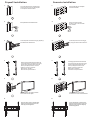
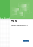
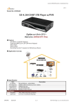
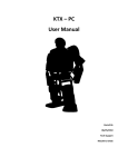
INSTRUCTION MANUAL SPECIFICATIONS Display Size: up to 46” Maximum Load: 35 kg Mounting Pattern: 400 mm x 400mm (max) Profile:11.1cm-39cm Tilt:15 down Swivel: up to 180 BOX CONTENTS Wall bracket (x1) Mount arms (x 2) Instruction Manual (x1) Hardware Kit (x1) WARNINGS 1.The wall or mounting surface must be capable of supporting the combined weight of the mount and the display; if not, the structure must be reinforced. 2.Locate pipes, wires, or any other hazards in the wall where you wish to install the mount before drilling. 3.Safety gear and proper tools must be used. Failure to do so can result in injury or damage. 4.Two people are recommended for installation. Do not attempt to lift a heavy display without assistance. 5.Follow all instructions and recommendations regarding adequate ventilation and suitable locations for mounting your display. Consult the owner's manual for your particular display for more information. CAUTION: This wall mount is intended for use only with the maximum weight of 35 kg . Use with heavier than the maximum weights indicated may result in instability causing possible injury. TOOLS REQUIRED Screwdriver Electric or Portable Drill Drill Bit and Stud Finder for Drywall Installation Masonry Bit for Concrete Installation Hammer Tape Measure HARDWARE KIT (A)M6 x 50 Lag Bolt (x3) (B) Lag Bolt Washer (x3) (C)Concrete Anchor (x3) (D)M4 x 20Screw (x4) (E)M6x 20 Screw (x4) (J)M6 Washer (x4) (K)Spacer (x4) Drywall Installation 1. Concrete Installation 1. Use a stud finder to locate a stud where you wish to install your mount. Use the wall plate as a template to mark three holes. 2. 3. Drill a pilot hole at each marked location. Fix the wall plate onto the wall using (A), (B) and (C) provided from the hardware kit. 4. 2. 3. Use the wall plate as a template to mark three holes. Drill a hole at each marked location. Insert a concrete anchor into each hole. Fix the wall plate onto the wall using (A), (B) and (C)provided from the hardware kit. 4. Choose (D)/(F) provided from the hardware kit to fix the mount arms to the back of your display. Spacers and (E)/(G)/(H) should be used if the back of your display is curved or recessed. display is curved or recessed. bolts require washers. bolts do not require washers. Choose (D)/(F) provided from the hardware kit to fix the mount arms to the back of your display. Spacers and (E)/(G)/(H) should be used if the back of your display is curved or recessed. display is curved or recessed. bolts require washers. bolts do not require washers. 5. 5. Carefully mount your display with the mount arms onto the mount. Carefully mount your display with the mount arms onto the plate. 6. 6. Insert the safety screws to the bottom of the mount arms and tighten to prevent the display from being lifted. Insert the safety screws to the bottom of the mount arms and tighten to prevent the display from being lifted.