1
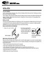
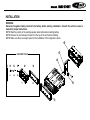
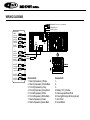
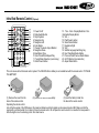
INSTALLATION
Tools for Installation
Use the 2 removal wrenches of the old unit to take out the old unit and place with this brand new car radio. The following tools and supplies may also be needed for the installation:
Tools for Installation: Philips Screw-drivers /Machine Screws /Wire Stripper /Wire Cutter /Hammer /Pencil /Electrical Tape /Electric Drill
Supplies for Installation: Machine Screws /Crimp Connectors /14 Gauge Wire for Power Connections /14-16 Gauge Speaker Wires
The above are not supplied.
Before you install
Automotive audio equipment installations can be challenging even to the most experienced of installation technicians. We strongly recommend that this unit should be professionally installed by a VAT registered installer (this is a requirement to validate the warranty).
IMPORTANT: Remove the two transport screws from the top fo the unit before installing.
Remove the Old Unit from the Dashboard
1. Remove the outer trim frame.
DIN Front Mount
Mark Polarity of the Speaker Wires
2. Insert the keys supplied with the
old unit into both sides of the unit
as shown in figure below until
they click. Pull to remove the old
unit from the dashboard.
DO NOT DISCONNECT WIRES
AT THIS TIME!
Marking the polarity of the speaker wirers will make it easier to connect the existing speakers to your car radio. Consult wiring diagram
of existing head unit before disconnecting any wires. If you are not positive of the polarity of the existing wires from the speakers to the
head unit, install new wires.
1. While the old unit is playing, disconnect the wires from one speaker.
2. Take a length of masking tape and fold it around the wire so it forms a flag.
3. On the masking tape mark the polarity of the speaker wires (+&-), as well as left or right, and front or rear.
4. Double check that you marked the first speaker correctly by checking that the speaker wires are the same at the head unit.
5. Repeat this procedure for all of the speakers.
6. Mark the power, ground, and any other wires also.
INSTALLATION
WARNING!
Disconnect negative battery terminal from battery before starting installation. Consult the vehicle’s owner’s
manual for proper instructions.
NOTE: Mark the polarity of the existing speaker wires before disconnecting battery.
NOTE: Remove the two transport screws from the top of the unit before installing.
NOTE: Make sure there is enough space for the installation of this single-din in-dash.
SUPPLIED TOOLS
WIRING DIAGRAM
Microphone IN (3.5mm jack) > only for RMD574BT
Parking brake (green)
Reverse (purple/white)
Steeringwheel
control
(3.5mm jack)
Camera IN
(yellow RCA)
Video OUT
(yellow RCA)
Sub OUT
(green RCA)
Video IN
(yellow RCA)
Audio IN
Left (white RCA)
Audio IN
Radio
Antenna
Right (red RCA)
Audio OUT
F-left (white RCA)
Audio OUT
F-right (red RCA)
Audio OUT
R-left (white RCA)
Audio OUT
R-right (red RCA)
Connector A
1. Rear right speaker(+)/Purple
2. Rear right speaker(-)/Purple-Black
3. Front right speaker(+)/Grey
4. Front right speaker(-)/Grey-Black
5. Front left speaker(+)/White
6. Front left speaker(-)/White-Black
7. Rear left speaker(+)/Green
8. Rear left speaker(-)/Green-Black
Connector B
1. 2. 3. 4. Battery 12V (+)/Yellow
5. Antenna power/Blue-White
6. Panel light/Orange-White (optional)
7. ACC+/Red
8. Ground/Black
WIRING DIAGRAM
General Wiring Notes:
Make sure You have a good chassis ground. Good ground connection will eliminate most electrical noise problems. A good chassis
ground requires a tight connection to the .vehicle’s metal chassis. The area around the ground connection should be clean, bare metal
without rust, paint, plastic, dust, or dirt for a good ground connection.
Black Ground
Connect to vehicle body/chassis. Make sure you have a good chassis ground. This will eliminate most electrical noise form the motor
and alternator. A good chassis ground requires a tight connection to ground. The area should be free from rust, paint or any form of dirt.
Red Ignition
Connect to car ignition switch for main power supply of the unit.
Yellow Memory Backup
Connect to electrical terminal always supplied with power regardless of ignition switch position.
Blue-White Remote
Connect to Auto-antenna or power amp control wire/remote connection. Maximum current 300mA 12VDC. (Low Current)
Green (Hand Brake - Ground)
Connect this wire to the hand brake wire of your car so that the display will be on only when the car is fully stopped.
Purple-White (Rear Gear - VCC)
Connect this wire to the rear gear wire of your car so that the backup camera function can be activated when you car is in reverse gear.
Orange-White (Panel Light)
Connect the this wire to the car light switch so that the front panel illumination will be on when the car light switch is turned on.
Various outputs (Refer to the wiring diagram)
Refer to the wiring diagram for the connection details.
Speaker Wiring Notes:
Follow the above wiring diagram to install the head unit with new or existing speakers.
1. This unit is designed for use with four (4) speakers with impedance between 4 Ohms to 8 Ohms.
2. An Impedance load of less than 4 Ohms could damage the unit.
3. Never bridge or combine the speaker wire outputs. When not using four speakers, use electrical tape to tape the ends of the unused
speaker outputs to prevent a short circuit.
4. Never ground the negative speaker terminals to chassis ground.
Basic Operation
1. Turning the unit on/off
Press the POWER button to turn the unit on. Press and hold the POWER button again to turn off.
2. Sliding out the monitor
Press the TILT button so that the monitor will slide out automatically and the main GUI display will show up. Press the TILT button again
so that the screen will go back in the chassis.
3. Angle of the screen
Press the UP/DOWN arrow buttons so that the screen will tilt up or down. There are 4 steps for tilting (ANGLE 0-4).
4. Screen blackout / Video output
Press the POWER button once to turn the TFT off (when screen picture is not required). During video playback, the video signal will
be sent to connected monitor (if connected) so that the screen will show on these connected monitors. The TFT will be showing in low
resolution to indicate video output is in use.
5. Day Light Saving
Tap the Day button on the OSD to increase brightness. Tap again to reduce brightness during night time. Tap again for black out the
screen.
6. Mode Selection
Press the MODE Button to cycle the Play Modes between RADIO, USB, SD and AUX in.
7. Sound Control
A. Volume
Use the VOL +/- Button to adjust the volume level. Turn the button clockwise to increase the volume, and vice versa. The larger the number of volume, the higher the volume level. You can also adjust the volume by sliding the volume icon on top of the screen.
B. Bass
Press the SEL Button until the display shows “BAS”. Use the VOL +/- Button to adjust. When EQ is ON, bass control is not available.
C. Treble
Press SEL Button until the display shows “TRE”. Use the VOL +/- Button to adjust. When EQ is ON, treble control is not available.
D. Balance
Press SEL Button until the display shows “BAL”, then use the VOL +/- Button to adjust the balance between the left & right speakers.
E. Fader
Basic Operation
Press SEL Button until the display shows “FAD”, then use the VOL +/- Button to adjust the balance between the front & rear speakers.
F. Other Audio Settings
You can adjust other audio settings like preset equalizer, loudness or subwoofer ON/OFF by tapping the “EQ” icon on the main menu, or
on the control menu of other audio/video play modes.
8. SETUP
Enter the setup menu in the home screen by tapping the “SETTING” icon on the main menu. Tap the items you would like to set. You can
adjust audio, date and time, language, cabibration, etc.
Radio Operation
1. Choose Radio Band
Touch the BAND button onscreen to choose among the five radio bands - three FM Bands (FM1, FM2, and FM3) and two AM Bands
(AM1, and AM2). Each of the five bands can store up to six preset stations, for a total of 30 preset memory stations.
2. Radio Seek Function
In Radio Mode, touch and hold >> or << Button to adjust the radio frequency automatically. Press the button once to adjust the radio
frequency manually.
3. Save Your Preset Stations
There are six numbered preset buttons on the the screen (P1-P6) which can store and recall stations for each band. While listening to a
radio station you would like to save as a preset, touch and hold any key from P1-P6 until you hear a beep. The station will be saved in
the designated number.
4. Mono/Stereo Reception Control
In FM radio mode, touch the ST button to select stereo or mono reception.
5. Local/Distance Reception Control
In radio mode, touch the LOC button to select local or distance reception.
6. RDS Control (Optional)
AF, TA, PTY are the RDS functions. They are applicable to certain countries only. For countries when RDS is not available. The touch
sensitivity of the button will be disabled.
7. Returning to Main User Interface
Touch the “BACK” sign in the top right hand corner to return to the main user interface.
Bluetooth Operation
(only for RMD574BT)
PAIRING
At BT mode, search bluetooth device by the phone and “RMD574BT Caliber” will appear in your phone. Input “888888” as password
to establish connection.
DIAL PAD
Touch the dial pad to dial the number you would like to call. Touch the CALL (green) button to send the number.
CALL RECORD
Press the HISTORY button to enter the phone book page to view received, missed and dialed calls. More details in the next page.
A2DP
Press the MUSIC button to enter the A2DP page to control playing music of your cellphone. More details in the next page.
REJECT CALL
Press the REJECT (red) button to end the call or to reject an incoming call.
RETURN TO USER MANUAL
Touch the arrow key on the top right corner to return to the main user interface.
View Received Calls
Touch the RECEIVED CALLS button, the received calls will be displayed. There will be up/down arrows displayed for you to view them
one by one.
View Missed Calls
Touch the MISSED CALLS button, the missed calls will be displayed. There will be up/down arrows displayed for you to view them one
by one.
View Dialed Calls
Touch the DIALED CALLS button, the dialed calls will be displayed. There will be up/down arrows displayed for you to view them one
by one.
Playing Music on your cellphone
After activating music player in the cellphone and selecting “Play via bluetooth”, touch >|| to play or pause the music. Touch |<< and >>|
to select down or up one song in your song list.
USB/SD Operation
Plug the USB/SD card into the USB/SD port. The unit will play the contents automatically.
1. Advance/Go Back
Advance to the next track or go back to the previous track by pressing the forward or rewind buttons on the front panel or touch
screen.
2. Play/Pause
Press the play/pause button to pause the playback or resume.
3. Fast Forward/Fast Rewind
Press and hold the forward or rewind icons on the touch screen during audio playback. The unit will fast forward/rewind the song/video
until you release.
4. Aspect Ratio
During video playback, tap the screen in order to switch the aspect ratio of the video. On the menu you can select full screen, 16:9, and
4:3 accordingly. The viewing effect will depend on the video file so it may vary.
5. Other Settings
During playback, you can adjust other settings including random/repeat play, and sub-title/audio channel, etc, by tapping on the menu
list on the button of the screen. During video playback, tap the screen once and the menu list will show up.
Other Operations
1. AV Input
The AV Input is a set of composite input on the rear of the unit. Press the Mode button to choose AUX. Connect any portable audio/
video device such as a DVD player or VCD player to unit. Use the volume control to adjust volume.
2. Aux Input
The Aux Input Jack is a 3.5mm connector on the front panel of the unit. Press the Mode button to choose AUX. Connect any portable
audio device such as a discman or a portable MP3 player to the unit. Use the volume control to adjust volume.
3. Backup Camera Input
The backup camera input is on the back of the unit. (refer to wiring diagram). This input (in yellow) is for connecting backup camera for
parking. You must connect the VCC wire (in pink color) to the reverse gear switch in order to activate this video input mode when you
switch the reverse gear of your car. Please refer to the wiring diagram for more details.
4. Video Output x 1
The Video Output Jack is on the back of the unit. (Refer to Wiring Diagram) This output (in yellow) is for connecting monitor(s). You must
connect a monitor for car in order to play this unit in another monitor. Consult your dealer for any kinds of monitors that are suitable to
use in car.
5. RCA Output x 2 sets
The RCA Output Jack is on the back of the unit. (Refer to Wiring Diagram) This output is for connecting amplifier, equalizer, or other
audio component that requires a pre-amp out connection. (Red=Right, White=Left) Follow the manufactures instructions for the audio
component that you are connecting.
6. Subwoofer Output x 1
The Subwoofer Output Jack is on the output wire harness. (Refer to Wiring Diagram) This output is for connecting up to 2 subwoofer
amplifier to the Subwoofer Output Jack to drive a subwoofer. Follow the amplifier’s installation instructions.
Maintenance
Cleaning the Unit
Do not use any liquids to clean this unit.
Do not use petroleum distillates to clean this unit.
Use a clean, dry cloth to clean this unit.
Replacing the Fuse
Make sure the amperage matches the specified value when replacing the fuse(s). If the fuse is bad, check the power connection and
replace the fuse with a new one. If the same problem occurs, this might indicate a malfunction within the unit.
Warning
When replacing a fuse, do not use a fuse with a higher amperage rating than the fuse originally supplied to your unit, otherwise damage will result to your unit.
Infra Red Remote Control
(Optional)
1. Power On/off
2. Mode Switch Button
3. Stop Playback
4. Navigation Up
5. Navigation Left
6. Enter Button
7. Change The Audio Output Method
8. Navigation Down
9. Band/Select Type
10. Auto Preset Scan/Repeat Play
11. Tuning/Music Selection (numeric key)
12. Mute Sound Button
RATIO
13. Time Clock Display/Statistical Disc
Information Display Button
14. VOL +
15. Play/Pause Function
16. Sound Select Button
17. Navigation Right
18. VOL 19. Subtitle Language Switching Key
20. Next Track/Next Radio Station
21. Previous Track/Previous Radio Station
22. GO TO Button (track selection)
23. Aspect Ratio Button
23
This unit comes with a full remote control system. The CR-2025 Lithium battery is an included item with the remote control. TO PLACE
THE BATTERY:
(1) Remove the cover from the
(2) Insert a CR-2025 Lithium battery.
(3) Insert the battery holder into
back of the remote control.
the back of the remote control.
Operating the remote control
Aim at the face panel of the CD Receiver, the maximum distance at which signals can be received is about 6M. Make sure that the
signal path is not obstructed. Do not drop or throw the remote control. Do not place the remote control in a location that is exposed to
direct sunlight or next to a heating unit or other heat source.
Simple Troubleshooting Guide
PROBLEM
CAUSE / SOLUTION
No Power
Check whether the fuse is blown, replace with fuse of proper value
if necessary.
Unit stops responding or shows error
in display
Press the RESET button.
Unable to receive radio stations
Check whether the antenna is inserted or the antenna is properly
connected; if not, insert the antenna or connect it properly.
Poor effect on receiving a station
-Antenna may not be of the proper length. Make sure the antenna is
fully extended. If broken, replace the antenna with a new one.
-The broadcasting signal is weak.
-The antenna is poorly grounded; check and make sure the antenna is
properly grounded at its mounting location.
No pictures
-The video line from main unit to monitor is not connected properly.
(for external monitor)
-The purple brake wire is not grounded or connected to brake properly.
The picture appears grainy
-Check the color system. (PAL or NTSC)
-The disc is dirty or damaged.
Specifications
GENERAL
Operating Power.......................................................................................................................................12 Volts DC, Negative Ground
Output Wiring...............................................................................................................................Designed for using four speakers only
RCA line out.....................................................................................................................................................low-level outputs - 1000MV
Output Impedance................................................................................................................................Compatible 4 to 8 Ohm Speakers
Fuses.................................................................................................................................................................................................10 amp
Dimensions.......................................................................................................................................178mm(W) x 170mm(D) x 58mm (H)
Weight.....................................................................................................................................................................................................2.0 Kg
TFT/SYSTEM
Resolution.....................................................................................................................................................................800RGB(H) X 480(V)
Brightness/Contrast.................................................................................................................................................................300cd/m2/600
Viewing angle...........................................................................................................................................................................................70
Response Time...........................................................................................................................................................................Tr-2s/Tf-6s
Dimension............................................................................................................................................................................................... 7.0”
Aspect Ratio..........................................................................................................................................................................................16:9
FM/TUNER
Tuning Range............................................................................................................ (USA) - 87.5 - 107.9MHz, (Europe) - 87.5 - 108 MHz
FM Sensitivity......................................................................................................................................................................................12dBu
Stereo Separation @ 1 Khz.................................................................................................................................................................35dB
AM/TUNER
Tuning Range............................................................................................................ (USA) - 530 - 1710 KHz, (Europe) - 522 - 1620 KHz
Am Sensitivity.....................................................................................................................................................................................30dBu