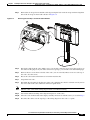
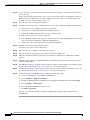
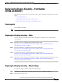
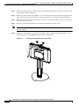
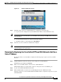
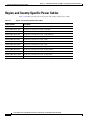
1
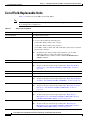
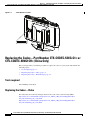
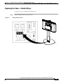
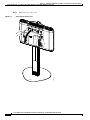
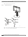
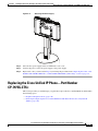
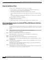
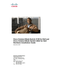
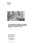
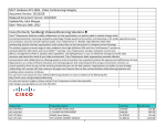
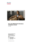
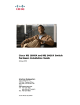
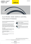
CH A P T E R
5
Field-Replaceable Units and Region- and
Country-Specific Power Cables
June 5, 2013, OL-23420-01
This chapter describes the tasks you perform to replace the Field-Replaceable Units (FRUs) for your
Cisco TelePresence System 500-32 (CTS-500-32) for first time use. This chapter also includes a list of
FRUs for the TelePresence system and region- and country-specific power cord information and includes
the following sections:
Note
•
List of Field-Replaceable Units, page 5-2
•
Finding the Serial Number Location, page 5-3
•
Replacing the Codec—Part Number CTS-CODEC-SING-G1= or CTS-CODEC-SING1CH= (China
Only), page 5-4
•
Replacing the Display Assembly—Part Number CTS500-32-INTDISP=, page 5-9
•
Replacing the Rear Camera Cover—Part Number CTS500-32-CAM-CVR=, page 5-12
•
Replacing the Camera Lens Cover—Part Number CTS500-32-LENSCVR=, page 5-14
•
Replacing the Microphone Cover—Part Number CTS500-32-MICCVRL= (Left) or
CTS500-32-MICCVRR= (Right), page 5-17
•
Replacing the Power Supply—Part Number CTS-CODEC-S-PWR=, page 5-18
•
Region-and Country-Specific Power Cables, page 5-24
The display used in this product contains mercury. Dispose of according to local, state, and federal laws.
Cisco TelePresence System 500-32 Installation, First-Time Setup, and Field-Replaceable Unit Guide
OL-23420-01
5-1
Chapter 5
Field-Replaceable Units and Region- and Country-Specific Power Cables
List of Field-Replaceable Units
List of Field-Replaceable Units
Table 5-1 contains a list of the FRUs for the CTS-500-32.
Note
Table 5-1
Most FRUs replace lost or broken items; optional items are listed as “Optional” and do not come with
the standard product configuration.
FRUs for the CTS-500-32
FRU
Description
CP-7975G-CTS=
Cisco IP Phone CP-7975G
CTS500-32-ACC-KIT=
Accessory kit
The accessory kit includes the following parts:
•
37-0887-02—RJ45-to-RJ45 cable, 3 meters
•
37-1025-01—RJ45-to-RJ45 cable, 8 meters
•
37-1210-01—VGA-to-VGA cable with 3mm audio connection (for external
presentations), 6 meters
Note
In addition to the VGA-to-VGA cable listed here, you can order
additional cables for video-only external presentations:
CTS-CABL-VGA-2= (VGA-to-VGA) or CTS-CAB-HDMIDVID2=
(HDMI-to-DVI-D)
CTS500-32-CABCVR=
Cable Sheath
CTS500-32-CAM-CVR=
Rear camera cover
Note
To replace this part, follow the procedure in the “Replacing the Rear
Camera Cover—Part Number CTS500-32-CAM-CVR=” section on
page 5-12.
CTS500-32-COD-CVR=
Codec cover
CTS500-32-CVRDOOR=
Codec cover port access door
CTS500-32-INTDISP=
Cisco TelePresence Integrated 32in Display without codec
Note
CTS500-32-LENSCVR=
Camera lens cover
Note
CTS500-32-MICCVRL=
To replace this part, follow the procedure in the “Replacing the Camera
Lens Cover—Part Number CTS500-32-LENSCVR=” section on
page 5-14.
Microphone cover, left
Note
CTS500-32-MICCVRR=
To replace this part, follow the procedure in the “Replacing the Display
Assembly—Part Number CTS500-32-INTDISP=” section on page 5-9.
To replace this part, follow the procedure in the “Replacing the
Microphone Cover—Part Number CTS500-32-MICCVRL= (Left) or
CTS500-32-MICCVRR= (Right)” section on page 5-17.
Microphone cover, right
Note
To replace this part, follow the procedure in the “Replacing the
Microphone Cover—Part Number CTS500-32-MICCVRL= (Left) or
CTS500-32-MICCVRR= (Right)” section on page 5-17.
Cisco TelePresence System 500-32 Installation, First-Time Setup, and Field-Replaceable Unit Guide
5-2
OL-23420-01
Chapter 5
Field-Replaceable Units and Region- and Country-Specific Power Cables
Finding the Serial Number Location
Table 5-1
FRUs for the CTS-500-32 (continued)
FRU
Description
CTS500-32-PED=
Pedestal (Stand-Mount only)
CTS500-32-PEDCOL=
Column for table stand (Table-Mounted systems only)
CTS500-32-TABMT=
Table mount
Note
Order this FRU to convert your system from a pedestal-mounted to a
table-mounted system.
CTS-CABCVR-FLR=
Cable cover floor mat (Optional)
CTS-CAB-HDMIDVID2=
HDMI to DVI-D external presentation cable, 2 meters (Optional)
CTS-CABL-VGA-2=
VGA-to-VGA external presentation cable, 2 meters
CTS-CAB-MGMTCUP=
External presentation cable holder (table-mounted cable cup) (Optional)
CTS-CAM-TOOL-G2=
Camera targets (small and large) (Optional)
CTS-CODEC-SING1CH=
Codec (China only)
Note
CTS-CODEC-SING-G1=
Codec
Note
CTS-CODEC-S-PWR=
To replace this part, follow the procedure in the “Replacing the
Codec—Part Number CTS-CODEC-SING-G1= or
CTS-CODEC-SING1CH= (China Only)” section on page 5-4.
To replace this part, follow the procedure in the “Replacing the
Codec—Part Number CTS-CODEC-SING-G1= or
CTS-CODEC-SING1CH= (China Only)” section on page 5-4.
Power supply
Finding the Serial Number Location
You might need the serial number of your CTS 500-32 to order FRUs. The serial number is located on
the rear of the display as shown in Figure 5-1.
Cisco TelePresence System 500-32 Installation, First-Time Setup, and Field-Replaceable Unit Guide
OL-23420-01
5-3
Chapter 5 Field-Replaceable Units and Region- and Country-Specific Power Cables
Replacing the Codec—Part Number CTS-CODEC-SING-G1= or CTS-CODEC-SING1CH= (China Only)
Figure 5-1
Serial Number Location
343340
SN: XXXNNNNXXXX
Replacing the Codec—Part Number CTS-CODEC-SING-G1= or
CTS-CODEC-SING1CH= (China Only)
This section provides you with the procedure to replace the codec for your system and includes the
following topics:
•
Tools required, page 5-4
•
Replacing the Codec—Video, page 5-4
•
Replacing the Codec—Detailed Steps, page 5-5
Tools required
One #2 Phillips screwdriver
Replacing the Codec—Video
For videos that show removal and replacement of the codec, refer to the following URLs:
http://www.cisco.com/en/US/docs/telepresence/cts_500/cts_500_32/assembly/guide/video/
fru_videos/removing_the_codec.html
http://www.cisco.com/en/US/docs/telepresence/cts_500/cts_500_32/assembly/guide/video/
fru_videos/installing_the_codec.html
Cisco TelePresence System 500-32 Installation, First-Time Setup, and Field-Replaceable Unit Guide
5-4
OL-23420-01
Chapter 5
Field-Replaceable Units and Region- and Country-Specific Power Cables
Replacing the Codec—Part Number CTS-CODEC-SING-G1= or CTS-CODEC-SING1CH= (China Only)
Replacing the Codec—Detailed Steps
To replace the codec, complete the following steps.
Step 1
Figure 5-2
Turn the On/Off switch to the Off position.
On/Off Switch Location
Aux
PC
208933
INPUT: 100-240V~, 5A, 50/50Hz
Cisco TelePresence System 500-32 Installation, First-Time Setup, and Field-Replaceable Unit Guide
OL-23420-01
5-5
Chapter 5 Field-Replaceable Units and Region- and Country-Specific Power Cables
Replacing the Codec—Part Number CTS-CODEC-SING-G1= or CTS-CODEC-SING1CH= (China Only)
Step 2
Removing the Codec Cover
209093
Figure 5-3
Remove the rear codec cover.
Cisco TelePresence System 500-32 Installation, First-Time Setup, and Field-Replaceable Unit Guide
5-6
OL-23420-01
Chapter 5
Field-Replaceable Units and Region- and Country-Specific Power Cables
Replacing the Codec—Part Number CTS-CODEC-SING-G1= or CTS-CODEC-SING1CH= (China Only)
Step 3
Figure 5-4
Remove the tie-wraps from around the cables by pressing the latch on the tie-wraps and removing them.
One of the tie-wraps is shown with callout 1 in Figure 5-4.
Removing the Tie Wraps around the Cable Bundles
209094
1
Step 4
Detach the cables from the codec. Make a note of each cable connection. You can use the tape flags on
the cables for this purpose. If your cables do not have tape flags, you can make some with masking tape.
Step 5
Remove the two screws from each side of the codec (one on each side). These screws are at the top of
the codec. Save the screws.
Step 6
Rotate the codec backward and remove it from the metal bracket.
Step 7
Unpack the new codec.
Step 8
Determine the placement of the diagram on the codec and make sure that it is oriented correctly and on
the correct side of the codec and that it will not be upside-down.
Note
The new codec comes with a wiring diagram with a self-adhesive backing.
Step 9
Peel off the adhesive backing on the diagram and place it on the codec.
Step 10
Place the codec in the bracket in the display assembly and secure it with the screws you saved in Step 5.
Step 11
Reconnect the cables. Use the tape flags or the wiring diagram on the codec as a guide.
Cisco TelePresence System 500-32 Installation, First-Time Setup, and Field-Replaceable Unit Guide
OL-23420-01
5-7
Chapter 5 Field-Replaceable Units and Region- and Country-Specific Power Cables
Replacing the Codec—Part Number CTS-CODEC-SING-G1= or CTS-CODEC-SING1CH= (China Only)
Step 12
Use the tie-wraps to route and rearrange the cables. Callout 1 in Figure 5-4 shows the location of one of
the two tie-wrap.
Correct cable routing ensures that the codec cover can be placed on the rear of the display. Therefore,
make sure that the cables do not cover the mounting holes for the codec cover, and that they do not
protrude so that you cannot attach the codec cover.
Step 13
Place the rear codec cover back on the display.
Step 14
Complete the following steps to configure the new codec in Cisco Unified Communications Manager:
Step 15
a.
Open a browser on a computer connected to the network.
b.
Access the Cisco Unified Communications Manager interface.
c.
Add the Room Email ID of the previous codec to the new codec.
d.
Make sure the new codec's status is registered.
e.
Delete the MAC address of the previous codec from the Cisco Unified CM application user profile
that is used in Cisco TelePresence Manager (CTS-Manager).
f.
Add the new codec to the application user profile and click Save.
Turn the codec power switch to the On position.
See Figure 5-2 for the location of this switch.
Step 16
Open a browser on a computer connected to the network.
Step 17
Type the IP address of the primary codec unit into the browser address bar.
Step 18
Enter the required information at the login screen. The Cisco TelePresence Administrator window
appears.
Step 19
Verify the status of the Cisco Unified Communications Manager (seen in the lower left portion of the
window) is Enabled/Up.
Step 20
Select Hardware Setup to verify the cameras, displays, speakers, and microphones are working properly.
See the “Manual First-Time Setup” section on page 4-31 for more information.
Step 21
Perform the Auto Adjust camera setup procedure. This sets the white balance to the correct levels. See
the “Manual First-Time Setup” section on page 4-31 for more information.
Step 22
Configure the codec in CTS-Manager by completing the following steps:
a.
Log in to CTS-Manager as SysAdmin or Administrator.
b.
Go to Configure > Application Settings.
c.
Disable the Meeting Notification Email by selecting No for Enable Feature and clicking Apply.
d.
Go to Configure > Unified CM.
e.
Select the Unified CM that has the new codec.
f.
Click Discover Rooms.
The new codec with the existing room name is added and the previous codec is removed from
CTS-Manager.
Cisco TelePresence System 500-32 Installation, First-Time Setup, and Field-Replaceable Unit Guide
5-8
OL-23420-01
Chapter 5
Field-Replaceable Units and Region- and Country-Specific Power Cables
Replacing the Display Assembly—Part Number CTS500-32-INTDISP=
Replacing the Display Assembly—Part Number
CTS500-32-INTDISP=
The following section provides you with the procedure to replace the display and includes the following
topics:
•
Tools required, page 5-9
•
Replacing the Display Assembly—Video, page 5-9
•
Replacing the Display Assembly—Detailed Steps, page 5-9
Tools required
One #2 Phillips screwdriver
Note
Two people are required for installation to remove the display assembly from the column.
Replacing the Display Assembly—Video
For videos that show removal and replacement of the display, complete the tasks as shown in the
following URL.
Step 1
Remove the codec by completing the tasks in the following video:
http://www.cisco.com/en/US/docs/telepresence/cts_500/cts_500_32/assembly/guide/video/
fru_videos/removing_the_codec.html
Step 2
Remove the display by completing the tasks in the following video:
http://www.cisco.com/en/US/docs/telepresence/cts_500/cts_500_32/assembly/guide/video/
fru_videos/removing_the_display.html
Step 3
Install the new display by completing the tasks in the following video:
http://www.cisco.com/en/US/docs/telepresence/cts_500/cts_500_32/assembly/guide/video/
fru_videos/installing_the_display.html
Step 4
Replace the existing codec into the new display assembly by completing the tasks in the following video:
http://www.cisco.com/en/US/docs/telepresence/cts_500/cts_500_32/assembly/guide/video/
fru_videos/installing_the_codec.html
Replacing the Display Assembly—Detailed Steps
To replace the display assembly, complete the following steps:
Step 1
Turn off the system using the on/off switch on the bottom of the column (near the floor).
Step 2
Remove the rear codec cover.
Cisco TelePresence System 500-32 Installation, First-Time Setup, and Field-Replaceable Unit Guide
OL-23420-01
5-9
Chapter 5
Replacing the Display Assembly—Part Number CTS500-32-INTDISP=
Field-Replaceable Units and Region- and Country-Specific Power Cables
Step 3
Remove the tie-wraps from around the cables by pressing the latch on the tie-wraps. One of the tie-wraps
is shown with callout 1 in Figure 5-4.
Step 4
Detach the cables from the codec. Make a note of each cable position. You can use the tape flags on the
cables for this purpose. If your cables do not have tape flags, you can make some with masking tape.
Step 5
Remove the two screws from each side of the codec (one on each side). These screws are at the top of
the codec. Save the screws.
Step 6
Rotate the codec backward and remove it from the metal bracket. Save the codec.
Note
Step 7
You do NOT have to remove the power supply behind the codec; another one is supplied with the new
display assembly.
Take the two cable bundles on each side of the display and route them downward behind the codec
bracket, until the two cable bundles hang on each side of the stand.
Routing the Cables Behind the Codec Bracket
209095
Figure 5-5
Cisco TelePresence System 500-32 Installation, First-Time Setup, and Field-Replaceable Unit Guide
5-10
OL-23420-01
Chapter 5
Field-Replaceable Units and Region- and Country-Specific Power Cables
Replacing the Display Assembly—Part Number CTS500-32-INTDISP=
Step 8
Figure 5-6
Loosen the screws that attach the display assembly to the column and pull the display off the column.
Removing the Display From the Column
510802
Step 9
Unpack the new display assembly.
Step 10
Put the new assembly back on the column and route the cable bundles upward behind the codec bracket.
Note
Attachment of the display is the same procedure as removal, with the steps performed in reverse.
Step 11
Tighten the screws that attach the display to the column. The screws are shown in Figure 5-6.
Step 12
Place the codec back in the bracket in the display assembly and secure it with the screws you saved in
Step 5.
Step 13
Reconnect the cables. Use the tape flags or the wiring diagram on the codec as a guide.
Step 14
Use the tie-wraps to route the cables.
Correct cable routing ensures that the codec cover can be placed on the rear of the display. Therefore,
make sure that the cables do not cover the mounting holes for the codec cover, and that they do not
protrude so that you cannot attach the codec cover.
Step 15
Place the rear codec cover back on the display.
Step 16
Follow these steps to configure the new codec in Cisco Unified Communications Manager:
a.
Open a browser on a computer connected to the network.
b.
Access the Cisco Unified Communications Manager interface.
c.
Add the Room Email ID of the previous codec to the new codec.
d.
Make sure the new codec's status is registered.
Cisco TelePresence System 500-32 Installation, First-Time Setup, and Field-Replaceable Unit Guide
OL-23420-01
5-11
Chapter 5
Replacing the Rear Camera Cover—Part Number CTS500-32-CAM-CVR=
Field-Replaceable Units and Region- and Country-Specific Power Cables
e.
Delete the MAC address of the previous codec from the Cisco Unified CM application user profile
that is used in CTS-Manager.
f.
Add the new codec to the application user profile and click Save.
Step 17
Power on the system by turning the power switches to the On position on the two left PDUs, single right
PDU, and (if present) auxiliary control unit or PDU on the rear center of the display assembly.
Step 18
Open a browser on a computer connected to the network.
Step 19
Type the IP address of the codec into the browser address bar.
Step 20
Enter the required information at the login screen. The Cisco TelePresence Administrator window
appears.
Step 21
Verify the status of the Cisco Unified Communications Manager (seen in the lower left portion of the
window) is Enabled/Up.
Step 22
Select Hardware Setup to verify the cameras, displays, speakers, and microphones are working
properly. For more information, see the “Manual First-Time Setup” section on page 4-31
Step 23
Perform the Auto Adjust camera setup procedure. This sets the white balance to the correct levels. See
the “Setting Up the Camera” section on page 4-33 for detailed instructions.
Step 24
Configure the codec in CTS-Manager by completing the following steps:
a.
Log in to CTS-Manager as SysAdmin or Administrator.
b.
Go to Configure > Application Settings.
c.
Disable the Meeting Notification Email by selecting No for Enable Feature and clicking Apply.
d.
Go to Configure > Unified CM.
Step 25
Select the Unified CM that has the new codec.
Step 26
Click Discover Rooms.
The new codec with the existing room name is added and the previous codec is removed from
CTS-Manager.
Replacing the Rear Camera Cover—Part Number
CTS500-32-CAM-CVR=
To replace the rear camera cover, complete the following steps:
Step 1
Unscrew the two screws that secure the rear camera cover to the display assembly.
Step 2
Unlatch the latch on the underside of the cover and lift it off the display assembly.
Cisco TelePresence System 500-32 Installation, First-Time Setup, and Field-Replaceable Unit Guide
5-12
OL-23420-01
Chapter 5
Field-Replaceable Units and Region- and Country-Specific Power Cables
Replacing the Rear Camera Cover—Part Number CTS500-32-CAM-CVR=
Removing the Rear Camera Cover
209096
Figure 5-7
Step 3
Attachment of the new rear camera cover is the opposite of removal. Place the cover on the display
assembly and secure it with the screws.
Cisco TelePresence System 500-32 Installation, First-Time Setup, and Field-Replaceable Unit Guide
OL-23420-01
5-13
Chapter 5
Replacing the Camera Lens Cover—Part Number CTS500-32-LENSCVR=
Field-Replaceable Units and Region- and Country-Specific Power Cables
Replacing the Camera Lens Cover—Part Number
CTS500-32-LENSCVR=
To replace the camera lens cover, complete the following steps:
Step 1
Log in to the Cisco TelePresence System (CTS) by completing the following steps:
Open a browser and type in the IP address of the system in the URL and press Enter.
Step 2
a.
In the Admin field, type admin.
b.
In the Password field, type cisco.
c.
Click Login.
d.
Navigate to Troubleshooting > Hardware Setup > Cameras.
Click Start.
The camera drops from its enclosure.
Step 3
Unscrew the screw that attaches the camera lens cover to the display assembly.
Cisco TelePresence System 500-32 Installation, First-Time Setup, and Field-Replaceable Unit Guide
5-14
OL-23420-01
Chapter 5
Field-Replaceable Units and Region- and Country-Specific Power Cables
Replacing the Camera Lens Cover—Part Number CTS500-32-LENSCVR=
Step 4
Removing the Camera Lens Cover
209103
Figure 5-8
Remove the camera lens cover.
Cisco TelePresence System 500-32 Installation, First-Time Setup, and Field-Replaceable Unit Guide
OL-23420-01
5-15
Chapter 5
Replacing the Camera Lens Cover—Part Number CTS500-32-LENSCVR=
Step 5
Attach the new camera lens cover to the system.
Attaching the Camera Lens Cover
209097
Figure 5-9
Field-Replaceable Units and Region- and Country-Specific Power Cables
Step 6
In the Cisco TelePresence Administrative GUI, click Stop to retract the camera back into its enclosure.
Step 7
Log out of the Cisco TelePresence Administrative GUI.
Cisco TelePresence System 500-32 Installation, First-Time Setup, and Field-Replaceable Unit Guide
5-16
OL-23420-01
Chapter 5
Field-Replaceable Units and Region- and Country-Specific Power Cables
Replacing the Microphone Cover—Part Number CTS500-32-MICCVRL= (Left) or CTS500-32-MICCVRR= (Right)
Replacing the Microphone Cover—Part Number
CTS500-32-MICCVRL= (Left) or CTS500-32-MICCVRR= (Right)
To remove the microphone cover, grasp the microphone cover by its edges near the camera lens and pull
outward. Installation is the opposite of removal.
Removing the Speaker Cover
209098
Figure 5-10
Cisco TelePresence System 500-32 Installation, First-Time Setup, and Field-Replaceable Unit Guide
OL-23420-01
5-17
Chapter 5
Field-Replaceable Units and Region- and Country-Specific Power Cables
Replacing the Power Supply—Part Number CTS-CODEC-S-PWR=
Replacing the Power Supply—Part Number
CTS-CODEC-S-PWR=
This section provides you with the procedure to replace the codec for your system and includes the
following topics:
•
Tools required, page 5-18
•
Replacing the Power Supply, page 5-18
Tools required
One #2 Phillips screwdriver
Replacing the Power Supply
To remove the power supply, complete the following steps:
Step 1
Remove the codec by following the procedure in the “Replacing the Codec—Part Number
CTS-CODEC-SING-G1= or CTS-CODEC-SING1CH= (China Only)” section on page 5-4.
Step 2
Disconnect the power cord from the power supply. The cord is on the top of the supply.
Step 3
Pull the power supply out from behind the codec cover.
Cisco TelePresence System 500-32 Installation, First-Time Setup, and Field-Replaceable Unit Guide
5-18
OL-23420-01
Chapter 5
Field-Replaceable Units and Region- and Country-Specific Power Cables
Replacing the Cisco Unified IP Phone—Part Number CP-7975G-CTS=
Removing the Power Supply
209270
Figure 5-11
Step 4
Place the new power supply in the slot behind the codec cover.
Step 5
Connect the power cord to the power supply to the power supply.
Step 6
Replace the codec you removed in Step 1 by following the procedure in the “Replacing the Codec—Part
Number CTS-CODEC-SING-G1= or CTS-CODEC-SING1CH= (China Only)” section on page 5-4.
Replacing the Cisco Unified IP Phone—Part Number
CP-7975G-CTS=
This section provides you with the steps you perform to replace the Cisco Unified IP Phone and includes
the following topics:
•
Required and Optional Tools, page 5-20
•
Removing the Replacing the Cisco Unified IP Phone With Networks that Use a Dynamic IP
Address, page 5-20
Cisco TelePresence System 500-32 Installation, First-Time Setup, and Field-Replaceable Unit Guide
OL-23420-01
5-19
Chapter 5
Replacing the Cisco Unified IP Phone—Part Number CP-7975G-CTS=
Field-Replaceable Units and Region- and Country-Specific Power Cables
Required and Optional Tools
To replace the Cisco Unified IP Phone, the following tools are required:
•
Laptop computer (for connecting to the Cisco TelePresence Administration Software and
Cisco Unified Communications Manager (Unified CM) GUIs)
•
RJ45 Ethernet straight through patch cable (for the laptop-to-codec connection
•
Customer Unified CM administrator IP or DNS address, ID, and password (to configure Unified
CM)
•
Customer Cisco TelePresence administrator IP or DNS address, ID, and password (to configure the
Cisco TelePresence Administration software)
The following items are optional but recommended:
•
Phillips and flat head screwdrivers
•
Cable marker (tape flags or another method) for labeling the device and Ethernet cables
Removing the Replacing the Cisco Unified IP Phone With Networks that Use a
Dynamic IP Address
If your network uses the Dynamic Host Configuration Protocol (DHCP) to dynamically allocate an IP
address for your Cisco TelePresence system, complete the following steps to replace your Cisco Unified
IP Phone.
Step 1
Unplug the Ethernet cable from the back of the existing Cisco Unified IP Phone.
The Ethernet port is marked as 10/100 SW.
Step 2
Make a note of the MAC Address of the new Cisco Unified IP Phone.
Find the MAC address on a white sticker on the rear of the phone, next to the Ethernet port.
Step 3
Log in to the Unified CM Administrative GUI.
Step 4
Enter the MAC address of the new Cisco Unified IP phone into the Administrative GUI.
The phone settings are stored in Unified CM and the MAC address is required for the phone to register
with Unified CM.
Step 5
Connect the new Cisco Unified IP Phone to the Ethernet cable to the 10/100 SW port (the same port as
was used on the existing phone).
The IP phone starts booting with the Power over Ethernet (PoE) power provided by the TelePresence
codec and attempts to register with Unified CM.
Step 6
Wait for the phone to complete its bootup procedure.
After the IP phone has successfully booted up and registered with the Call Manager, the IP phone ready
screen will display. See Figure 5-12 for an example of this screen.
Cisco TelePresence System 500-32 Installation, First-Time Setup, and Field-Replaceable Unit Guide
5-20
OL-23420-01
Chapter 5
Field-Replaceable Units and Region- and Country-Specific Power Cables
Replacing the Cisco Unified IP Phone—Part Number CP-7975G-CTS=
Figure 5-12
Step 7
Check the status of the Cisco Unified IP Phone by completing the following steps:
a.
Tip
Step 8
Note
IP Phone TelePresence Screen
Log in to the Cisco Telepresence System Administration GUI to verify the IP Phone status.
To find TelePresence system IP address, press the More softkey, then press the Info softkey on the Cisco
Unified IP Phone.
b.
Look in the System Status area on the lower left of the window.
c.
Determine if there is a check mark next to Room Phone.
Perform a test call to another Cisco TelePresence endpoint.
If the IP phone fails registering with Unified CM, contact your Unified CM administrator or your
authorized TelePresence representative.
Removing the Replacing the Cisco Unified IP Phone With Networks that Use a
Static IP Address
If your network uses a static IP address complete the following steps to replace your Cisco Unified
IP Phone.
Step 1
Unplug the Ethernet cable from the back of the existing Cisco Unified IP Phone.
The Ethernet port is marked as 10/100 SW.
Step 2
Make a note of the MAC Address of the new Cisco Unified IP Phone.
Find the MAC address on a white sticker on the rear of the phone, next to the Ethernet port.
Step 3
Log in to the Unified CM Administrative GUI.
Step 4
Enter the MAC address of the new Cisco Unified IP phone into the Administrative GUI.
The phone settings are stored in Unified CM and the MAC address is required for the phone to register
with Unified CM.
Cisco TelePresence System 500-32 Installation, First-Time Setup, and Field-Replaceable Unit Guide
OL-23420-01
5-21
Chapter 5
Replacing the Cisco Unified IP Phone—Part Number CP-7975G-CTS=
Step 5
Field-Replaceable Units and Region- and Country-Specific Power Cables
Connect the new Cisco Unified IP Phone to the Ethernet cable to the 10/100 SW port (the same port as
was used on the existing phone).
The IP phone starts booting with the PoE provided by the TelePresence codec and attempts to register
with Unified CM.
Wait for the phone to become active.
Step 6
Press the Settings button on your Cisco Unified IP Phone.
Figure 5-13
Step 7
Note
Settings Button
Using the Up and Down arrows on the phone, scroll down until you highlight the Network Configuration
option.
Do not press the Select softkey yet.
Step 8
Press **# (Star-Star-Pound) to unlock the network setting parameter.
Step 9
The phone displays the following message on bottom of the screen.
Settings Unlocked!
In addition, an unlocked icon appears on the top right of the screen.
Step 10
Press the Select softkey.
Step 11
Select IPv4 configuration and press the Select softkey.
Step 12
Using the up and down arrows on the phone, scroll to the DHCP selection. ‘
Step 13
Press the No softkey.
Step 14
Press the Save softkey.
Step 15
Scroll to the IP address selection and press the Edit softkey.
Step 16
Enter the static IP address for the Cisco Unified IP phone.
Step 17
Press the Validate softkey.
Step 18
Scroll to the Subnet Mask selection and press the Edit softkey.
Step 19
Enter the subnet mask for your static IP address.
Step 20
Press the Validate softkey.
Step 21
Scroll to the Default Router selection and press the Edit softkey.
Step 22
Enter the IP address of the IP gateway (default router).
Step 23
Press the Validate softkey.
Step 24
Scroll to the TFTP server 1 selection and press the Edit softkey.
Step 25
Enter the IP address of the TFTP server.
Step 26
Press the Validate softkey.
Step 27
(Optional) scroll to the TFTP server 2 selection and press the Edit softkey.
Step 28
Enter the IP address of the alternate TFTP server.
Step 29
Press the Validate softkey.
Cisco TelePresence System 500-32 Installation, First-Time Setup, and Field-Replaceable Unit Guide
5-22
OL-23420-01
Chapter 5
Field-Replaceable Units and Region- and Country-Specific Power Cables
Replacing the Cisco Unified IP Phone—Part Number CP-7975G-CTS=
Step 30
Press the Save softkey to save your changes.
After the configuration is saved, the IP phone will display the following text:
Updating CTL
Step 31
Press **# (Star-Star-Pound) to lock your phone configuration.
The Cisco Unified IP Phone reloads and bring up the Cisco TelePresence screen.
Step 32
Wait for the phone to complete its bootup procedure.
After the IP phone has successfully booted up and registered with the Call Manager, the IP phone ready
screen will display. See Figure 5-12 for an example of this screen.
Figure 5-14
Step 33
Check the status of the Cisco Unified IP Phone by completing the following steps:
a.
Tip
IP Phone TelePresence Screen
Log in to the Cisco Telepresence System Administration GUI to verify the IP Phone status.
To find TelePresence system IP address, press the More softkey, then press the Info softkey on the Cisco
Unified IP Phone.
b.
Look in the System Status area on the lower left of the window.
c.
Determine if there is a check mark next to Room Phone.
Cisco TelePresence System 500-32 Installation, First-Time Setup, and Field-Replaceable Unit Guide
OL-23420-01
5-23
Chapter 5
Field-Replaceable Units and Region- and Country-Specific Power Cables
Region-and Country-Specific Power Cables
Region-and Country-Specific Power Cables
Table 5-2 provides you with a list of the region- and country-specific power cables.
Table 5-2
Region- and Country-Specific Power Cables
Power Cord ID
Description
PWR-CORD-G2A-AP=
TelePresence G2A Power Cords - Asia Pacific
PWR-CORD-G2A-AR=
TelePresence G2A Power Cords - Argentina
PWR-CORD-G2A-AU=
TelePresence G2A Power Cords - Australia
PWR-CORD-G2A-CE=
TelePresence G2A Power Cords - Central Europe
PWR-CORD-G2A-CN=
TelePresence G2A Power Cords - China
PWR-CORD-G2A-ID=
TelePresence G2A Power Cords - India
PWR-CORD-G2A-ISR=
TelePresence G2A Power Cords - Israel
PWR-CORD-G2A-ITA=
TelePresence G2A Power Cords - Italy
PWR-CORD-G2A-JP=
TelePresence G2A Power Cords - Japan
PWR-CORD-G2A-NA=
TelePresence G2A Power Cords - North America
PWR-CORD-G2A-SA=
TelePresence G2A Power Cords - South Africa
PWR-CORD-G2A-SWI=
TelePresence G2A Power Cords - Switzerland
PWR-CORD-G2A-UK=
TelePresence G2A Power Cords - United Kingdom and United Arab Emirates
Cisco TelePresence System 500-32 Installation, First-Time Setup, and Field-Replaceable Unit Guide
5-24
OL-23420-01