1
Dell Networking
C-Series Systems
Quick Start Guide
Regulatory Model: C7004/C7008
Dell Networking
C-Series Systems
Quick Start Guide
Regulatory Model:C7004/C7008
Notes, Cautions, and Warnings
NOTE: A NOTE indicates important information that helps you make better use
of your computer.
CAUTION: A CAUTION indicates potential damage to hardware or loss of
data if instructions are not followed.
WARNING: A WARNING indicates a potential for property damage,
personal injury, or death.
If you purchased a Dell Series computer, any references in this publication to
Microsoft Windows operating systems are not applicable.
____________________
Information in this publication is subject to change without notice.
© 2014 Dell Inc. All rights reserved.
Reproduction of these materials in any manner whatsoever without the written permission of Dell Inc.
is strictly forbidden.
Copyright © 2014 Dell Inc. All rights reserved. This product is protected by U.S. and international
copyright and intellectual property laws. Dell and the Dell logo are trademarks of Dell Inc. in the
United States and/or other jurisdictions. All other marks and names mentioned herein may be
trademarks of their respective companies.
Regulatory Model: C7004/C7008
2014 - 01
P/N 0JVTD9 Rev. A02
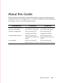
About this Guide
This document is intended as a Quick Start Guide to get new systems up and
running and ready for configuration. For complete installation and configuration
information, refer to the following documents:
Documentation
C7004/C150
C7008/C300
Hardware installation and
power-up instructions
Installing and Maintaining Installing and Maintaining
the C7004/C150 System
the C7008/C300 System
Software configuration
Dell Networking OS
Configuration Guide
Dell Networking OS
Configuration Guide
Command line interface
Dell Networking OS
Command Line Reference
Guide
Dell Networking OS
Command Line Reference
Guide
Latest updates
Dell Networking OS
Dell Networking OS
Release Notes for C-Series Release Notes for C-Series
About this Guide
3
1
Installing the Hardware
This guide assumes all site preparation has been performed before installing the
chassis.
Installing the Chassis
To install the C7004/C150 and the C7008/C300 chassis, Dell Networking
recommends completing the installation procedures in the order presented
below.
NOTE: Unless stated otherwise, the installation instructions apply to both the
C7004/C150 and C7008/C300 chassis.
Always handle the system and its components with care. Avoid dropping the
switch or its field replaceable units (FRUs).
CAUTION: Always wear an electrostatic discharge (ESD)-preventive wrist or
heel ground strap when handling the chassis and its components. As with all
electrical devices of this type, take all necessary safety precautions to prevent
injury when installing this system. ESD damage can occur if components are
mishandled.
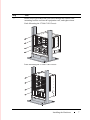
Installing the Chassis in a Two-Post Rack
WARNING: Use an equipment lift or pallet jack when lifting or moving the
chassis. Install the chassis into the rack before inserting chassis components.
Lift the chassis only from the bottom. Lifting by the chassis shelves or power
supply openings might damage the chassis.
WARNING: To prevent bodily injury when mounting or servicing this unit in
a rack, take special precautions to ensure that the system remains stable. The
following guidelines are provided to ensure your safety:
•
Mount this unit at the bottom of the rack if it is the only unit in the rack.
•
When mounting this unit in a partially filled rack, load the rack from the
bottom to the top with the heaviest component at the bottom of the rack.
•
If the rack is provided with stabilizing devices, install the stabilizers
before mounting or servicing the unit in the rack.
Installing the Hardware
5
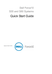
Follow these steps to install the chassis into a 19-inch equipment rack:
Step
6
Task
1
Determine the chassis mounting location in the equipment rack.
2
Orient the bar with the arrows pointing upward. The smooth side of the
bar should face outward.
3
Attach the bar to the equipment rack brackets using the mounting screws
provided by the rack manufacturer.
4
Use an equipment lift to align the chassis rack-mount holes with the
equipment rack holes, and situate the chassis on top of the equipment
rack bar.
Installing the Hardware
Step
5
Task
Insert screws (provided with your rack) through the chassis rackmounting bracket and into the equipment rack, and tighten them.
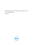
Rack Mounting the C7004/C150 Chassis
Rack Mounting the C7008/C300 Chassis
Installing the Hardware
7
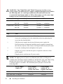
Installing Power Modules
CAUTION: Do not install the Power Supply 1200W-AC and Power Supply
1600W-AC in the same chassis. The line cards will power down and data may
be lost.
If there is a failure in the power supply, you must replace it. Power supplies are
not field serviceable.
The C7004/C150 has six power supply slots at the front-bottom of the chassis.
The C7008/C300 has eight power supply slots at the front-bottom of the chassis.
The slots accept either the 1200W or 1600W AC power supply units (PSUs).
AC Power Supplies
• There are two types of power supplies: Power Supply 1200W-AC and Power
Supply 1600W-AC. The minimum and redundant power supplies required to
operate are listed in the table below. Dell Networking recommends the
redundancy configuration.
•
The following table lists the PSU requirements for Dell Networking OS
version 8.4.5.0 or prior. 1600W-AC PSU is recognized by version 8.4.5.0 or
later.
C7004/C150
C7008/C300
8
Voltage Minimum
PSUs
Minimum with
Redundant
PSUs
Power Supply 1200WAC/Power Supply
1600W-AC
100-120 Configuration
Dependent
Configuration
Dependent
200-240 Configuration
Dependent
Configuration
Dependent
Power Supply 1200WAC/Power Supply
1600W-AC
100-120 Configuration
Dependent
Configuration
Dependent
Power Supply 1200W-AC 200-240 Configuration
Dependent
Configuration
Dependent
Power Supply 1600W-AC 200-240 Configuration
Dependent
Configuration
Dependent
Installing the Hardware
For Dell Networking OS version 8.4.6.0, the minimum PSUs required for system power is based on
the power requirements of the RPMs, the line cards, and the type of fan tray present in the chassis.
System Power Required = Power required for 2 RSMs + Power Required for Fan Tray + Power
required for Line cards in the system.
Number of PSUs Required for System Power = System Power Required /90% of PSU power
For power requirements corresponding to different components, refer to Installing and Maintaining the C7004/C150 System and Installing and Maintaining the C7008/C300 System.
If N PSUs are required for system power, then N+1 th PSU is reserved for redundant system power.
For details corresponding to PoE power availability, refer to Power Over Ethernet section of Dell
Networking OS Configuration Guide.
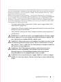
•
To protect against high-voltage shock, install a power supply blank on all
unused power supply slots.
•
Connect the AC power supply to the appropriate branch circuit protection as
defined by local electrical codes.
•
Verify that the remote power source complies with the system input power
specifications.
WARNING: Use only the AC power cord supplied with the AC power supply.
Do not supply power to your system until you install the power supplies, fan
tray, route processor modules (RPMs), and line cards.
WARNING: This product relies on the building's installation for short-circuit
(overcurrent) protection. Ensure you use a fuse or circuit breaker no larger
than 120 VAC, 15A U.S. (240 VAC, 10A international) on the phase conductors
(all current-carrying conductors).
WARNING: The C7008/C300 does not have a main disconnect device
installed. It is the responsibility of the installer to provide a suitable
disconnecting device in the building installation and ensure that it is
located/installed near the equipment and is easily accessible.
WARNING: Do not install the Power Supply 1200W-AC and Power Supply
1600W-AC in the same chassis. The line cards will power down and data may
be lost.
Installing the Hardware
9
WARNING: The C7008/C300 and C7004/C150 operates in either of two
voltage ranges. The different power supply configuration supported is listed in
the following table. As a safety precaution, do not install more than the
recommended maximum number of PSUs (shown below), as this causes high
leakage current. Install blank panels in all unused PSU slots.
Voltage
Frequency
Maximum PSUs
C7004/C150 100-120
50/60Hz
5 primary + 1 redundant
200-240
50/60Hz
5 primary + 1 redundant
C7008/C300 100-120
50/60Hz
7 primary + 1 redundant
200-240
50/60Hz
7 primary + 1 redundant
Step
Task
1
Verify the power switch is in the OFF (left) position.
2
Secure the retaining latch in the unlatched position by tightening the
screw into the threaded hole.
3
Slide the power supply into the top left-most power supply slot.
Dell Networking recommends installing power supplies starting from
the left side, top row of the chassis, leaving no blank slots between units.
4
Lower the retaining latch, and tighten it into place.
5
Plug the AC power cord into the power receptacle in the face of the
power supply.
6
Plug the power cord into an AC power outlet.
NOTE: The higher power of power over Ethernet plus (PoE+) (30W/port) is
available only with Power Supply 1600W-AC and the PoE+ line card. When using
the PoE line card or PoE+ line card and the Power Supply 1200W-AC, only
15.4W/port power is available. The maximum power per port is listed in the
following table.
PoE line card
Power Supply
1200W-AC
Power Supply
1600W-AC at
lowline (100-120V)
Power Supply
1600W-AC at
highline (200-240V)
15.4W/port
15.4W/port
15.4W/port
30W/port
30W/port
PoE+ line card 15.4W/port
10
Installing the Hardware
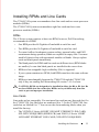
Installing RPMs and Line Cards
The C7004/C150 system accommodates four line cards and two route processor
modules (RPMs).
The C7008/C300 System accommodates eight line cards and two route
processor modules (RPMs).
RPMs
The C-Series system requires at least one RPM; however, Dell Networking
recommends two RPMs.
•
One RPM provides 48 Gigabits of bandwidth to each line card.
•
Two RPMs provides 96 Gigabits of bandwidth to each line card.
•
To control airflow for adequate system cooling, personal safety, and EMI
containment during operation, blanks are required in empty slots. You must
install all chassis slots with operational modules or blanks. Always replace
cards and blank panels immediately.
•
The blank panels for RPMs and line cards are different sizes (RPM blanks
are smaller); be sure that blank panels are installed in the correct slots.
•
RPMs are hot-swappable. high availability (HA) is supported.
•
If your system contains two RPMs, both RPMs must have the same software
image.
•
RPMs are interchangable between the C7008/C300 and the C7004/C150
only if they are running Dell Networking OS version 7.6.1.0 or later.
CAUTION: RPMs are designed to be installed in either the R0 or R1 slot. Do
not force RPMs into line cards slots. RPMs are keyed differently than line
cards to prevent improper installation.
Line Cards
Line cards are hot-swappable. You can insert line card into any line card slot. On
the C7004/C150, line card slots are numbered 0 to 3. On the C7008/C300, line
card slots are labeled 0 to 7. You can see the slot numbering labels when you
install the fan tray.
•
The VX2NW (C-Series 48 PORT 1GIGABIT ETHERNET LINE-CARD,
SFP OPTICS REQUIRED (SERIES CB)) and F9M51 (C-Series 8 PORT
10GIGABIT ETHERNET LINE-CARD, XFP OPTICS REQUIRED
Installing the Hardware
11
(SERIES CB)) line cards are interchangeable between the C7008/C300 and
C7004/C150 only if the chassis is running Dell Networking OS version
7.6.1.0 or later.
•
To control airflow for adequate system cooling, personal safety, and EMI
containment during operation, blanks are required in empty slots. Yoou must
install all chassis slots with operational modules or blanks. Always replace
cards and blank panels immediately.
Installing RPMs and Line Cards
WARNING: Always wear an ESD-preventive wrist or foot-heel ground strap
when handling RPMs or line cards. Place RPMs and line cards on an antistatic
surface when they are not installed. ESD damage can occur when components
are mishandled.
CAUTION: Unlock the levers before inserting the line card into the chassis.
Fully engage the locking mechanism after the card has been inserted; not
doing so might damage the card below it when you insert that lower card.
NOTE: The fan tray face panel has slot number markings for the RPMs and line
cards. To simplify RPM and line card installation, insert the fan tray before the line
cards.
Step
Task
1
Extend the left and right card levers by first pressing gently down on the
thumb tabs in the ejector levers and then pulling the ejector levers
simultaneously until they are in the open position.
2
Hold the card assembly by the metal carrier edges. Avoid touching the
printed circuit board and connector pins.
3
Align the card with the guide, and gently slide it into any line card slot
until the card is about halfway into the slot.
NOTE: To determine which slots are for the RPMs and which are
for the line cards, use the markings on the fan tray.
4
12
Continue sliding the card until you feel the connectors engage with the
chassis backplane.
Installing the Hardware
Step
5
Task
Rotate the levers toward the card to seat the backplane connectors and
line card in place. Push on the knurled section of the levers until the
thumb tabs pop up and lock the unit in place.
CAUTION: Installing a card without fully engaging the
locking mechanism might damage the EMI seal on the card
below it when you install that card.
6
Install a blank panel in all slots that do not have a card, and secure it
with the screws provided.
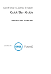
Installing the Fan Tray
The C-Series chassis contains one field-replaceable fan tray. There are two types
of fan trays that you can install: one contains six fans that run at varying speeds
depending on system temperature; the other contains six fans that run at a
constant speed. For both types of trays, air flows through the system toward the
fans (right to left) and is exhausted on fan-side of the chassis. The fan tray is
accessible from the front of the chassis.
WARNING: To ensure proper temperature and airflow control, the fan tray
must always be installed and operating properly.
NOTE: The system does not have an air filter. Ensure that you clean the
installation site and chassis regularly.
Step
Task
1
Slide the fan tray into the fan slot.
2
Gently push on the front of the tray until it stops. The fan tray should be
flush with the chassis.
3
Use a #2 Phillips screwdriver to secure the fan tray into place by
tightening the screws at the top and bottom of the fan tray.
Installing the Hardware
13
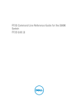
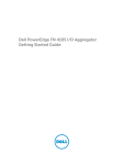
C7004/C150
0
1
R0
R1
2
3
C7008/C300
0
1
2
3
R0
R1
4
5
6
7
NOTE: The fan tray light emitting diodes (LEDs) remains lit when the chassis is
powered up and the fan tray is functioning properly.
Power Up Sequence
Before you supply power to the chassis, Dell Networking recommends reinspect your equipment rack and chassis.
CAUTION: Never operate the system without a fan tray.
14
Installing the Hardware
Step
Task
1
Verify that the power source complies with the system input power
requirements.
2
Energize the remote power source or outlet.
3
On the C7004/C150, toggle the switch on the AC power supplies to the
ON (right) position.
On the C7008/C300, toggle the switch on the AC power supplies to the
ON (top) position.
4
The power supply LEDs shows green. If these LEDs are not lit green:
• Check that the unit is properly installed.
• Verify the power source.
• If the power supply cannot be verified, power off all modules and
replace the unit.
5
The fan tray LED shows green (online). You can hear the air flowing
through the chassis. If the fans are not operating properly or air is not
flowing through the chassis:
• Power off all power supplies.
• Verify that the fan tray is properly installed.
• If the fan tray LED remains unlit, power down the unit, and replace the
fan tray.
After you supply power to the system, the following occurs:
•
The fan tray is operating.
•
The green (online) fan tray, RPM, and line card LEDs are lit and remain lit as
long as the system is receiving power and is operational.
When you supply power to the chassis, the system performs a series of power-on
self tests. RPM and line card LEDs blink as the diagnostic programs run. You do
not have to do anything while the tests run. Observe the process on your console
monitor. When the boot process completes, the card LEDs remain online (green)
and the console monitor displays the command line interface (CLI) prompt.
Installing the Hardware
15
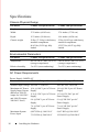
Specifications
Chassis Physical Design
Parameter
C7004/C150 Specifications
C7008/C300 Specifications
Height
15.7 inches (39.88 cm)
22.7 inches (57.66 cm)
Width
17.5 inches (44.45 cm)
17.4 inches (37.58 cm)
Depth
15.3 inches (38.86 cm)
14.4 inches (44.20 cm)
Chassis weight
38 lbs (17.24 kg) with factory
installed components
55 lbs (24.95 kg) with factory
installed components
86.63 lbs (39.29 kg) fully
loaded
152.27 lbs (69.07 kg) fully
loaded
Environmental Parameters
Parameter
C7004/C150 Specifications
C7008/C300 Specifications
Temperature
-40° to 158°F (-40°C to 70°C) -40° to 158°F (-40°C to 70°C)
(storage temperature)
(storage temperature)
Relative humidity
5 to 95% (non-condensing)
5 to 95% (non-condensing)
AC Power Requirements
Power Supply 1600W-AC
Parameter
C7004/C150 Specifications
Nominal input voltage 100-240 V 50/60 Hz
Maximum AC Power
Supply Input Current
(Based on 1200 W
output for 100/120 V
and 1600 W output
200/240 V lines)
Maximum System
Power Input
16
C7008/C300 Specifications
100-240 VAC 50/60 Hz
14 A @ 100 V per AC Power 14 A @ 100 V per AC Power
Supply
Supply
11 A @ 120 V per AC Power 11 A @ 120 VAC per AC
Supply
Power Supply
9 A @ 200 V per AC Power
Supply
9 A @ 200 VAC per AC
Power Supply
7 A @ 240 V per AC Power
Supply
7 A @ 240 VAC per AC
Power Supply
6,897 KVA @ 100/120 V
9,667 KVA @ 100/120 V
7,315 KVA @ 200/240 V
12,596 KVA @ 200/240 V
Installing the Hardware
Parameter
C7004/C150 Specifications
C7008/C300 Specifications
Maximum power
consumption
1,647 W @ 100/120 V
2,707 W @ 100/120 V
1,555 W @ 200/240 V
2,726 W @ 200/240 V
Maximum Thermal
Output at 100/120 V
5,618 BTU/hour
9,235 BTU/hour
Maximum Thermal
Output at 200/240 V
5,304 BTU/hour
9,299 BTU/hour
Power Supply 1200W-AC
Parameter
C7004/C150 Specifications
Nominal input voltage 100-240 V 50/60 Hz
Maximum AC Power
Supply Input Current
(Based on 1200 W
output for both
100/120 V and
200/240 V lines)
C7008/C300 Specifications
100-240 VAC 50/60 Hz
14 A @ 100 V per AC Power 14 A @ 100 V per AC Power
Supply
Supply
11 A @ 120 V per AC Power 11 A @ 120 VAC per AC
Supply
Power Supply
7 A @ 200 V per AC Power
Supply
7 A @ 200 VAC per AC
Power Supply
6 A @ 240 V per AC Power
Supply
6 A @ 240 VAC per AC
Power Supply
Maximum System
Power Input
4,261 KVA @ 100/120 V
8,274 KVA @ 100/120 V
4,165 KVA @ 200/240 V
8,088 KVA @ 200/240 V
Maximum power
consumption
1,304 W @ 100/120 V
2,361 W @ 100/120 V
1,208 W @ 200/240 V
2,175 W @ 200/240 V
Maximum Thermal
Output at 100/120 V
4,449 BTU/hour
8,055 BTU/hour
Maximum Thermal
Output at 200/240 V
4,122 BTU/hour
7,420 BTU/hour
Installing the Hardware
17
2
Installing the Software
Navigating CLI Modes
The Dell prompt changes to indicate the CLI mode. You must move linearly
through the command modes, with the exception of the end command which
takes you directly to EXEC Privilege mode; the exit command moves you up
one command mode level.
Console Access
The console port is an asynchronous serial port. If you connect a device to these
ports, it must be capable of asynchronous transmission.
Step
Task
1
Install an RJ-45 copper cable into the console port. Use a rollover cable to
connect the C7004/C150 or C7008/C300 console port to a terminal server.
2
Connect the other end of the cable to the DTE terminal server.
3
Set your terminal or terminal emulation mode to VT100 with the
following settings:
•
9600 baud rate (To avoid autobaud input, the default is set to a 9600
BPS.)
•
No parity
•
8 data bits
•
1 stop bit
•
Window Terminal Emulator option set to NO
•
24 lines X 80 characters
•
No flow control
Installing the Software
19
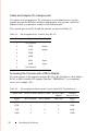
Cable and Adapter Pin Assignments
To connect to a terminal port, PC serial port, or a terminal server, use the
console port on the RPM to configure and monitor your system. An RJ-45
Ethernet cable is required to connect to the Ethernet port.
The console port is an RJ-45 and the pinouts are listed in Table 2-1.
Table 2-1. Pin Assignments for Console Port (RJ-45)
Pin
Signal
Input/Output
1
NC (unused
-
2
DTR
Output
3
TxD
Output
4
GND
-
5
GND
-
6
RxD
Input
7
DSR
Input
8
NC (unused
-
Accessing the Console with a DB-9 Adapter
You can connect to the console using an RJ-45 to RJ-45 rollover cable and an
RJ-45 to DB-9 female DTE adapter (labeled “TERMINAL”) to a terminal
server (for example, PC).
Table 2-2. Pin Assignments Between the Console and a DTE Terminal Server
Console Port
20
RJ-45 to RJ-45 Rollover Cable RJ-45 to DB-9
Terminal
Adapter
Server Device
Signal
RJ-45 Pinout
RJ-45 Pinout
DB-9 Pin
Signal
RTS
1
8
8
CTS
DTR
2
7
6
DSR
TxD
3
6
2
RxD
GND
4
5
5
GND
Installing the Software
Table 2-2.
Pin Assignments Between the Console and a DTE Terminal Server
Console Port
RJ-45 to RJ-45 Rollover Cable RJ-45 to DB-9
Terminal
Adapter
Server Device
Signal
RJ-45 Pinout
RJ-45 Pinout
DB-9 Pin
Signal
GND
5
4
5
GND
RxD
6
3
3
TxD
DSR
7
2
4
DTR
CTS
8
1
7
RTS
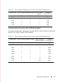
Accessing the Console with a DB-25 Adapter
You can connect to the console port using an RJ-45 to RJ-45 rollover cable and
an RJ-45 to a DB-25 female DTE adapter.
Table 2-3.
Pin Assignments Between the Console and a DTE Terminal Server
Console Port
RJ-45 to RJ-45 Rollover Cable
RJ-45 to DB-25
Modem Adapter
Terminal
Server Device
Signal
RJ-45 Pinout
RJ-45 Pinout
DB-25 Pinout
Signal
RTS
1
8
5
CTS
DTR
2
7
6
DSR
TxD
3
6
3
RxD
GND
4
5
7
GND
GND
5
4
7
GND
RxD
6
3
2
TxD
DSR
7
2
20
DTR
CTS
8
1
N/A
RTS
Installing the Software
21
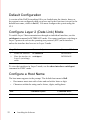
Default Configuration
A version of the Dell Networking OS is pre-loaded onto the chassis, however
the system is not configured when you power up for the first time (except for the
default host name, which is Dell). You must configure the system using the
CLI.
Configure Layer 2 (Data Link) Mode
To enable Layer 2 data transmissions through an individual interface, use the
switchport command in INTERFACE mode. You cannot configure switching or
Layer 2 protocols such as the spanning tree protocol (STP) on an interface
unless the interface has been set to Layer 2 mode.
Step Task
Command Syntax
Command Mode
1
Enable the interface.
no shutdown
INTERFACE
2
Place the interface in
Layer 2 (switching)
mode.
switchport
INTERFACE
To view the interfaces in Layer 2 mode, use the show interfaces switchport
command in EXEC mode.
Configure a Host Name
The host name appears in the prompt. The default host name is Dell.
•
Host names must start with a letter and end with a letter or digit.
•
Characters within the string can be letters, digits, and hyphens.
Task
Command Syntax
Command Mode
Create a new host name.
hostname name
CONFIGURATION
22
Installing the Software
Access the System Remotely
You can configure the system to access it remotely by Telnet.
The systems have a dedicated management port and a management routing table
that is separate from the IP routing table.
Configuring the system for Telnet is a three-step process:
Step
Task
1
Configure an IP address for the management port.
2
Configure a management route with a default gateway.
3
Configure a username and password.
Configure the Management Port IP Address
Assign IP addresses to the management ports.
NOTE: Assign different IP addresses to each RPM’s management port.
Step Task
Command Syntax
Command Mode
1
Enter INTERFACE
mode for the
Management port.
interface ManagementEthernet
slot/port
CONFIGURATION
2
Assign an IPv4 or
IPv6 address to the
interface.
ip address {ipv4-address | ipv6address}/mask
INTERFACE
3
Enable the interface.
no shutdown
INTERFACE
Configure a Management Route
Define a path from the system to the network from which you are accessing the
system remotely. Management routes are separate from IP routes and are only
used to manage the system through the management port.
Installing the Software
23
Task
Command Syntax
Command Mode
Configure an IPv4 or IPv6 management route {ipv4-address CONFIGURATION
management route to the | ipv6-address}/mask gateway
network from which you
are accessing the system.
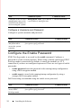
Configure a Username and Password
Configure a system username and password.
Task
Command Syntax
Configure a username username username password
and password to
[encryption-type] password
access the system
remotely.
Command Mode
CONFIGURATION
Configure the Enable Password
EXEC Privilege mode is accessed by the enable command. Configure a
password as a basic security measure. When using a console connection, EXEC
Privilege mode is unrestricted by default; it cannot be reached by a VTY
connection if you have not configured a password. There are two types of enable
passwords:
•
enable password stores the password in the running/startup configuration
using a DES encryption method.
•
enable secret is stored in the running/startup configuration by using a
stronger, MD5 encryption method.
Dell Networking recommends using the enable secret password.
Task
Command Syntax
Command Mode
Create a password to
access EXEC
Privilege mode.
enable [password | secret] [level level]
[encryption-type] password
CONFIGURATION
24
Installing the Software
Create a VLAN
The default virtual local area network (VLAN) is part of the system startup
configuration, and is by default, VLAN 1. You may make another VLAN the
default VLAN. You cannot delete, disable, or configure the default VLAN (you
cannot assign it an IP address), and only untagged interfaces can belong to it.
When you configure an interface, a switchport automatically places it in the
default VLAN as an untagged interface. All switchports must belong to at least
one VLAN, so to remove a switchport from the default VLAN, place it as
tagged or untagged in some other VLAN, or remove the switchport
configuration.
Task
Command Syntax
Command Mode
Create a VLAN.
interface vlan vlan-id
CONFIGURATION
Display all VLANs.
show vlan vlan-id
EXEC Privilege
Assign Interfaces to a VLAN
A port may either be an untagged member of a single VLAN, or a tagged
member of perhaps multiple VLANs.
•
Untagged Ports — ports that do not append an 802.1Q VLAN tag to frames
on egress, and do not accept tagged frames on ingress (tagged frames are
dropped). You must connect untagged ports to VLAN-unaware devices.
•
Tagged Ports — ports that append an 802.1Q tag to frames on egress, and
accept only tagged frames on ingress (untagged frames are dropped). You
must connect tagged ports to VLAN-aware devices.
When you configure an enabled port as a switchport, the port is placed in the
default VLAN. To remove a switchport from the default VLAN, remove the
switchport configuration. To move the port to another VLAN, add it to the
desired VLAN as either a tagged or untagged member.
To view just the interfaces that are in Layer 2 mode, enter the show interfaces
switchport command in EXEC mode.
Installing the Software
25
Step Task
Command Syntax
1
Assign a switchport to a
VLAN.
2
Display all switchports
show vlan
and the VLANs of which
they are members.
Command Mode
[tagged | untagged] interface INTERFACE VLAN
EXEC Privilege
Assign an IP address to a VLAN
NOTE: You cannot assign an IP address to the default VLAN, which, by default, is
VLAN 1. To assign another VLAN ID to the default VLAN, use the default vlan-id
vlan-id command.
Task
Command Syntax
Configure an IP address and mask on ip address ip-address
the interface.
mask [secondary]
Command Mode
INTERFACE
Connecting the Chassis to the Network
After you have completed the hardware installation and software configuration,
you can connect to your company network by following your company’s cabling
requirements.
26
Installing the Software
Printed in the U.S.A.
w w w. d e l l . c om | s u p p o r t . d e l l . c om