1
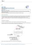
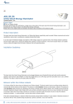
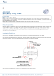
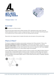
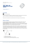
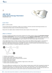
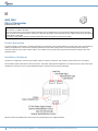
AEO_MEI
Micro Illuminator
Firmware Version : 1.24
Quick Start
A This device is a Z-Wave Actuator.
Single click the button located near the Status Indication LED or alternatively press the external switch/ button control quickly 6
times to include or exclude the device. If the Aeon Labs Micro Illuminator is not included into any Z-Wave network, the LED will be
blinking slowly continually.
Please refer to the chapters below for detailed information about all aspects of the products usage.
Product description
The Aeon Labs Micro Illuminator is a Z-Wave light dimmer specifically used to enable Z-Wave command and control (on/off/dim) for
existing in-wall dimmers. The wireless module is powered from the mains supply and is a three-wire design which requires a
neutral connection. In the event of power failure, non-volatile memory retains all programmed information relating to the units
operating status.
Installation Guidelines
The device is designed for a 3 wire system which requires a neutral connection. The module is powered from the main supply.
The schematic below shows how to wire the actuator. The power supply and the appliance are connected by the Load, Power Input
and Neutral connectors. The 3.3 Volt and External Switch connectors are for external switching.
After the electrical installation the device has to be implemented in the Z-Wave Network.
1
(c) 2012 Z-Wave Europe GmbH, Goldbachstr. 13, 09337 Hohenstein-Ernstthal, Germany, www.zwaveeurope.com
Behavior within the Z-Wave network
I On factory default the device does not belong to any Z-Wave network. The device needs to join an existing wireless network to
communicate with the devices of this network. This process is called Inclusion. Devices can also leave a network. This process is
called Exclusion. Both processes are initiated by the primary controller of the Z-Wave network. This controller will be turned into
exclusion respective inclusion mode. Please refer to your primary controllers manual on how to turn your controller into inclusion
or exclusion mode. Only if the primary controller is in inclusion or exclusion mode, this device can join or leave the network.
Leaving the network - i.e. being excluded - sets the device back to factory default.
If the device already belongs to a network, follow the exclusion process before including it in your network. Otherwise inclusion of
this device will fail. If the controller being included was a primary controller, it has to be reset first.
To include the Aeon Labs Micro Illuminator with your Z-Wave controller simple bring it in the inclusion-mode and click the
Inclusion/Exclusion button at the Aeon Labs Micro Illuminator once. Alternatively you can use the external switch by quickly
pressing it six times. If the Aeon Labs Micro Illuminator was successfully included to a Z-Wave network, the Status Indication LED
will either be solid on or off (depending on if the switch is on or off) 10 seconds after the button was last pressed.
Operating the device
The dimmer is operated by an external switch/button or wireless. The click on the switch sets the dimmer on or off. To have the
dimming function simple hold the button pushed until your desired level. The dimmer insert memorizes the last lighting level and
switches automatically to the same level.
Node Information Frame
NIF The Node Information Frame is the business card of a Z-Wave device. It contains information about the device type and the
technical capabilities. The inclusion and exclusion of the device is confirmed by sending out a Node Information Frame. Beside this
it may be needed for certain network operations to send out a Node Information Frame.
A single click at the Inclusion/Exclusion switch sends a Node Information Frame.
LED Control
●
●
The LED on the Micro Illuminator will blink if it is currently not paired into a Z-Wave network.
If the Aeon Labs Micro Illuminator was successfully included to a Z-Wave network, the Status Indication LED will either be solid on
or off (depending on if the switch is on or off) 10 seconds after the button was pressed.
Associations
A Z-Wave devices control other Z-Wave devices. The relationship between one device controlling another device is called
association. In order to control a different device, the controlling device needs to maintain a list of devices that will receive
controlling commands. These lists are called association groups and they are always related to certain events (e.g. button
pressed, sensor triggers, ...). In case the event happens all devices stored in the respective association group will receive a
common wireless command.
Association Groups:
1
Status Reports (max. nodes in group: 5)
Configuration Parameters
Z-Wave products are supposed to work out of the box after inclusion, however certain configuration can adapt the function better
to user needs or unlock further enhanced features.
IMPORTANT: Controllers may only allow configuring signed values. In order to set values in the range 128 … 255 the value sent in
2
(c) 2012 Z-Wave Europe GmbH, Goldbachstr. 13, 09337 Hohenstein-Ernstthal, Germany, www.zwaveeurope.com
the application shall be the desired value minus 256. For example: to set a parameter to 200 it may be needed to set a value of
200 minus 256 = minus 56. In case of a two byte value the same logic applies: Values greater than 32768 may needed to be given
as negative values too.
Type of Sensor Report (Parameter Number 1, Parameter Size 1) Defines the value type to be sent as Sensor
Report.
Value
Description
0
Power (Default)
1
Voltage
Blinking Behavior (Parameter Number 2, Parameter Size 2) This is a double byte value. The LSB defines the total
time the device need to blink. The value if set in seconds. The MSB defines the on/off interval of the blinking. The unit is 0.1 s.
Value
Description
0 — 65535
Configuration Bytes (Default 0)
Notification on Status Change (Parameter Number 80, Parameter Size 1) Defines the automated status
notification of an associated device when status changes
Value
Description
0
Deactivated (Default)
1
Hail sent
2
BASIC Report Sent
Disables Function of automated sending of a Report triggered by minimal change of value.
(Parameter Number 90, Parameter Size 1)
Value
Description
0
Disabled (Default)
1
Enabled
Minimum Change to send Report (Watt) (Parameter Number 91, Parameter Size 2) The value represents
the minimum change in Wattage for a Report to be sent .
Value
Description
0 — 32000
W (Default 50)
Minimum Change to send Report (%) (Parameter Number 92, Parameter Size 1) The value represents the
minimum change in Watage Percent for a report to be sent
Value
Description
0 — 255
% (Default 10)
Report type send in Reporting Group 1 (Parameter Number 101, Parameter Size 4) Defines the type of
report sent for the Reporting Group 1.
3
(c) 2012 Z-Wave Europe GmbH, Goldbachstr. 13, 09337 Hohenstein-Ernstthal, Germany, www.zwaveeurope.com
Value
Description
2
MultiSensor Report
4
Meter Report for Watt
8
Meter Report for kWh (Default)
Report Type send in Reporting Group 2 (Parameter Number 102, Parameter Size 4) Defines the type of
report sent for the Reporting Group 2.
Value
Description
2
MultiSensor Report
4
Meter Report for Watt
8
Meter Report for kWh
Report Type send in Reporting Group 3 (Parameter Number 103, Parameter Size 4) Defines the type of
report sent for the Reporting Group 3.
Value
Description
2
MultiSensor Report
4
Meter Report for Watt
8
Meter Report for kWh
Send Interval for Reporting Group 1 (Parameter Number 111, Parameter Size 4) Defines the time interval
when the defined report of Reporting Group 1 is sent out.
Value
Description
0 — 65535
Interval (Default 720)
Send Interval for Reporting Group 2 (Parameter Number 112, Parameter Size 4) Defines the time interval
when the defined report of Reporting Group 2 is sent out.
Value
Description
0 — 65535
Interval (Default 720)
Send Interval for Reporting Group 3 (Parameter Number 113, Parameter Size 4) Defines the time interval
when the defined report of Reporting Group 3 is sent out.
Value
Description
0 — 32000
Interval
Technical Data
Explorer Frame Support
4
No
(c) 2012 Z-Wave Europe GmbH, Goldbachstr. 13, 09337 Hohenstein-Ernstthal, Germany, www.zwaveeurope.com
SDK
5.02 pl3
Device Type
Slave with routing capabilities
Generic Device Class
Multilevel Switch
Specific Device Class
Multilevel Power Switch
Routing
Yes
FLiRS
No
Firmware Version
1.24
5
(c) 2012 Z-Wave Europe GmbH, Goldbachstr. 13, 09337 Hohenstein-Ernstthal, Germany, www.zwaveeurope.com