1
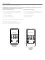
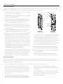
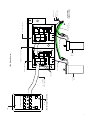
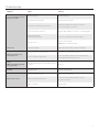
INSTRUCTION BOOK FOR
Tensioned Horizon Electrol®
Important Safety Instructions
When using your video equipment, basic safety precautions should always be followed, including the following:
1. Read and understand all instructions before using.
4. To reduce the risk of electric shock, do not disassemble this
appliance. Contact an authorized service dealer when repair
work is required. Incorrect reassembly can cause electric shock
when the appliance is used subsequently.
2. Position the cord so that it will not be tripped over, pulled, or
contact hot surfaces.
3. If an extension cord is necessary, a cord with a current rating at
least equal to that of the appliance should be used. Cords rated
for less amperage than the appliance may overheat.
5. The use of an accessory attachment not recommended by the
manufacturer may cause a risk of fire, electric shock, or injury to
persons.
Save These Instructions
Pre-Installation
1. Carefully unpack screen and remove outer wrapping from
case.
2. Make sure to recheck measurements of screen location
before installation.
Junction Box
Mask
Motor
Mask Surface
Drywall Screw
Access Panel
Machine Screw
Truss Head Screw
Splitter
Junction
Box
Shipping Bracket
Hex Head Screw
Installation
Screen
Motor
Slats
Figure 1
Tape Strips
Picture Surface
Figure 2
1. Install screen by raising unit into position between joists at one
end only. Install one lag screw in each mounting bracket.
CAUTION! Do not cut tape on fabric with knife or any sharp
tool. Pull orange string.
2. Level unit lengthwise with a carpenter’s level and plumb level.
Secure opposite end.
ATTENTION! Ne coupez pas le ruban adhésif sur la toile avec
un couteau ou un outil tranchant. Tirez sur le cordon orange.
3. Detach access panel by removing screws (Figure 1).
10. Use supplied 1/8” nex key and a 5/16” wrench to remove silver
shipping brackets attached to slat and screen case.
CAUTION! Do not seal in until screen has been secured in
position and properly tested for satisfactory operation.
ATTENTION! Ne fixez pas l'écran jusqu'à ce qu'il ait été
correctement mis en place et qu'il fonctionne
convenablement.
4. Remove the two screws holding the splitter junction box (Figure 2).
5. Unwrap the supplied 25 ft. RJ-14 cord. Plug one end into a QEYE
port on the primary splitter (see wiring diagram).
6. Run the 25 ft. RJ-14 card to the back of the wall keypad and
plug into the RJ receptacle.
7. Remove the two screws holding the junction box cover plate.
Install the electrical hookup (see wiring diagram).
NOTE: Must be installed in accordance with the requirements
of the Local Building Codes, the Canadian Electrical Code (CEC),
CAN/CSA C22.1 and the National Electric Code (NEC), NFPA 70.
8. After the electrical connections are completed, replace the
junction box cover plate.
9. Carefully remove tape strips securing picture surface around roller.
11. Carefully remove wood boards securing mask surface to case.
12. Test installation by carefully running picture surface and mask
surfaces up and down several times. Be prepared to stop the
screen. IMPORTANT: Read operating instructions before
testing screen.
NOTE: When rolled down, the picture surface should wrap
fully around the roller. No part of the roller should be exposed.
Picture surface and mask surfaces will automatically stop in
the down position.
CAUTION! Excessive continuous operation may cause
overheating. If this happens, the motors will shut off until they
cool to a normal operating temperature. Duty Cycle of screen
is 1 Min. on / 3 Min. off.
ATTENTION! Le fonctionnement continu et excessif peut
provoquer une surchauffe.Si cela se produit, les moteurs
s'arrêteront jusqu'à qu'ils se soient refroidis à la température
normale de fonctionnement. Le cycle de fonctionnement est
de 1 min. en marche / 3 min. à l'arrêt.
Screen Operation
The Horizon has been preset to three or four different formats. The screen can be set to any format by pressing the corresponding
button on the keypad. Below is a list of each button function.
IMPORTANT! When operating the switch, press and release buttons. Do not hold the button for more than three (3) seconds or
the button will be reprogrammed to the current screen position.
Native NTSC (1.33:1) Format Screens
Native HDTV (1.78:1) Format Screens
1. Lowers screen to NTSC (1.33:1) format. Mast will travel down and
reverse wrap on the roller. The mask it not used for this format.
1. Lowers screen to HDTV (1.78:1) format. Mast will travel down and
reverse wrap on the roller. The mask it not used for this format.
2. Sets format to HDTV (1.78:1).
2. Sets format to Letterbox (1.85:1).
3. Sets format to Letterbox (1.85:1).
3. Sets format to Cinemascope (2.35:1).
4. Sets format to Cinemascope (2.35:1).
4. Open: User defined preset.
Stop - Stops the screen and mask movement at any position when pressed.
Up - Returns the screen and mask to the up position.
Screen - Runs the screen up and down without mask movement.
Mask - Runs the mask up and down without screen movement.
Format Selection
1
2
Format Selection
3
4
1
Screen
2
3
4
Mask
Screen
Mask
Up
Stop
Up
Stop
Wall Keypad
Transmitter
Dual IR/RF
Remote
3
Screen Adjustment
Motor Limit Adjustments
Surface travel is stopped automatically in the fully opened and closed positions by limit switches that are properly adjusted at Da-Lite.
Should it be necessary to adjust for more or less drop of picture, proceed in the following manner:
LED
1. Remove the two screws holding the junction box cover. Located
on the left end of the case (see Figure 1).
Up
Limit
Tactile
Button
2. Unplug the 6P6C wire that is plugged into the secondary splitter
"QEYE" port (see wiring diagram).
3. Unplug the 6P4C wire from the Operating Keypad at the wall.
Plug the 6P4C wire into the Limit Setting Switch. The LED on the
back of the Limit Setting Switch will blink green twice.
4. If adjusting the screen limit, the 6P4C cable will need to be
plugged into the "QEYE" port of the primary splitter. If adjusting
the mask limit it will need to be plugged into a "QEYE" port on the
secondary splitter.
5. Press and hold both the Up and Down Limit Switch on the back
of the Limit Setting Switch until the LED blinks red twice.
6. To adjust the down limit, press and hold the Down tactile button
until the LED on the back of the Limit Setting Switch turns solid
red. This will put the motor in limit set mode. Turn the switch over
and use the Down button on front of switch. Press and hold until
the desired travel position is reached. If you travel too far down,
press the UP button to move the screen upward. If you press and
let go of either the UP or DOWN button, the motor will do a small
jog in that direction for finer adjustment of the screen. Once the
desired position is reached, turn the switch over and press and
hold the DOWN tactile button until the LED on the back of the
switch blinks red twice. The down limit is now set.
7. To adjust the up limit, press and hold the UP tactile button until
the LED on the back of the Limit Setting Switch turns solid green.
This will put the motor in limit set mode. Turn the switch over and
use the UP button on front of switch. Press and hold until the
desired travel position is reached. If you travel too far up, press
UP
STO
P
DO
WN
Down
Limit
Tactile
Button
Front of
Wall Switch
Back of
Wall Switch
the DOWN button to move the screen downward. If you press
and let go of either the UP or DOWN button, the motor will do a
small jog in that direction for finer adjustment of the screen.
Once the desired position is reached, turn the switch over and
press and hold the UP tactile button until the LED on the back of
the switch blinks green twice. The down limit is now set.
8. To test limit switch settings, press and release the UP or DOWN
button on the Limit Setting Switch to operate the screen.
9. Press and hold both the UP and DOWN tactile buttons on the
back of the Limit Setting Switch until the LED blinks red twice.
10. Unplug the 6P4C cable from the limit switch and plug it back into
the Operating Keypad.
11. Plug the 6P6C connector back into the "QEYE" port of the
secondary splitter and replace the splitter junction box cover.
Intermediate Positions.
The motors on the Horizon Electrol® have been preset to three or four different screen formats based on your screen size. See the
Screen Operation section for the standard screen formats. It is possible to adjust these format for your particular needs. The following
instructions will walk you through this process.
(See Motor Limit Adjustments to adjust the stop positions for all the way up or all the way down positions)
1. Press the screen down button on the wall keypad or remote.
When the screen reached the desired position, press the stop
button. If you go past the desired position, press the stop button
and then press the up arrow to return the screen to a position
above the new stop point and try again until the screen stops at
the new position.
2. Press the mask down button on the wall keypad or remote.
When the mask reached the desired level, press the stop button.
If you go pas the desired position, press the stop button and
4
then press the up arrow to return the mask to a position
above the new stop point and try again until the mask stops at
the new position.
3. Press and hold either the 1, 2, 3 or 4 button until the LED stop
blinking. The new stop position is now recorded for the selected
button. Repeat this process for any other changes to the
remaining three positions.
IR Eye
Stop
Mask
Wall Keypad Transmitter
Up
Screen
Format Selection
1
2
3
4
Inputs
QEYE
Data Cable
Mask
Motor
Data Cable
QEYE
Screen
Motor
25 FT. 6P4C
Wire Supplied
Primary Splitter
6P6C Connector Wire
120V Wiring Diagram
Secondary Splitter
QAUX
LED
QAUX
QEYE
QEYE
Green
(Ground)
QEYE
QEYE
5
Power Input
120VAC / 60Hz
White
(Common)
Black (Hot)
Suggested Methods Of Installation
Select Installation Method According To Ceiling Type.
NOTE: Must mark hole location of screws in 3-1/2" panel for removal, if covering with tile.
9"
8 11/16"
Case Length = Screen Fabric Width
+ 15 3/4", All Sizes
7 7/8"
1 1/2"
Mounting Bracket
Electrical Outlet
On This End Of Case
Motor End
Control Wire Outlet
7 7/8"
METHOD B
METHOD A
(Suggested)
1/4" Lag Screws
9 1/4"
9"
Mounting
Bracket
9 1/4"
9"
(Suggested)
1/4" Lag Screws
Mounting
Bracket
1 1/2"
1 1/2"
1 1/2"
1 1/2"
8 11/16"
Furring
Strip
Mounting Joist
8 13/16"
Mounting Joist
8 15/16"
Furring
Strip
3/4" Finished
Ceiling
3/4" Finished
3 1/2"
Ceiling
Panel
Can Be Painted Same As Ceiling
or Removed And Replaced With
Finished Ceiling
Aluminum Slat
Picture Surface
Masking Surface
1/4" x 1" Alum Bar In Pocket
Offset mounting, recessed above ceiling. For plaster, dry wall,
tile or paneling. Bottom of case painted same finish as ceiling.
3 1/2"
Panel
9 1/16"
Picture Surface
Masking Surface
Ceiling Tile Cut To 1/4" Thick
(Attach With Mastic)
Aluminum Slat
1/4" x 1" Alum Bar In Pocket
Offset mounting, recessed above ceiling. May be adapted for
3/4" ceiling, but cut to 1/4" thick under screen case and panel.
METHOD D
METHOD C
(Suggested)
1/4" Lag Screws
Mounting
Bracket
9 3/16"
9"
1 1/2"
9 1/16"
Mounting Joist
8 15/16"
Furring
Strip
3 1/2"
Panel
Aluminum Slat
Picture Surface
Masking Surface
3/16" x 1" Alum. Bar In Pocket
Offset mounting, recessed above ceiling. May be adapted for
1/4" paneling for ceiling.
6
(Suggested)
1/4"
1 1/2"
Bolts
Mounting
Joist
1 1/2"
Finished
Ceiling
1 1/2"
9 1/16"
Furring
Strip
Suspended
Ceiling Tile
T-Bar Furnished
With Ceiling
3 1/2"
Panel
Aluminum Slat
8 15/16"
Picture Surface
Masking Surface
1/4" x 1" Alum Bar In Pocket
Flush mounting, recessed above ceiling. For use with dropped
ceiling. May also be adapted for use with acoustical or other
ceiling 3/4" thick but cut to 1/4" thick under screen case and panel.
Troubleshooting
Symptom
Cause
Solution
Screen or mask will not operate.
Motor does not hum.
Blown facility fuse.
Replace facility fuse.
Tripped facility circuit breaker.
Reset facility circuit breaker.
No power to control board in junction box.
Check above. Tighten all loose wire connections.
Correct any improper connections.
Loose control wire connections.
Check all T4 and T6 wire connections – see wiring diagram.
Power at junction box
Thermal overload tripped.
Let motor cool down for 15 minutes. Try again.
Defective motor.
Replace motor assembly.
NOTE: Motor is a sealed assembly.
Temporary binding.
With power off, turn roller by hand to free binding.
Screen not set to the correct format.
Set screen to the format being projected.
Screen or mask out of adjustment.
See screen adjustment. We recommend you have your
dealer make these adjustments for you.
Noise.
NOTE: Screen will operate with
a low pitched hum.
Grinding. Foreign object in screen rubbing on roller
or fabric.
Remove.
Coasting.
Defective brake.
Replace motor assembly.
Screen not installed properly.
Check for level and plumb.
Fabric has backed up inside case.
Lower screen and carefully pull fabric to remove
any slack on the roller.
Fabric is damaged.
Replace fabric.
Motor hums.
Image on screen does not
match picture area.
Fabric hangs crooked.
7
LIMITED ONE YEAR WARRANTY ON DA-LITE PRESENTATION PRODUCTS
Milestone AV Technologies LLC warrants certain Da-Lite branded products to the original purchaser only, to be free from defects in
materials and workmanship for a period of one (1) year from the date of purchase by the original purchaser; provided they are properly
operated according to Da-Lite's instructions and are not damaged due to improper handling or treatment after shipment from the
factory.
This warranty does not apply to equipment showing evidence of misuse, abuse or accidental damage, or which has been tampered
with or repaired by a person other than authorized Da‑Lite personnel.
Da-Lite’s sole obligation under this warranty shall be to repair or to replace (at Da-Lite’s option) the defective part of the merchandise.
Returns for service should be made to your Da-Lite dealer. If it is necessary for the dealer to return the screen or part to Da-Lite,
transportation expenses to and from Da-Lite are payable by the purchaser and Da-Lite is not responsible for damage in shipment.
To protect yourself against damage or loss in transit, insure the product and prepay all transportation expenses.
TO THE MAXIMUM EXTENT PERMITTED BY APPLICABLE LAW, THIS WARRANTY IS IN LIEU OF ALL OTHER WARRANTIES, EXPRESS
OR IMPLIED, INCLUDING WARRANTIES AS TO FITNESS FOR USE AND MERCHANTABILITY. Any implied warranties of fitness for use,
or merchantability, that may be mandated by statute or rule of law are limited to the one (1) year warranty period. This warranty gives
you specific legal rights, and you may also have other rights, which vary from state-to-state. TO THE MAXIMUM EXTENT PERMITTED
BY APPLICABLE LAW, NO LIABILITY IS ASSUMED FOR EXPENSES OR DAMAGES RESULTING FROM INTERRUPTION IN OPERATION
OF EQUIPMENT, OR FOR INCIDENTAL, DIRECT, OR CONSEQUENTIAL DAMAGES OF ANY NATURE.
In the event that there is a defect in materials or workmanship of a Da-Lite product, you may contact our Sales Partners at PO Box 137,
Warsaw, IN 46581-0137, (574) 267-8101, (800) 622-3737.
IMPORTANT: THIS WARRANTY SHALL NOT BE VALID AND DA-LITE BRANDED PRODUCTS SHALL NOT BE BOUND BY THIS
WARRANTY IF THE PRODUCT IS NOT OPERATED IN ACCORDANCE WITH THE DA-LITE WRITTEN INSTRUCTIONS.
Keep your sales receipt to prove the date of purchase and your original ownership.
A Milestone AV Technologies Brand
3100 North Detroit Street
Warsaw, Indiana 46582
P: 574.267.8101 or 800.622.3737
F: 574.267.7804 or 877.325.4832
E: [email protected]
www.da-lite.com
DL–0276 (Rev. 2) 10.14
© 2014 Milestone AV Technologies LLC. Printed in U.S.A.
83503