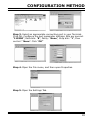
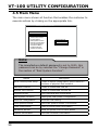
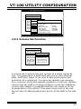
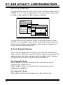
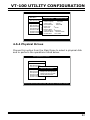
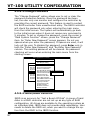
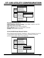
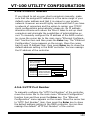
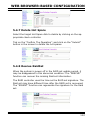
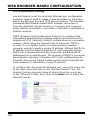
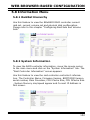
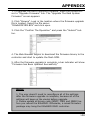
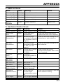
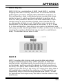
1
ELITERAID ER208UT+B
DETAILED USER’S MANUAL v1.0
WARRANTY
The information in this document is subject to change without notice.
We make no warranty of any kind regarding this material, including, but
not limited to, the implied warranties or merchantability and fitness for
a particular purpose. Furthermore, we shall not be liable for errors contained herein or for incidental or consequential damage in connection
with the furnishing, performance, or use of this material.
FCC STATEMENT
This equipment has been tested and found to comply with the limits for
a Class B digital device, pursuant to part 15 of the FCC Rules. These
limits are designed to provide reasonable protection against interference in a residential installation. This equipment generates, uses, and
can radiate radio frequency energy and, if not installed and used in accordance with the instructions, may cause harmful interference to radio
communications. However, there is no guarantee that interference will
not occur in a particular installation.
CE Mark
This equipment is in conformity with EM directive.
Contents
1. Introduction............................................................... 10
1.1 System Architecture.......................................................... 10
1.1.1 eSATA/USB 2.0 Host Interface . ..................................... 10
1.1.2 SATA ll Drive Interface ................................................ 11
1.2 RAID Controller Controller Board ........................................ 11
1.2.1 Unparalleled Performance.............................................. 11
1.2.2 Unsurpassed Data Availability........................................ 12
1.2.3 Easy RAID Management................................................ 12
2. Configuration Methods............................................... 14
2.1 Using local rear panel touch-control keypad..........................14
2.2 VT100 terminal (Using the controller’s serial port).................16
2.2.1 RAID Controller RS-232C Port Pin Assignment..................16
2.2.2 Start-up VT100 Screen..................................................17
2.3 Web browser-based RAID manager......................................20
2.4 Configuration Menu Tree....................................................20
3. LCD Configuration Menu.............................................22
3.1 Starting LCD Configuration Utility.......................................22
3.2 LCD Configuration Utility Main Menu Options.........................23
3.3 Configuring Raid Sets and Volume Sets................................24
3.4 Designating Drives as Hot Spares........................................24
3.5 Using Easy RAID Configuration ..........................................24
3.6 Using Raid Set and Volume Set Functions ............................26
3.7 Navigation Map of the LCD ................................................27
3.7.1 One-step creation Using LCD Hot Key..............................29
3.7.2 Quick Volume And Raid Setup........................................29
3.7.3 Raid Set Functions........................................................30
3.7.3.1 Create A New Raid Set ............................................31
3.7.3.2 Delete Raid Set.......................................................31
3.7.3.3 Expand Raid Set......................................................32
3.7.3.4 Offline RAID Set......................................................32
3.7.3.5 Activate Incomplete RaidSet......................................33
3.7.3.6 Create Hot Spare Disk..............................................33
3.7.3.7 Delete Hot Spare Disk..............................................33
3.7.3.8 Display Raid Set Information.....................................33
3.7.4 Volume Set Functions...................................................34
3.7.4.1 Create Raid Volume Set ...........................................35
3.7.4.1.1 Volume Name......................................................35
3.7.4.1.2 Raid Level .........................................................35
3.7.4.1.3 Stripe Size..........................................................35
3.7.4.1.4 Cache Mode........................................................36
3.7.4.1.5 Host Channel......................................................36
3.7.4.1.6 Drive Number......................................................36
3.7.4.1.7 SATA Xfer Mode...................................................37
3.7.4.1.8 Capacity.............................................................37
3.7.4.1.9 Initialization Mode................................................37
3.7.4.2 Delete Existed Volume Set........................................38
3.7.4.3 Modify Volume Set Attribute......................................38
3.7.3.3.1 Volume Set Migration...........................................39
3.7.4.4 Check Volume Set Consistency..................................39
3.7.4.5 Stop Volume Set Consistency Check...........................39
3.7.4.6 Display Volume Set Information.................................39
3.7.5 Physical Drive Functions ...............................................40
3.7.5.1 Display Drive Information ........................................41
3.7.5.2 Create Pass Through Disk ........................................41
3.7.5.3 Modify Pass Through Disk ........................................42
3.7.5.4 Delete Pass Through Disk.........................................42
3.7.5.5 Identify The Selected Drive.......................................42
3.7.6 Raid System Functions..................................................42
3.7.6.1 Mute The Alert Beeper . ...........................................45
3.7.6.2 Alert Beeper Setting . ..............................................45
3.7.6.3 Change Password....................................................45
3.7.6.4 JBOD/RAID Mode Configuration.................................45
3.7.6.5 Raid Rebuild Priority.................................................46
3.7.6.6 Maximum SATA Mode Supported................................46
3.7.6.7 Host NCQ Mode Setting............................................46
3.7.6.8 HDD Read Ahead Cache............................................47
3.7.6.9 Volume Data Read Ahead..........................................47
3.7.6.10 Stagger Power On Control.......................................47
3.7.6.11 Spin Down Idle HDD...............................................48
3.7.6.12 Empty HDD Slot LED Control...................................48
3.7.6.13 HDD SMART Status Polling......................................48
3.7.6.14 Disk Capacity Truncation Mode................................48
3.7.6.15 Terminal Port Configuration.....................................49
3.7.6.16 Shutdown The Controller........................................50
3.7.6.17 Restart The Controller............................................50
3.7.7 Ethernet Configuration..................................................50
3.7.7.1 DHCP.....................................................................50
3.7.7.2 Local IP Adress........................................................51
3.7.7.3 HTTP Port Number...................................................51
3.7.7.4 Telnet Port Number..................................................51
3.7.7.5 SMTP Port Number...................................................52
3.7.7.6 Ethernet Address.....................................................52
3.7.8 Show System Events....................................................52
3.7.9 Clear all Event Buffers...................................................52
3.7.10 Hardware Monitor Information......................................52
3.7.11 System Information....................................................53
4. VT-100 Utility Configuration ......................................54
4.1 Configuring Raid Sets/Volume Sets......................................54
4.2 Designating Drives as Hot Spares........................................55
4.3 Using Quick Volume /Raid Setup Configuration......................55
4.4 Using Raid Set/Volume Set Function Method.........................57
4.5 Main Menu ......................................................................59
4.5.1 Quick Volume/Raid Setup..............................................60
4.5.2 Raid Set Function.........................................................63
4.5.2.1 Create Raid Set ......................................................64
4.5.2.2 Delete Raid Set.......................................................65
4.5.2.3 Expand Raid Set......................................................66
4.5.2.4 Offline Raid Set.......................................................67
4.5.2.5 Activate Raid Set.....................................................67
4.5.2.6 Create Hot Spare.....................................................68
4.5.2.7 Delete Hot Spare.....................................................68
4.5.2.8 Rescue Raid Set......................................................69
4.5.2.9 Raid Set Information................................................69
4.5.3 Volume Set Function.....................................................70
4.5.3.1 Create Volume Set...................................................71
4.5.3.1.1 Volume Name......................................................72
4.5.3.1.2 Raid Level...........................................................73
4.5.3.1.3 Capacity.............................................................73
4.5.3.1.4 Strip Size............................................................75
4.5.3.1.5 Host Channel......................................................75
4.5.3.1.6 Drive Number......................................................76
4.5.3.1.7 Cache Mode........................................................77
4.5.3.1.8 SATA Xfer Mode...................................................77
4.5.3.2 Delete Volume Set...................................................78
4.5.3.3 Modify Volume Set...................................................79
4.5.3.3.1 Volume Expansion................................................79
4.5.3.3.2 Volume Set Migration...........................................80
4.5.3.4 Check Volume Set....................................................81
4.5.3.5 Stop Volume Set Check............................................81
4.5.4 Physical Drives.............................................................82
4.5.4.1 View Drive Information . ..........................................83
4.5.4.2 Create Pass-Through Disk.........................................83
4.5.4.3 Modify Pass-Through Disk.........................................84
4.5.4.4 Delete Pass-Through Disk.........................................84
4.5.4.5 Identify Selected Drive.............................................84
4.5.5 Raid System Function...................................................85
4.5.5.1 Mute The Alert Beeper . ...........................................85
4.5.5.2 Alert Beeper Setting.................................................86
4.5.5.3 Change Password....................................................87
4.5.5.4 JBOD/RAID Function................................................87
4.5.5.5 Background Task Priority..........................................88
4.5.5.6 Maximum SATA Mode...............................................89
4.5.5.7 Host NCQ Mode Setting............................................89
4.5.5.8 HDD Read Ahead Cache............................................90
4.5.5.9 Volume Data Read Ahead..........................................91
4.5.5.10 Stagger Power On..................................................91
4.5.5.11 Spin Down Idle HDD...............................................92
4.5.5.12 Empty HDD Slot LED..............................................93
4.5.5.13 HDD SMART Status Polling......................................94
4.5.5.14 Auto Activate Raid Set............................................94
4.5.5.15 Capacity Truncation . .............................................95
4.5.5.16 Terminal Port Config...............................................96
4.5.5.17 Update Firmware...................................................97
4.5.5.18 Shutdown Controller...............................................97
4.5.5.19 Restart Controller..................................................97
4.5.6 Ethernet Configuration .................................................98
4.5.6.1 DHCP Function........................................................99
4.5.6.2 Local IP Address.................................................... 100
4.5.6.3 HTTP Port Number................................................. 100
4.5.6.4 Telent Port Number................................................ 101
4.5.6.5 SMTP Port Number................................................. 102
4.5.6.6 Ethernet Address................................................... 102
4.5.7 View System Events................................................... 103
4.5.8 Clear Events Buffer..................................................... 104
4.5.9 Hardware Monitor Information..................................... 104
4.5.10 System Information.................................................. 105
5. Web Browser-based Configuration .......................... 106
5.1 Firmware-embedded TCP/IP & web browser-based RAID manager (using the controller’s 10/100 LAN port)........................... 107
5.2 Web Browser Start-up Screen .......................................... 107
5.2.1 Main Menu ............................................................... 108
5.3 Quick Function................................................................ 108
5.3.1 Quick Create . ........................................................... 108
5.4 RaidSet Functions........................................................... 109
5.4.1 Create Raid Set ......................................................... 109
5.4.2 Delete Raid Set.......................................................... 110
5.4.3 Expand Raid Set......................................................... 110
5.4.4 Offline Raid Set.......................................................... 111
5.4.5 Activate Raid Set........................................................ 111
5.4.6 Create Hot Spare....................................................... 111
5.4.7 Delete Hot Spare........................................................ 112
5.4.8 Rescue RaidSet ........................................................ 112
5.5 VolumeSet Functions....................................................... 113
5.5.1 Create Volume Set .................................................... 113
5.5.2 Delete Volume Set...................................................... 116
5.5.3 Modify Volume Set...................................................... 117
5.5.3.1 Volume Expansion................................................. 117
5.5.3.2 Volume Set Migration............................................. 117
5.5.4 Check Volume Set...................................................... 118
5.5.5 Stop Volume Set Check............................................... 118
5.6 Physical Drive ................................................................ 118
5.6.1 Create Pass Through .................................................. 118
5.6.2 Modify Pass Through................................................... 119
5.6.3 Delete Pass Through Disk............................................ 119
5.6.4 Identify Drive............................................................ 120
5.7 System Controls............................................................. 120
5.7.1 System Configuration.................................................. 120
5.7.2 EtherNet Config ........................................................ 125
5.7.3 Alert By Mail Config ................................................... 126
5.7.4 SNMP Configuration ................................................... 127
• SNMP Trap Configurations............................................... 127
• SNMP System Configurations........................................... 127
• SNMP Trap Notification Configurations............................... 127
5.7.5 NTP Configuration (Ethernet Port Support)..................... 128
5.7.6 View Events/Mute Beeper............................................ 129
5.7.7 Generate Test Event................................................... 130
5.7.8 Clear Events Buffer..................................................... 130
5.7.9 Modify Password........................................................ 130
5.7.10 Upgrade Firmware.................................................... 131
5.7.11 Shutdown Controller................................................. 131
5.7.12 Restart Controller .................................................... 131
5.8 Information Menu........................................................... 132
5.8.1 RaidSet Hierarchy....................................................... 132
5.8.2 System Information.................................................... 132
5.8.3 Hardware Monitor....................................................... 133
Appendix A................................................................... 134
Upgrading Flash Firmware Programming Utility......................... 134
Establishing the Connection for the RS-232.............................. 134
Upgrade Firmware Through ANSI/VT-100 Terminal Emulation..... 135
Upgrade Firmware Through Web Browser Manager (LAN Port).... 137
Appendix B................................................................... 139
SNMP Operation & Definition.................................................. 139
Appendix C................................................................... 141
Technical Support................................................................. 141
Appendix D................................................................... 142
Event Notification Configurations.......................................... 142
A. Device Event................................................................ 142
B. Volume Event............................................................... 143
C. RAID Set Event............................................................ 144
D. Hardware Monitor Event................................................ 144
Appendix E................................................................... 146
RAID Concept...................................................................... 146
RAID Set........................................................................... 146
Volume Set........................................................................ 146
Ease of Use Features........................................................... 147
• Foreground Availability/Background Initialization................ 147
• Online Array Roaming..................................................... 147
• Online Capacity Expansion............................................... 147
• Online Volume Expansion................................................ 150
High availability.................................................................... 150
• Global Hot Spares............................................................ 150
• Hot-Swap Disk Drive Support............................................. 151
• Auto Declare Hot-Spare ................................................... 151
• Auto Rebuilding .............................................................. 152
• Adjustable Rebuild Priority................................................. 152
High Reliability..................................................................... 153
• Hard Drive Failure Prediction.............................................. 153
• Auto Reassign Sector........................................................ 153
• Consistency Check........................................................... 154
Data Protection.................................................................... 154
• Recovery ROM................................................................. 154
Appendix F................................................................... 156
Understanding RAID............................................................ 156
RAID 0.............................................................................. 156
RAID 1.............................................................................. 157
RAID 10(1E)...................................................................... 158
RAID 3.............................................................................. 158
RAID 5.............................................................................. 159
RAID 6.............................................................................. 160
JBOD................................................................................ 160
Single Disk (Pass-Through Disk)........................................... 160
INTRODUCTION
1. Introduction
The EliteRAID RAID Storage Subsystem is a high-performance SATA ll
drive bus disk array controller. When properly configured, the RAID
conntroller can provide non-stop service with a high degree of fault
tolerance through the use of RAID technology and advanced array
management features. The RAID controller unleashes a truly innovative eSATA (3.0Gbps)/USB2.0 solution for use with your PC and Mac.
The HOST interface on the host may be located either on the system
board, or on a plug-in host bus adapter (HBA) card. With the host
SATA controller supported port multiplier function, eSATA host channel can support multiple volumes (up to 8) per channel. USB2.0 host
channel can also support up to 16 volumes. Up to 16 volumes can be
created on each EliteRAID RAID Storage Subsystem.
The RAID conntroller allows easy scalability from JBOD to RAID. It can
be configured to RAID levels 0, 1, 10, 1E, 3, 5, 6, Single Disk or JBOD.
The RAID function allows one HDD failure without impact on the existing data and failed drive data can be reconstructed from the remaining
data and parity drives. RAID configuration and monitoring can be done
through the rear LCD control panel, serial port or LAN port. The controller unit is most cost-effective SATA disk drive RAID conntroller with
completely integrated high-performance and data-protection capabilities, which meet the performance and features of a midrange storage
product at an entry-level price.
1.1 System Architecture
1.1.1 eSATA/USB 2.0 Host Interface
The EliteRAID RAID Subsystem host interface appears to the host
system as a SATA ll or UBS2.0 target device. Your EliteRAID RAID
subsytem uses the latest eSATA technology, allowing interface
(or bus) transfer rates of up to 3.0Gbps. The eSATA was device
10
INTRODUCTION
oped for the use of shielded cables outside the PC. The eSATA
cable is Fully-shielded cable with separation of the outer shielding
(for chassis ground) and signal ground, Hot-plugging supported
and Maximum length increased to 2 meters. The USB 2.0 or
Hi-Speed USB provides an even greater enhancement in performance—up to 40 times faster than USB 1.1, with a design data
rate of 480 Mbps.
1.1.2 SATA ll Drive Interface
The EliteRAID RAID conntroller communicates directly with the
array’s 16 SATA ll drives via a built-in SATA interface. When the
host is directly controlling the drives, the RAID controller board
translates all communications between the HOST eSATA/USB2.0
and SATA ll devices.
1.2 RAID Controller Controller Board
The EliteRAID RAID conntroller incorporates onboard high performance 400MHz storage processors and on-board DDR2-400
SDRAM memory to deliver true hardware RAID. Designed and
leveraged with Sans Digital’s existing high performance solution, this
controller delivers high-capacity performance at the best of cost/
performance value. Hardware RAID conntroller have their own
local RAID processor onboard, plus dedicated onboard cache for
full hardware offloading of RAID-processing functions. The ability
of hardware RAID controllers to rebuild an array in the event of a
drive failure is superior to what software RAID conntroller offer.
1.2.1 Unparalleled Performance
EliteRAID RAID conntroller unleashes the power of 3.0Gbps performance and NCQ support on the eSATA host port. The eSATA
port delivers in excess of 210MB/s sustained RAID 5 reads and
over 176MB/s RAID 5 sequential writes. The result is superior
overall performance compared to other eSATA solution. High
transfer rates make EliteRAID RAID conntroller well suited for audio/video application, especially the rapidly growing demand from
the Mac Video Editing markets. With the host SATA controller
supported port multiplier function, both eSATA and USB2.0 host
11
INTRODUCTION
channel can support multiple volumes (up to 8) by Sans Digital
’s target mode multiplier emulation.
1.2.2 Unsurpassed Data Availability
The EliteRAID RAID conntroller provides RAID levels 0, 1, 10, 1E,
3, 5, 6, Single Disk or JBOD RAID configurations. Its high data
availability and protection derives from the following capabilities:
Online RAID Capacity Expansion, Array Roaming, Online RAID
Level / Stripe Size Migration, Global Online Spare, Automatic
Drive Failure Detection, Automatic Failed Drive Rebuilding, Disk
Hot Swap, Online Background Rebuilding, Instant Availability/
Background Initialization, Auto Reassign Sector and Redundant
Flash Image. Sans Digital greater than two TB support allows for very
large volume set application in 64-bit environment such as datamining and managing large databases.
1.2.3 Easy RAID Management
It can be managed either through the LCD control panel, RS232
port or Ethernet port. Manual configuration and monitoring can be
done through the LCD control panel. The firmware also contains
an embedded terminal emulation via the RS-232 port. The firmware-embedded Web Browser-based RAID manager allows local
or remote to access it from any standard internet browser via a
LAN port. The controller also supports API library for customer to
write its own monitor utility. The Single Admin Portal (SAP) monitor utility can support one application to manage multiple RAID
units in the network. The Disk Stress Test (DST) utility kicks out
disks meeting marginal spec before the RAID unit is actually put
on-line for real business. The hardware monitor can monitor system voltage and temperature. The warning message will show in
the LCD, alarm buzzer and respect LED.
Adapter Architecture
• 400MHz storage I/O processor
• Unleash the power of 3.0Gbps and NCQ on the eSATA host port
• NVRAM for RAID events log & transaction log
• Write-through or write-back cache support
• Redundant flash image for controller availability
• RAID level 0, 1, 10, 1E, 3, 5, 6, Single Disk or JBOD
12
INTRODUCTION
• Multiple RAID selection
• Up to 16 volumes per RAID controller (port multiplier SATA
host: 8 volumes, without port multiplier SATA host: 1 volume
and USB 2.0:16 volumes)
• Online array roaming
• Online RAID level/stripe size migration
• Online capacity expansion and RAID level migration
simultaneously
• Online dynamic volume set capacity expansion
• Offine RAID set and greater 2TB per volume
• Instant availability and background initialization
• Automatic insertion/removal detection and rebuild
• Support SMART, NCQ, and OOB staggered spin-up capable
drives
Host Interface
• 2 x 3Gbps eSATA and USB 2.0
Disk Interface
• 8/12/16 x 3.0Gbps SATA ll, hot swappable drives
Monitors/Notification
• Push Buttons and LCD Display Panel for setup and status
• Environment and drive failure indication through LCD, LED
and alarm buzzer
• Keep silent and adequate air flow and cooling by intelligent
cooling fan speed controller
RAID Management
• Field-upgradeable firmware in flash ROM via RS-232 and LAN
port
• LCD Hot-Key supports one-step creation RAID configuration
• Firmware-embedded manager via RS-232 port
• Firmware-embedded Browser-based RAID manager, SMTP
manager, SNMP agent and Telnet function via LAN port
• Support Out-of-Band API library to design user's AP
Mechanical
• Operation temperature:
• Operation humidity:
0 ~ 40°C
5%~ 95%, Non-condensing
13
CONFIGURATION METHOD
2. Configuration Methods
After the hardware installation, the SATA disk drives connected to the
RAID controller must be configured and the volume set units initialized
before they are ready to use. This can be accomplished by one of the
following methods:
• Rear panel touch-control keypad.
• VT100 terminal connected through the controller’s serial port.
• Firmware-embedded & web browser-based RAID manager/SNMP agent/SMTP via the controller’s 10/100 LAN port.
Those user interfaces can access the built-in configuration and administration utility that resides in the controller’s firmware. They provide
complete control and management of the controller and disk arrays,
eliminating the need for additional hardware or software.
Note:
The RAID controller allows only one method to access menus
at a time.
2.1 Using local touch-control Keypad
The rear panel keypad and liquid crystal display (LCD) is the primary user interface for the RAID controller. All configuration and
management of the controller and its properly connected disk arrays can be performed from this interface.
The rear panel keypad and LCD are connected to the RAID controller to access the built-in configuration and administration utility that resides in the controller’s firmware. Complete control and
management of the array’s physical drives and logical units can be
performed from the rear panel, requiring no additional hardware
or software drivers for that purpose.
14
CONFIGURATION METHOD
A touch-control keypad and a liquid crystal display (LCD) mounted
on the back panel of the RAID controller is the primary operational
interface and monitor display for the disk array controller. This user
interface controls all configuration and management functions for
the RAID controller it is properly connected.
The LCD provides a system of screens with areas for information,
status indication, or menus. The LCD screen displays up to two
lines at a time of menu items or other information.
The initial screen as the following:
Function Key Definitions:
The four function keys at the button of the rear panel perform the
following functions:
Key
Function
Up Arrow
Use to scroll the cursor Upward/Rightward
Down Arrow
Use to scroll the cursor Downward/Leftward
ENT Key
Submit Select ion Function (Confirm a selected Item)
ESC Key
Return to Previous Screen (Exit a selection configuration)
There are a variety of failure conditions that cause the RAID controller monitoring LED to light. Following table provides a summary
of the rear panel LED.
Panel LED
15
Normal Status
Problem Indication
Power LED
Solid green, when power on
Unlit, when power on
Busy LED
Blinking amber during host accesses EliteRAID
Unlit or never flicker
Fault LED
Unlit
Solid red
CONFIGURATION METHOD
For additional information on using the LCD panel and keypad to
configure the RAID controller see ‘‘LCD Configuration Menu” on
Chapter 4.
2.2 VT100 terminal (Using the controller’s
serial port)
The serial port on the RAID controller’s back panel can be used
in VT100 mode. The provided interface cable converts the RS232
signal of the 6-pin RJ11 connector on the RAID controller into a
9-pin D-Sub female connector. The firmware-based terminal array
management interface can access the array through this RS-232
port. You can attach a VT-100 compatible terminal or a PC running
a VT-100 terminal emulation program to the serial port for accessing the text-based Setup Menu.
2.2.1 RAID Controller RS-232C Port Pin Assignment
To ensure proper communications between the RAID controller
and the VT-100 Terminal Emulation, Please configure the VT100
terminal emulation settings to the values shown below:
Terminal requirment
Connection
Null-modem cable
Baud Rate
115,200
Data bits
8
Stop
1
Flow Control
None
The controller RJ11 connector pin assignments are defined as
below.
Action
Pin
Description
Pin
Description
1
RTS
4
GND
2
RXD
5
GND
3
TXD
6
GND
16
CONFIGURATION METHOD
Keyboard Navigation
The following definition is the VT-100 RAID configuration utility
keyboard navigation.
Key
Function
Arrow Key
Move cursor
Enter Key
Submit selection function
ESC Key
Return to previous screen
L Key
Line draw
X Key
Redraw
2.2.2 Start-up VT100 Screen
By connecting a VT100 compatible terminal, or a PC operating in
an equivalent terminal emulation mode, all RAID controller monitoring, configuration and administration functions can be exercised from the VT100 terminal.
There are a wide variety of Terminal Emulation packages, but for
the most part they should be very similar. The following setup
procedure is an example Setup VT100 Terminal in Windows system using Hyper Terminal use Version 3.0 or higher.
Step 1. From the Desktop open the start menu. Pick Programs,
Accessories, Communications and Hyper Terminal. Open Hyper
Terminal (requires version 3.0 or higher)
Step 2. Open HYPERTRM.EXE and enter a name for your Terminal. Click OK.
17
CONFIGURATION METHOD
Step 3. Select an appropriate connecting port in your Terminal.
Click OK. Configure the port parameter settings. Bits per second:
“115200”, Data bits: “8”, Parity: ”None”, Stop bits: “1”, Flow
control:” None”. Click “OK”
Step 4. Open the File menu, and then open Properties.
Step 5. Open the Settings Tab.
18
CONFIGURATION METHOD
Step 6. Open the Settings Tab. Function, arrow and ctrl keys act
as: Terminal Keys, Backspace key sends: “Crtl+H”, Emulation:
VT100, Telnet terminal: VT100, Back scroll buffer lines: 500. Click
OK.
Now, the VT100 is ready to use.
After you have finished the VT100 Terminal setup, you may press
“ X “ key (in your Terminal) to link the RAID controller and Terminal together.
Press” X ” key to display the disk array Monitor Utility screen on
your VT100 Terminal.
19
CONFIGURATION METHOD
2.3 Web browser-based RAID manager
To configure EliteRAID RAID controller a local or remote machine,
you need to know its IP Address. The IP address will default
show in the LCD screen or Ethernet Configuration option on the
VT100 utility configration. Launch your firmware-embedded TCP/
IP & Web Browser-based RAID manager by entering http://[IP
Address] in the web browser.
The provided LAN interface cable connects the EliteRAID RAID
controller LAN port into a LAN port from your local network.
Use only shield cable to avoid radiated emission that may cause
interruptions. To ensure proper communications between the
RAID controller and Web browser-based RAID management,
Please connect the RAID controller Ethernet LAN port to any LAN
switch port.
The EliteRAID RAID controller has embedded the TCP/IP & Web
Browser-based RAID manager in the firmware. User can remote
manage the RAID controller without adding any user specific
software (platform independent) via standard web browsers
directly connected to the 10/100 Ethernet RJ45 LAN port.
The Storage Console current configuration screen displays the
current configuration of your EliteRAID RAID controller. Detail
procedures please refer to the Chapter 6 Web Browser-based
configuration method.
Note:
You must be logged in as administrator with local admin
rights on the remote machine to remotely configure it.
The RAID controller default user name is “admin” and the
password is “0000”.
2.4 Configuration Menu Tree
The following is an expansion of the menus in configuration Utility that can be accessed through the LCD panel, RS-232 serial port
and LAN port.
20
CONFIGURATION METHOD
Note:
Ethernet Configuration, Alert By Mail Config, and SNMP Config
can only be set in the web-based configuration.
21
LCD CONFIGURATION MENU
3. LCD Configuration Menu
After the hardware installation, the disk drives connected to the RAID
controller must be configured and the volume set units initialized
before they are ready to use. This can be also accomplished by the rear
panel touch-control keypad.
The LCD module on the backside can access the built-in configuration
and administration utility that resides in the controller’s firmware.
To complete control and management of the array’s physical drives
and logical units can be performed from the rear panel, requiring no
additional hardware or software drivers for that purpose.
The LCD provides a system of screens with areas for information,
status indication, or menus. The LCD screen displays up to two lines at
a time of menu items or other information.
The LCD display back panel function keys are the primary user
interface for the RAID controller. Except for the "Firmware update", all
configurations can be performed through this interface.
Function Key Definitions
The four function keys at the back panel of the button perform the
following functions:
Key
Function
Up Arrow
Use to scroll the cursor Upward/Rightward
Down Arrow
Use to scroll the cursor Downward/Leftward
ENT Key
Submit Select ion Function (Confirm a selected Item)
ESC Key
Return to Previous Screen (Exit a selection configuration)
3.1 Starting LCD Configuration Utility
After power on the EliteRAID RAID controller, press ENT to verify
password for entering the main menu from LCD panel. Using the
UP/DOWN buttons to select the menu item, then press ENT to
confirm it. Press ESC to return to the previous screen.
22
LCD CONFIGURATION MENU
3.2 LCD Configuration Utility Main Menu
Options
Select an option, related information or submenu items to display
beneath it. The submenus for each item are explained on the section 3.7.2. The configuration utility main menu options are:
Option
Description
Quick Volume And Raid Set
Setup
Create a default configurations which are based
on the number of physical disk installed
Raid Set Functions
Create a customized raid set
Volume Set Functions
Create a customized volume set
Physical Drive Functions
View individual disk information
Raid System Functions
Setting the raid system configurations
Ethernet Configuration
Ethernet LAN setting
Show System Events
Record all system events in the buffer
Clear All Event Buffers
Clear all event buffer information
Hardware Monitor Information
Show all system environment status
Show System information
View the controller information
3.3 Configuring Raid Sets and Volume Sets
You can use “Quick Volume And Raid Set Setup" or "Raid Set
Functions" and "Volume Set Functions" to configure raid sets and
volume sets from LCD panel. Each configuration method requires a
different level of user input. The general flow of operations for raid
set and volume set configuration is:
Step
23
Action
1
Designate hot spares/pass-through (optional)
2
Choose a configuration method
3
Create raid set using the available physical drives
4
Define volume set using the space in the raid set
5
Initialize the volume set and use volume set in the host OS
LCD CONFIGURATION MENU
3.4 Designating Drives as Hot Spares
To designate drives as hot spares, press ENT to enter the Main
menu. Press UP/DOWN buttons to select the “Raid Set Functions”
option and then press ENT. All raid set functions will be displayed.
Press up and down arrow to select the “Create Hot Spare Disk”
option and then press ENT. The first unused physical device connected to the current RAID controller appears. Press UP/DOWN
buttons to scroll the unused physical devices and select the target
disk to assign as a Hot Spare and press ENT to designate it as a
hot spare.
3.5 Using Easy RAID Configuration
In “One-step creation” or “Quick Volume And Raid Setup” configuration, the raid set you create is associated with exactly one
volume set, and you can modify the RAID Level, Stripe Size, and
Capacity. Designating drives as Hot Spares will also combine with
RAID level in this setup.
The volume set default settings will be:
The default setting values can be changed after configuration is
completed.
Parameter
Setting
Volume Name
Volume Set#00
Host Channel/ Drive Select
SATA/0
Cache Mode
Write Back
SATA Xfer Mode
SATA300+NCQ
Follow the steps below to create raid set using ”One-step creation ”
“Quick Volume And Raid Setup” configuration:
Step
Action
1
Using “one-step creation” or choose “Quick Volume And Raid Setup” from
the main menu. The available RAID levels with hot spare for the current
volume set drive are displayed.
24
LCD CONFIGURATION MENU
25
2
Recommend use drives have same capacity in a specific array. If you use
drives with different capacities in an array, all drives in the raid set will
select the lowest capacity of the drive in the raid set.
The numbers of physical drives in a specific array determine the RAID
levels that can be implemented with the array.
RAID 0 requires 1 or more physical drives
RAID 1 requires at least 2 physical drives
RAID 1+Spare requires at least 3 physical drives
RAID 3 requires at least 3 physical drives
RAID 5 requires at least 3 physical drives
RAID 3 +Spare requires at least 4 physical drives
RAID 5 + Spare requires at least 4 physical drives
RAID 6 requires at least 4 physical drives.
RAID 6 + Spare requires at least 5 physical drives.
Using UP/DOWN buttons to select RAID level for the volume set and
press ENT to confirm it.
3
Using UP/DOWN buttons to create the current volume set capacity size
and press ENT to confirm it. The available stripe sizes for the current
volume set are displayed.
4
Using UP/DOWN buttons to select the current volume set stripe size
and press ENT key to confirm it. This parameter specifies the size of
the stripes written to each disk in a RAID 0, 1, 10, or 5 volume set. You
can set the stripe size to 4 KB, 8 KB, 16 KB, 32 KB, 64 KB, or 128 KB.
A larger stripe size provides better-read performance, especially if your
computer does mostly sequential reads. However, if you are sure that
your computer does random read requests more often, choose a small
stripe size.
5
When you finished defining the volume set, press ENT to confirm the
“One-Step Creation“ or “Quick Volume And Raid Set Setup” function.
6
Press ENT to define “FGrnd Init (Foreground initialization)” or press ESC
to define “BGrnd Init (Background initialization)“. When “FGrnd Init", the
initialization proceeds must be completed before the volume set ready
for system accesses. When “BGrnd Init", the initialization proceeds as a
background task, the volume set is fully accessible for system reads and
writes. The operating system can instantly access to the newly created
arrays without requiring a reboot and waiting the initialization complete.
7
Initialize the volume set you have just configured.
8
If you need to add additional volume set, using main menu “Create Volume Set” functions.
LCD CONFIGURATION MENU
3.6 Using Raid Set and Volume Set Functions
In “Raid Set Function”, you can use the create raid set function to
generate the new raid set. In “Volume Set Function”, you can use
the create volume set function to generate its associated volume
set and parameters. If the current RAID controller has unused
physical devices connected, you can choose the “Create Hot Spare”
option in the “Raid Set Function” to define a global hot spare.
Select this method to configure new raid sets and volume sets. This
configuration option allows you to associate volume set with partial
and full raid set.
Step
Action
1
To setup the Hot Spare (option), choose “Raid Set Function” from the
main menu. Select the “Create Hot Spare” and press ENT to set the Hot
Spare.
2
Choose “Raid Set Function” from the main menu. Select the “Create Raid
Set” and press ENT.
3
Select a drive for raid set from the SATA drive connected to the EliteRAID
.
4
Press UP/DOWN buttons to select specific physical drives. Press the ENT
key to associate the selected physical drive with the current raid set.
Recommend use drives has same capacity in a specific raid set. If you use
drives with different capacities in an array, all drives in the raid set will
select the lowest capacity of the drive in the raid set.
The numbers of physical drives in a specific raid set determine the RAID
levels that can be implemented with the raid set.
RAID 0 requires 1 or more physical drives per raid set.
RAID 1 requires at least 2 physical drives per raid set.
RAID 1 + Spare requires at least 3 physical drives per raid set.
RAID 3 requires at least 3 physical drives per raid set.
RAID 5 requires at least 3 physical drives per raid set.
RAID 3 + Spare requires at least 4 physical drives per raid set.
RAID 5 + Spare requires at least 4 physical drives per raid set.
RAID 6 requires at least 4 physical drives.
RAID 6 + Spare requires at least 5 physical drives.
5
After adding physical drives to the current raid set as desired, press ENT
to confirm the “Create Raid Set” function.
6
An edit the raid set name screen appears. Enter 1 to 15 alphanumeric
characters to define a unique identifier for a raid set. The default raid set
name will always appear as Raid Set. #. Press ENT to finish the name
editing.
26
LCD CONFIGURATION MENU
7
Press ENT when you are finished creating the current raid set. To continue defining another raid set, repeat step 3. To begin volume set configuration, go to step 8.
8
Choose “Volume Set Functions” from the Main menu. Select the “Create
Volume Set” and press ENT .
9
Choose one raid set from the screen. Press ENT to confirm it.
10
The volume set attributes screen appears:
The volume set attributes screen shows the volume set default configuration value that is currently being configured. The volume set attributes
are:
Volume Name,
Raid Level,
Stripe Size,
Cache Mode,
HOST Channel,
Drive Number and
SATA Xfer Mode.
All value can be changing by the user. Press the UP/DOWN buttons to
select the attributes. Press the ENT to modify each attribute of the default value. Using UP/DOWN buttons to select attribute value and press
the ENT to accept the default value.
11
After user completed modifying the attribute, press ESC to enter the select capacity for the volume set. Using the UP/DOWN buttons to set the
volume set capacity and press ENT to confirm it.
12
When you finished defining the volume set, press ENT to confirm the Create function.
13
Press ENT to define “FGrnd Init (Foreground initialization)” or press ESC
to define “BGrnd Init (Background initialization)“. The controller will begin to initialize the volume set, you have just configured. If space remains
in the raid set, the next volume set can be configured. Repeat steps 8 to
13 to configure another volume set.
3.7 Navigation Map of the LCD
The password option allows user to set or clear the raid controller’s
password protection feature. Once the password has been set, the
user can only monitor and configure the raid controller by providing
the correct password. The password is used to protect the Elite
-RAID RAID controller from unauthorized entry. The RAID controller
will check the password only when entering the Main menu from
the initial screen. The RAID controller will automatically go back to
the initial screen when it does not receive any command in twenty
seconds. The RAID controller password is default setting at 0000
by the manufacture.
27
LCD CONFIGURATION MENU
Figure 3.7-1
3.7.1 One-step creation Using LCD Hot Key
This section explains how to use the LCD Hot-Key one-step
creation RAID configuration to configure your EliteRAID RAID
controller. It is a menu-driven program, residing in the firmware,
which allows you to scroll through various menus and submenus
and select among the predetermined configuration options. This
function provides an easy way to enter the “Quick Volume/Raid
Setup” even the member disk of EliteRAID having RAID set
existed. It only needs a few keystrokes to complete the RAID set
and volume set creation.
When starting an EliteRAID RAID controller, it will display the
following message on the LCD during the startup:
28
LCD CONFIGURATION MENU
The LCD configuration manager starts the Hot-Key one-step
creation RAID configuration by pressing DOWN button three
times. If you do not use the one-step creation, press ENT to start
the main menu of LCD configuration immediately.
The figure 3.7.1-1 is the flow chart of the Hot-Key one-step
creation RAID configuration. This option creates a RAID set with
the following properties:
1. All of the physical disk drives are contained in a RAID set.
2. The RAID levels associated with hot spare, capacity, and stripe
size are selected during the configuration process.
3. A single volume set is created and consumed all or a portion of
the disk capacity available in this RAID set.
4. If you need to add additional volume set, using main menu
“Volume Set functions”. Detailed procedure refer to this chapter
section 3.6.
Figure 3.7.1-1
3.7.2 Quick Volume And Raid Setup
“Quick Volume And Raid Setup” is the fastest way to prepare a
raid set and volume set. It only needs a few keystrokes to complete it. Although disk drives of different capacity may be used in
the raid set, it will use the smallest capacity of the disk drive as
the capacity of all disk drives in the raid set. The “Quick Volume
And Raid Setup” option creates a raid set with the following properties:
29
LCD CONFIGURATION MENU
Figure 3.7.2-1
1. All of the physical disk drives are contained in a raid set.
2. The raid levels associated with hot spare, capacity, and stripe
size are selected during the configuration process.
3. A single volume set is created and consumed all or a portion
of the disk capacity available in this raid set.
4. If you need to add additional volume set, using main menu
“Volume Set functions”. Detailed procedure refer to this
chapter section 3.6.
3.7.3 Raid Set Functions
User manual configuration can complete control of the raid set
setting, but it will take longer time to complete than the “Quick
Volume And Raid Setup” configuration. Select the “Raid Set
Functions” to manually configure the raid set for the first time or
deletes existing raid set and reconfigures the raid set.
To enter a “Raid Set Functions”, press ENT to enter the Main
menu. Press UP/DOWN buttons to select the “Raid Set Functions” option and then press ENT to enter further submenus. All
raid set submenus will be displayed.
30
LCD CONFIGURATION MENU
Figure 3.7.3-1
3.7.3.1 Create A New Raid Set
For detailed procedure please refer to chapter section 3.6.
3.7.3.2 Delete Raid Set
Press UP/DOWN buttons to choose the “Delete Raid Set” option. Using UP/DOWN buttons to select the raid set number
that user want to delete and then press ENT to accept the raid
set number. The confirmation screen appears, then press ENT
to accept the delete raid set function. The double confirmation
screen appears, then press ENT to make sure of the delete existed raid set function.
31
LCD CONFIGURATION MENU
3.7.3.3 Expand Raid Set
Instead of deleting a raid set and recreating it with additional
disk drives, the “Expand Existed Raid Set” function allows the
user to add disk drives to the raid set that was created.
To expand existed raid set, press UP/DOWN buttons to choose
the “Expand Raid Set” option. Using UP/DOWN buttons to
select the raid set number that user want to expand and then
press ENT to accept the raid set number. If there is an available
disk, then the “Select Drive IDE Channel x” appears. Using up
and down arrow to select the target disk and then press ENT to
select it. Press ENT to start expanding the existed raid set. The
new add capacity will be define one or more volume sets. Follow
the instruction presented in the “Volume Set Function” to create
the volume sets.
Migrating occurs when a disk is added to a raid set. Migration
status is displayed in the raid status area of the “Raid Set information” when a disk is added to a raid set. Migrating status is
also displayed in the associated volume status area of the volume set information when a disk is added to a raid set.
Note:
1. Once the “Expand Raid Set” process has started, user
can not stop it. The process must be completed.
2. If a disk drive fails during raid set expansion and a hot
spare is available, an auto rebuild operation will occur after
the raid set expansion completes.
3.7.3.4 Offline RAID Set
Press UP/DOWN buttons to choose the “Offline RAID Set”
option. This function is for coutomer being able to mount and
remount a multi-disk volume. All Hdds of the selected Raidset
will be put into offline state, spun down and fault LED will be in
fast blinking mode.
32
LCD CONFIGURATION MENU
3.7.3.5 Activate Incomplete RaidSet
When one of the disk drive is removed in power off state, the
raid set state will change to Incomplete State. If user wants to
continue to work, when the RAID controller is power on. User
can use the “Activate Incomplete RaidSet” option to active the
raid set. After user completed the function, the Raid State will
change to Degraded Mode.
3.7.3.6 Create Hot Spare Disk
Please refer to this chapter section 4.4. Designating drives as
Hot Spares.
3.7.3.7 Delete Hot Spare Disk
To delete hot spare, press UP/DOWN buttons to choose the
“Delete Hot Spare Disk” option. Using UP/DOWN buttons to
select the hot spare number that user want to delete and then
press ENT to select it. The confirmation screens appear and
press ENT to delete the hot spare.
3.7.3.8 Display Raid Set Information
Choose the “Display Raid Set Information” option and press
ENT. Using UP/DOWN buttons to select the raid set number.
Then the raid set information will be displayed.
Using UP/DOWN buttons to see the raid set information, it will
show Raid Set Name, Total Capacity, Free Capacity, Number of
Member Disks, Min. Member Disk Capacity, Raid Set State and
Raid Power Status.
33
LCD CONFIGURATION MENU
3.7.4 Volume Set Functions
A volume set is seen by the host system as a single logical device. It is organized in a RAID level with one or more physical
disks. RAID level refers to the level of data performance and
protection of a volume set. A volume set capacity can consume
all or a portion of the disk capacity available in a raid set. Multiple
volume sets can exist on a group of disks in a raid set. Additional
volume sets created in a specified raid set will reside on all the
physical disks in the raid set. Thus each volume set on the raid
set will have its data spread evenly across all the disks in the raid
set.
To enter a “Volume Set Functions”, press ENT to enter the main
menu. Press UP/DOWN buttons to select the “Volume Set Functions” option and then press ENT to enter further submenus. All
volume set submenus will be displayed.
3.7.4.1 Create Raid Volume Set
To create a volume set, Please refer to this chapter section 4.7.
Using “Raid Set and Volume Set” Functions. The volume set
attributes screen shows the volume set default configuration
value that is currently being configured.
The attributes for EliteRAID are Raid Level, Stripe Size, Cache
Mode, Host Channel, Drive Number, SATA Xfer Mode, and Volume Name (number). See Figure 4.7.4.1-1
All value can be changed by user. Press the UP/DOWN buttons
to select attribute. Press ENT to modify the default value. Using the up and down arrow buttons to select attribute value
and press ENT to accept the default value. The following is the
attributes descriptions. Please refer to this chapter section 4.7
Using Raid Set and Volume Set Functions to complete the create
volume set function.
34
LCD CONFIGURATION MENU
Figure 3.7.4.1-1
3.7.4.1.1 Volume Name
The default volume name will always appear as Volume Set.
#. You can rename the volume set name providing it does not
exceed the 15 characters limit.
3.7.4.1.2 Raid Level
The RAID controller can support raid level 0, 1, 10, 1E, 3, 5 or 6.
3.7.4.1.3 Stripe Size
This parameter sets the size of the segment written to each
disk in a RAID 0, 1, 10, or 5 logical drive. You can set the stripe
size to 4 KB, 8 KB, 16 KB, 32 KB, 64 KB, or 128 KB.
A larger stripe size produces better-read performance,
especially if your computer does mostly sequential reads.
However, if you are sure that your computer does random reads
more often, select a small stripe size.
35
LCD CONFIGURATION MENU
3.7.4.1.4 Cache Mode
User can set the cache mode as Write-Through Cache or WriteBack Cache.
3.7.4.1.5 Host Channel
There are two kinds of host map to two internal channels for
each volume. Different channel host can map to and access the
same volume. But user can only write multiple hosts’ volume
through one host each time for data consistency
For channel 0 host:
SATA: eSATA0 host can access to the volume sets which
configure for eSATA0.
SATA: eSATA1 host can access to the volume sets which
configure for eSATA1.
For channel 1 host:
USB: USB host channel can access to the volume set.
3.7.4.1.6 Drive Number
eSATA0 host system with port multiplier function, the host port
can support up to 8 volume sets (any Drive#: 0~7, 8~15 for
Reserved).
eSATA0 host system without port multiplier function, the host
port can only support one volume set (Drive#: 0, 1~15 for
Reserved).
eSATA1 host system with port multiplier function, the host port
can support up to 8 volume sets (any Drive#: 8~15, 0~7 for
Reserved).
eSATA1 host system without port multiplier function, the host
port can only support one volume set (Drive#: 8, 0~7 and 9~15
for Reserved).
USB2.0 host system, the host port can support up to 16 volume
sets (Drive# number from 0 to 15). Assign the drive# value
from number 0.
36
LCD CONFIGURATION MENU
Up to 16 volumes can support on each EliteRAID RAID
controller. When both hosts map to the same volume, select
both host allowable drive number for this volume. If you can’
t map both host on the same driver number, then you can not
map both host to same volume.
3.7.4.1.7 SATA Xfer Mode
The EliteRAID RAID controller can support up to SATA ll, which
runs up to 300MB/s. NCQ is a command protocol in Serial ATA
that can only be implemented on native Serial ATA hard drives.
It allows multiple commands to be outstanding within a drive at
the same time. Drives that support NCQ have an internal queue
where outstanding commands can be dynamically rescheduled
or re-ordered, along with the necessary tracking mechanisms
for outstanding and completed portions of the workload. The
RAID controller allows user to choose the SATA Mode (slowest
to fastest): SATA150, SATA150+NCQ, SATA300, SATA300+NCQ.
3.7.4.1.8 Capacity
The maximum volume size is default in the first setting. Enter
the appropriate volume size to fit your application. The capacity
can also increase or decrease by the UP/DOWN buttons. Each
volume set has a selected capacity which is less than or equal
to the total capacity of the raid set on which it resides.
3.7.4.1.9 Initialization Mode
Press ENT to define “FGrnd Init (Foreground initialization)” or
press ESC to define “BGrnd Init (Background initialization)“.
When “FGrnd Init", the initialization proceeds must be
completed before the volume set ready for system accesses.
When “BGrnd Init", the initialization proceeds as a background
task, the volume set is fully accessible for system reads and
writes. The operating system can instantly access to the newly
created arrays without requiring a reboot and waiting the initialization complete.
37
LCD CONFIGURATION MENU
3.7.4.2 Delete Existed Volume Set
Choose the "Delete Existed Volume Set" option. Using UP/
DOWN buttons to select the raid set number that user want to
delete and press ENT. The confirmation screen appears, and
then press ENT to accept the delete volume set function. The
double confirmation screen appears, then press ENT to make
sure of the delete volume set function.
3.7.4.3 Modify Volume Set Attribute
Use this option to modify volume set configuration. To modify
volume set attributes from raid set system function, press up
and down arrow to choose the “Modify Volume Set Attribute”
option. Using UP/DOWN buttons to select the raid set number
that user want to modify and press ENT.
Figure 3.7.4.2-1
38
LCD CONFIGURATION MENU
Press ENT to select the existed volume set attribute. The volume set attributes screen shows the volume set setting configuration attributes that was currently being configured. The attributes are Raid Level, Stripe Size, Cache Mode, Host Channel,
Drive Number, SATA Xfer Mode and Volume Name (number). All
value can be modified by user. Press the UP/DOWN buttons to
select attribute. Press ENT to modify the default value. Using
the UP/DOWN buttons to select attribute value and press the
ENT to accept the selection value. Choose this option to display
the properties of the selected volume set.
3.7.3.3.1 Volume Set Migration
Migrating occurs when a volume set is migrating from one
RAID level to another, a volume set strip size changes, or when
a disk is added to a raid set. Migration status is displayed in the
volume state area of the “Display Volume Set” Information.
3.7.4.4 Check Volume Set Consistency
Use this option to check volume set consistency. To check volume set consistency from volume set system function, press
UP/DOWN buttons to choose the “Check Volume Set Consistency” option. Using UP/DOWN button to select the raid set
number that user want to check and press ENT. The confirmation screen appears, press ENT to start the check volume set
consistency.
3.7.4.5 Stop Volume Set Consistency Check
Use this option to stop volume set consistency check. To stop
volume set consistency check from volume set system function,
press UP/DOWN buttons to choose the "Stop Volume Set
Consistency Check" option and then press ENT to stop the
check volume set consistency.
3.7.4.6 Display Volume Set Information
To display volume set information from volume set function,
press UP/DOWN buttons to choose the "Display Volume Set
Information" option. Using UP/DOWN buttons to select the raid
39
LCD CONFIGURATION MENU
set number that user wants to show and press ENT. The volume
set information will show Volume Set Name, Raid Set Name,
Volume Capacity, Volume State, HOST/Drv Setting, Raid Level,
Stripe Size, Member Disks, Cache Attribute, SATA Xfer Mode and
Current SATA. All value cannot be modifying by this option.
3.7.5 Physical Drive Functions
Choose this option from the main menu to select a physical disk
and to perform the operations listed below. To enter a physical
drive functions, press ENT to enter the main menu. Press UP/
DOWN buttons to select the "Physical Drive Functions" option
and then press ENT to enter further submenus. All physical drive
submenus will be displayed.
Figure 3.7.5-1
40
LCD CONFIGURATION MENU
Figure 3.7.5-2
3.7.5.1 Display Drive Information
Using UP/DOWN buttons to choose the “Display Drive Information” option and press ENT. Using UP/DOWN buttons to select
the drive IDE number that user want to display. The drive information will be displayed. The drive information screen shows the
Model Name, Serial Number, Firmware Rev., Device Capacity,
Current SATA, Supported SATA, and Device State.
3.7.5.2 Create Pass Through Disk
Disk is no controlled by the RAID controller firmware and thus
cannot be a part of a raid set. The disk is available to the operating system as an individual disk. It is typically used on a
system where the operating system is on a disk not controlled
by the RAID controller firmware. Using UP/DOWN buttons to
choose the “Create Pass-Through Disk” option and press ENT.
Using UP/DOWN buttons to select the drive IDE number that
user want to create. The drive attributes will be displayed.
The attributes for Pass-Through disk show the Cache Model,
Host Channel, Drive Number, and SATA Xfer Mode.
41
LCD CONFIGURATION MENU
All values can be changed by user. Press the UP/DOWN buttons
to attribute and then press ENT to modify the default value. Using the up and down arrow buttons to select attribute value and
press ENT to accept the selection value.
3.7.5.3 Modify Pass Through Disk
To modify Pass Through Disk attributes from Pass Through drive
pool, press UP/DOWN buttons to choose the “Modify Pass
Through Disk” option, and then press ENT. The select drive
function menu will show all Pass Through disk number items.
Using UP/DOWN buttons to select the Pass Through Disk that
user wants to modify and press ENT. The attributes screen
shows the Pass Through Disk setting value that was currently
being configured.
The attributes for Pass-Through Disk are the Cache Model, Host
Channel, Drive Number, and SATA Xfer Mode.
All value can be modified by user. UP/DOWN buttons to select
attribute. Press ENT to modify the default value. Using the up
and down arrow buttons to select attribute value and press ENT
to accept the selection value. After completing the modification,
press ESC to enter the confirmation screen and then press ENT
to accept the “Modify Pass Through Disk” function.
3.7.5.4 Delete Pass Through Disk
To delete Pass-Through disk from the pass-through drive pool,
press UP/DOWN buttons to choose the “Delete Pass Through
Disk” option, and then press ENT. The Select Drive Function
menu will show all Pass Through disk number items. Using UP/
DOWN buttons to select the Pass Through Disk that user want
to delete and press ENT. The delete Pass Through confirmation
screen will appear, press ENT to delete it.
3.7.5.5 Identify The Selected Drive
To prevent removing the wrong drive, the selected disk Fault
LED indicator will light for physically locating the selected disk
when the “Identify The Selected Drive” function is selected.
42
LCD CONFIGURATION MENU
To identify selected drive from the physical drive pool, press
UP/DOWN buttons to choose the “Identify The Selected Drive”
option, then press ENT key. The Select Drive function menu will
show all physical drive number items. Using UP/DOWN buttons
to select the disk that user want to identify and press ENT. The
selected disk Fault LED indicator will flash.
3.7.6 Raid System Functions
To enter a "Raid System Functions", press ENT to enter the main
menu. Press UP/DOWN buttons to select the "Raid System
Functions" option and then press ENT to enter further submenus.
All raid system submenus will be displayed. Using UP/DOWN
buttons to select the submenus option and then press ENT to
enter the selection function.
43
LCD CONFIGURATION MENU
Figure 3.7.6-1
44
LCD CONFIGURATION MENU
3.7.6.1 Mute The Alert Beeper
The “Mute The Alert Beeper” function item is used to control the
RAID controller beeper. Select No and press ENT button to turn
the beeper off temporarily. The beeper will still activate on the
next event.
3.7.6.2 Alert Beeper Setting
The “Alert Beeper Setting” function item is used to disabled or
enabled the RAID controller alarm tone generator. Using the
UP/DOWN buttons to select “Alert beeper Setting” and press
ENT to accept the selection. After completed the selection, the
confirmation screen will be displayed and then press ENT to
accept the function. Select the “Disabled” and press ENT key in
the dialog controller to turn the beeper off.
3.7.6.3 Change Password
To set or change the RAID controller password, press the UP/
DOWN buttons to select “Change Password” option and then
press ENT to accept the selection. The New Password: screen
appears and enter new password that user want to change.
Using UP/DOWN buttons to set the password value. After
completed the modification, the confirmation screen will be
displayed and then press ENT to accept the function. Do not use
spaces when you enter the password, If spaces are used, it will
lock out the user. To disable the password, press ENT only in the
New Password: column. The existing password will be cleared.
No password checking will occur when entering the main menu
from the starting screen.
3.7.6.4 JBOD/RAID Mode Configuration
JBOD is an acronym for “Just a Bunch Of Disk”. It represents a
volume set that is created by the concatenation of partitions on
the disks. User needs to delete the RAID set, when you want to
change the option from the RAID to the JBOD function.
45
LCD CONFIGURATION MENU
3.7.6.5 Raid Rebuild Priority
The “Raid Rebuild Priority” is a relative indication of how much
time the controller devotes to a rebuild operation. The RAID
controller allows user to choose the rebuild priority (UltraLow,
Low, ... High) to balance volume set access and rebuild tasks
appropriately. To set or change the RAID controller’s RAID
Rebuild Priority, press the UP/DOWN buttons to select “RAID
Rebuild Priority” and press ENT to accept the selection. The rebuild priority selection screen appears and uses the UP/DOWN
buttons to set the rebuild value. After completing the modification, the confirmation screen will be displayed and then press
ENT to accept the function.
3.7.6.6 Maximum SATA Mode Supported
Within the controller, the eSATA/USB 2.0 acts as a target and 4
SATA ll bus are connected to the drive. The SATA drive channel
can support up to SATA ll, which runs up to 300MB/s. NCQ is a
command protocol in Serial ATA that can only be implemented
on native Serial ATA hard drives. It allows multiple commands
to be outstanding within a drive at the same time. Drives that
support NCQ have an internal queue where outstanding commands can be dynamically rescheduled or re-ordered, along with
the necessary tracking mechanisms for outstanding and completed portions of the workload. The RAID controller allows user
to choose the SATA Mode: SATA150, SAT150+NCQ, SAT300,
SATA300+NCQ.
3.7.6.7 Host NCQ Mode Setting
NCQ is a performance enhancement for SATA II-category disk
drives, and works similarly to the way command tag queuing
(CTQ) works in SCSI command set-based disk drives. NCQ
algorithms allow I/O operations to be performed out of order
to optimize and leverage disk read/write head positioning and
ultimately overall performance. Since there are some compatible
with EliteRAID, EliteRAID provides the following option to tune
the function. The default setting on this option is Disable for
better compatibility. The EliteRAID RAID controller provides the
following host NCQ mode setting.
46
LCD CONFIGURATION MENU
Disable: No NCQ support
ESB2/MACPro/Siliconlimage: Intel ESB2, MACPro and
Siliconimage SATA controller
ICH: Intel ICH series SATA controller
Marvell6145: Marvell 6145 SATA controller
nVidia: Nvida SATA controller
3.7.6.8 HDD Read Ahead Cache
Allow Read Ahead (Default: Enabled)—When Enabled, the drive’s
read ahead cache algorithm is used, providing maximum performance under most circumstances.
3.7.6.9 Volume Data Read Ahead
The Read data ahead parameter specifies the controller firmware
algorithms which process the Read Ahead data blocks from
the disk. The Read Ahead parameter is normal by default. To
modify the value, you must set it from the command line using
the Read Ahead option. The default normal option satisfies the
performance requirements for a typical volume. The disabled
value implies no read ahead. The most efficient value for the
controllers depends on your application. Aggressive read ahead
is optimal for sequential access but it degrades random access.
3.7.6.10 Stagger Power On Control
In a PC system with only one or two drives, the power can supply enough power to spin up both drives simultaneously. But in
systems with more than two drives, the startup current from
spinning up the drives all at once can overload the power supply, causing damage to the power supply, disk drives and other
system components. This damage can be avoided by allowing
the host to stagger the spin-up of the drives. New SATA drives
have support staggered spin-up capabilities to boost reliability.
Staggered spin-up is a very useful feature for managing multiple
disk drives in a storage controller. It gives the host the ability to spin up the disk drives sequentially or in groups, allowing
the drives to come ready at the optimum time without straining
the system power supply. Staggering drive spin-up in a multiple
drive environment also avoids the extra cost of a power supply
47
LCD CONFIGURATION MENU
designed to meet short-term startup power demand as well as
steady state conditions.
Sans Digital has supported the fixed value staggered power up
function in its previous version firmware. Sans Digital RAID controller
has included the option for customer to select the disk drives
sequentially stagger power up value. The values can be selected
from 0.4 sec(s) to 6 sec(s) step which powers up one drive.
3.7.6.11 Spin Down Idle HDD
This function can automatically spin down the drive if it hasn't
been accessed for a certain amount of time. This value is used
by the drive to determine how long to wait (with no disk activity,
before turning off the spindle motor to save power.)
3.7.6.12 Empty HDD Slot LED Control
The firmware has added the "Empty HDD Slot LED" option to
setup the Fault LED light "ON "or "OFF". When each slot has a
power LED for the HDD installed identify, user can set this option to "OFF". Choose option "ON", the EliteRAID RAID controller will light the Fault LED; if no HDD installed.
3.7.6.13 HDD SMART Status Polling
An RAID enclosure has the hardware monitor in the dedicated
backplane that can report HDD temperature status to the
controller. However, PCI cards do not use backplanes if the
drives are internal to the main server chassis. The type of
enclosure cannot report the HDD temperature to the controller.
For this reason, HDD SMART Status Polling was added to enable
scanning of the HDD temperature function. It is necessary to
enable “HDD SMART Status Polling” function before SMART
information is accessible. This function is disabled by default.
3.7.6.14 Disk Capacity Truncation Mode
Sans Digital RAID controller use drive truncation so that drives from
differing vendors are more likely to be able to be used as spares
for each other. Drive truncation slightly decreases the usable
48
LCD CONFIGURATION MENU
capacity of a drive that is used in redundant units.
The RAID controller provides three truncation modes in the
system configuration: Multiples Of 10G, Multiples Of 1G and No
Truncation.
Multiples Of 10G: If you have 120 GB drives from different
vendors; chances are that the capacity varies slightly. For
example, one drive might be 123.5 GB, and the other 120 GB.
“Multiples Of 10G” truncates the number under tens. This makes
the same capacity for both of these drives so that one could
replace the other.
Multiples Of 1G: If you have 123 GB drives from different
vendors; chances are that the capacity varies slightly. For
example, one drive might be 123.5 GB, and the other 123.4 GB.
“Multiples Of 1G” truncates the fractional part. This makes the
same capacity for both of these drives so that one could replace
the other.
Disabled: It does not truncate the capacity.
3.7.6.15 Terminal Port Configuration
Parity value is fixed at None.
Handshaking value is fixed at None.
Speed setting values are 1200, 2400, 4800, 9600,
19200,38400, 57600, and 115200.
Stop Bits values are 1 bit and 2 bits.
To set or change the RAID controller COMA configuration, press
UP/DOWN buttons to select “COMA Configuration” and then
press ENT to accept the selection. The baud rate setting or
number of stop bit screen appears and uses UP/DOWN buttons
to select the setting function. The respect selection screen
appears and uses UP/DOWN buttons to set the value. After
completing the modification, the confirmation screen will be displayed and then press ENT to accept the function.
49
LCD CONFIGURATION MENU
3.7.6.16 Shutdown The Controller
To flash the cache data to HDD and shutdown the controller,
press UP/DOWN buttons to shutdown the RAID controller,
press UP/DOWN buttons to accept the select. The confirmation
screen will be displayed and then press ENT to accept the function.
3.7.6.17 Restart The Controller
To restart the RAID controller, press UP/DOWN buttons to select Restart Controller and then press ENT to accept the selection. The confirmation screen will be displayed and then press
ENT to accept the function.
Note:
It only can work properly at Host and Drive without any
activity.
3.7.7 Ethernet Configuration
To configuration Ethernet function, press ENT to enter the main
menu. Press UP/DOWN buttons to select the option.
3.7.7.1 DHCP
DHCP (Dynamic Host Configuration Protocol) allows network
administrators centrally manage and automate the assignment
of IP (Internet Protocol) addresses on a computer network.
When using the TCP/IP protocol (Internet protocol), it is
necessary for a computer to have a unique IP address in order
to communicate to other computer systems. Without DHCP, the
IP address must be entered manually at each computer system.
DHCP lets a network administrator supervise and distribute
IP addresses from a central point. The purpose of DHCP is
to provide the automatic (dynamic) allocation of IP client
configurations for a specific time period (called a lease period)
and to minimize the work necessary to administer a large IP
network. To manually configure the IP address of the RAID
subsystem, press the UP/DOWN buttons to select “Ethernet
50
LCD CONFIGURATION MENU
Configuration" function and press ENT. Using UP/DOWN
buttons to select DHCP, then press ENT.
Select the “Disabled” or “Enabled” option to enable or disable
the DHCP function. If DHCP is disabled, it will be necessary to
manually enter a static IP address that does not conflict with
other devices on the network.
3.7.7.2 Local IP Adress
If you intend to set up your client computers manually (no
DHCP), make sure that the assigned IP address is in the same
range as the default router address and that it is unique to your
private network. However, it is highly recommend to use DHCP
if that option is available on your network. An IP address allocation scheme will reduce the time it takes to set-up client computers and eliminate the possibilities of administrative errors
and duplicate addresses. To manually configure the IP address
of the RAID controller, press the UP/DOWN buttons to select
“Ethernet Configuration" function and press ENT. Using UP/
DOWN buttons to select "Local IP Adress", then press ENT. It
will show the default address setting in the RAID controller You
can then reassign the static IP address of the RAID controller.
3.7.7.3 HTTP Port Number
To manually configure the HTTP Port Number of the RAID controller, press UP/DOWN buttons to select “Ethernet Configuration" function and press ENT. Using UP/DOWN buttons to
select "HTTP Port Number", then press ENT. It will show the
default address setting in the RAID controller. Then You can reassign the default HTTP Port Number of the controller.
3.7.7.4 Telnet Port Number
To manually configure the Telent Port Number of the RAID controller, press the UP/DOWN buttons to select “Ethernet Configuration" function and press ENT. Using UP/DOWN buttons
to select "Telent Port Number", then press ENT. It will show the
default address setting in the RAID controller. You can then reassign the default Telent Port Number of RAID controller.
51
LCD CONFIGURATION MENU
3.7.7.5 SMTP Port Number
To manually configure the “SMTP Port Number” of the controller, move the cursor bar to the main menu “Ethernet Configuration” function item and then press Enter key. The “Ethernet
Configuration” menu appears on the screen. Move the cursor
bar to “SMTP Port Number” item, then press Enter key to show
the default address setting in the RAID controller. You can then
reassign the default “SMTP Port Number” of the controller.
3.7.7.6 Ethernet Address
Each Ethernet port has its unique Mac address, which is also
factory assigned. Usually, Ethernet Address is used to uniquely
identify a port in the Ethernet network.
3.7.8 Show System Events
To view the RAID controller events, press ENT to enter the main
menu. Press UP/DOWN buttons to select the “Show System
Events” option, and then press ENT. The system events will be
displayed. Press UP/DOWN buttons to browse all the system
events.
3.7.9 Clear all Event Buffers
Use this feature to clear the entire events buffer information.
To clear all event buffers, press ENT to enter the main menu.
Press UP/DOWN buttons to select the “Clear all Event Buffers”
option, and then press ENT. The confirmation message will be
displayed and press ENT to clear all event buffers or ESC to abort
the action.
3.7.10 Hardware Monitor Information
To view the RAID controller’s hardware monitor information, press
ENT to enter the main menu. Press UP/DOWN buttons to select the “Hardware Information” option, and then press ENT. All
hardware monitor information will be displayed. Press UP/DOWN
52
LCD CONFIGURATION MENU
buttons to browse all the hardware information.
The hardware information provides the temperature, fan speed
(chassis fan) and voltage of the RAID controller. All items are also
unchangeable. The warning messages will indicate through the
LCM, LED and alarm buzzer.
Item
Warning Condition
Enclosure Board Temperature
> 60O
Enclosure Fan Speed
< 1300 RPM
Enclosure Power Supply +12V
< 10.5V or > 13.5V
Enclosure Power Supply +5V
< 4.7V or > 5.3V
Enclosure Power Supply +3.3V
< 3.0V or > 3.6V
CPU Core Voltage +1.2V
< 1.08V or > 1.32V
SATA PHY +2.5V
< 2.25V or > 2.75V
DDR ll +1.8V
< 1.656V or > 1.944V
PEX8505 +1.5V
< 1.38V or > 1.62V
PEX8505 +1.0V
< 0.92V or > 1.08V
3.7.11 System Information
Choose this option to display Main processor, CPU Instruction
cache and data cache size, firmware version, serial number,
controller model name, and the cache memory size. To check the
system information, press ENT to enter the main menu. Press
UP/DOWN button to select the “Show System Information” option, and then press ENT. All major controller system information will be displayed. Press UP/DOWN buttons to browse all the
system information.
53
VT-100 UTILITY CONFIGURATION
4. VT-100 Utility Configuration
The RAID controller configuration utility is firmware-based and uses to
configure raid sets and volume sets. Because the utility resides in the
RAID controller firmware, its operation is independent of the operating
systems on your computer. Use this utility to:
•
•
•
•
•
•
•
•
•
•
Create raid set,
Expand raid set,
Define volume set,
Add physical drive,
Modify volume set,
Modify RAID level/stripe size,
Define pass-through disk drives,
Update firmware,
Modify system function and,
Designate drives as hot spares.
Keyboard Navigation
The following definition is the VT-100 RAID configuration utility keyboard navigation.
Key
Function
Arrow Key
Move Cursor
Enter Key
Submit selection function
ESC Key
Return to previous screen
L Key
Line Draw
X Key
Redraw
4.1 Configuring Raid Sets/Volume Sets
You can configure raid sets and volume sets with VT-100 terminal
function using “Quick Volume/Raid Setup”, or “Raid Set and Volume
Set Function” configuration method. Each configuration method requires a different level of user input. The general flow of operations
for raid set and volume set configuration is:
54
VT-100 UTILITY CONFIGURATION
Step
Action
1
Designate hot spares/pass-through (optional).
2
Choose a configuration method.
3
Create raid sets using the available physical drives.
4
Define volume sets using the space in the raid set.
5
Initialize the volume sets (logical drives) and use volume sets in the host
OS.
4.2 Designating Drives as Hot Spares
All unused disk drive that is not part of a raid set can be created as
a Hot Spare. The “Quick Volume/Raid Setup” configuration will automatically add the spare disk drive with the raid level for user to
select. For the “Raid Set Function” configuration, user can use the
“Create Hot Spare” option to define the hot spare disk drive.
A Hot Spare disk drive can be created when you choose the “Create
Hot Spare” option in the “Raid Set Function”, all unused physical
devices connected to the current controller appear:
Select the target disk by clicking on the appropriate check controller.
Press the Enter key to select a disk drive, and press Yes in the
“Create Hot Spare” to designate it as a hot spare.
4.3 Using Quick Volume /Raid Setup Configuration
In “Quick Volume/Raid Setup” configuration, it collects all drives
in the tray and include them in a raid set. The raid set you create
is associated with exactly one volume set, and you can modify the
default RAID level, stripe size, and capacity of the volume set. Designating Drives as Hot Spares will also show in the raid level selection option. The volume set default settings will be:
Parameter
55
Setting
Volume Name
Volume Set # 00
IDE Host Channel/IDE Drive Select
0/0-Master
Cache Mode
Write Back
Tag Queuing
Yes
VT-100 UTILITY CONFIGURATION
The default setting values can be changed after configuration is complete. Follow the steps below to create arrays using “Quick Volume
/Raid Setup” Configuration:
Step
Action
1
Choose “Quick Volume/Raid Setup” from the main menu. The available
RAID levels with hot spare for the current volume set drive are displayed.
2
Recommend use drives have same capacity in a specific array. If you use
drives with different capacities in an array, all drives in the raid set will
select the lowest capacity of the drive in the raid set.
The numbers of physical drives in a specific array determine the RAID levels that can be implemented with the array.
RAID 0 requires 1 or more physical drives.
RAID 1 requires at least 2 physical drives.
RAID 1+Spare requires at least 3 physical drives.
RAID 3 requires at least 3 physical drives.
RAID 5 requires at least 3 physical drives.
RAID 3 +Spare requires at least 4 physical drives.
RAID 5 + Spare requires at least 4 physical drives.
RAID 6 requires at least 4 physical drives.
RAID 6 + Spare requires at least 5 physical drives.
Highlight RAID level for the volume set and press Enter to confirm it.
3
Set the capacity size for the current volume set. After Highlight RAID level
and press Enter.
The selected capacity for the current volume set is displayed. Using the
up and down arrow key to create the current volume set capacity size and
press Enter key to confirm it. The available stripe sizes for the current
volume set are displayed.
4
Using up and down arrow key to select the current volume set stripe size
and press Enter key to confirm it. This parameter specifies the size of the
stripes written to each disk in a RAID 0, 1, 10 or 5 Volume Set. You can
set the stripe size to 4 KB, 8 KB, 16 KB, 32 KB, 64 KB, or 128 KB. A larger
stripe size provides better-read performance, especially if your computer
does mostly sequential reads. However, if you are sure that your computer
does random read requests more often, choose a small stripe size.
5
When you are finished defining the volume set, press Enter key to confirm
the “Quick Volume And Raid Set Setup” function.
6
Press Enter key to define “Foreground Initialization” , ”Background
Initialization” or "No Init (To Rescue Volume)". When "Foreground
Initialization", the initialization proceeds must be completed before the
volume set ready for system accesses. When background Initialization,
the initialization proceeds as a background task, the volume set is fully
accessible for system reads and writes. The operating system can instantly
access to the newly created arrays without requiring a reboot and waiting
the initialization complete. The "No Init (To Rescue Volume)"
option is for customer to rescue volume without losing data in the disk.
7
Initialize the volume set you have just configured.
56
VT-100 UTILITY CONFIGURATION
8
If you need to add additional volume set, using main menu “Create Volume
Set” function
4.4 Using Raid Set/Volume Set Function
Method
In “Raid Set Function”, you can use the “Create Raid Set” function
to generate the new raid set. In “Volume Set Function”, you can
use the “Create Volume Set” function to generate its associated
volume set and parameters.
If the current controller has unused physical devices connected,
you can choose the “Create Hot Spare” option in the “Raid Set
Function” to define a global hot spare. Select this method to configure new raid sets and volume sets. The “Raid Set/Volume Set
Function” configuration option allows you to associate volume set
with partial and full raid set.
Note:
User can use this method to examine the existing configuration. Modify volume set configuration method provides the
same functions as create volume set configuration method. In
volume set function, you can use the modify volume set function to modify the volume set parameters except the capacity
size.
57
Step
Action
1
To setup the Hot Spare (option), choose “Raid Set Function” from the
main menu. Select the “Create Hot Spare” and press Enter key to set the
Hot Spare.
2
Choose “Raid Set Function” from the main menu. Select the “Create Raid
Set” and press Enter key.
3
“Select a Drive For Raid Set” screen is displayed showing the IDE drive
connected to the current controller.
VT-100 UTILITY CONFIGURATION
4
Press UP/DOWN buttons to select specific physical drives. Press the Enter key to associate the selected physical drive with the current raid set.
Recommend use drives has same capacity in a specific raid set. If you
use drives with different capacities in an array, all drives in the raid set
will select the lowest capacity of the drive in the raid set.
The numbers of physical drives in a specific raid set determine the RAID
levels that can be implemented with the raid set.
RAID 0 requires 1 or more physical drives.
RAID 1 requires at least 2 physical drives.
RAID 1+Spare requires at least 3 physical drives.
RAID 3 requires at least 3 physical drives.
RAID 5 requires at least 3 physical drives.
RAID 3 +Spare requires at least 4 physical drives.
RAID 5 + Spare requires at least 4 physical drives.
RAID 6 requires at least 4 physical drives.
RAID 6 + Spare requires at least 5 physical drives.
5
After adding physical drives to the current raid set as desired, press Yes
to confirm the “Create Raid Set” function.
6
An “Edit The Raid Set Name” dialog controller appears. Enter 1 to 15
alphanumeric characters to define a unique identifier for a raid set. The
default raid set name will always appear as Raid Set. #. Press Enter to
finish the name editing.
7
Press Enter key when you are finished creating the current raid set. To
continue defining another raid set, repeat step 3. To begin volume set
configuration, go to step 8.
8
Choose “Volume Set Function” from the main menu. Select the “Create
Volume Set” and press Enter key.
9
Choose one raid set from the “Create Volume From Raid Set” screen.
Press Enter key to confirm it.
10
Press Enter key to define “Foreground Initialization” , ”Background
Initialization” or "No Init (To Rescue Volume)". When "Foreground
Initialization", the initialization proceeds must be completed before the
volume set ready for system accesses. When background Initialization,
the initialization proceeds as a background task, the volume set is
fully accessible for system reads and writes. The operating system can
instantly access to the newly created arrays without requiring a reboot
and waiting the initialization complete. The "No Init (To Rescue Volume)"
option is for customer to rescue volume without losing data in the disk.
11
If space remains in the raid set, the next volume set can be configured.
Repeat steps 8 to 10 to configure another volume set.
58
VT-100 UTILITY CONFIGURATION
4.5 Main Menu
The main menu shows all function that enables the customer to
execute actions by clicking on the appropriate link.
Sans Digital RAID Controller
Main Menu
Quick
Quick Volume/Raid
Volume/Raid Setup
Setup
Raid Set Function
Volume Set Function
Physical Drives
Raid System Function
Ethernet Configuration
View System Events
Clear Event Buffer
Hardware Monitor
System information
Verify Passworderi
Arrow Key Move Cursor, Enter: Select, ESC: Escape, L:Line Draw, X: Redraw
Note:
The manufacture default password is set to 0000, this
password can be by selected the “Change Password” in
the section of “Raid System Function”.
Option
58
Description
Quick Volume/Raid Setup
Create a default configuration which based on
numbers of physical disk installed
Raid Set Function
Create a customized raid set
Volume Set Function
Create a customized volume set
Physical Drives
View individual disk information
Raid System Function
Setting the raid system configuration
Ethernet Configuration
Ethernet LAN Setting
View System Events
Record all system events in the buffer
Clear Event Buffer
Clear all event buffer information
Hardware Monitor
Show all system environment status
System Information
View the controller information
VT-100 UTILITY CONFIGURATION
This password option allows user to set or clear the raid controller’s
password protection feature. Once the password has been set, user
can only monitor and configure the raid controller by providing the
correct password. The password is used to protect the EliteRAID
RAID controller from unauthorized entry. The EliteRAID RAID controller will check the password only when entering the main menu
from the initial screen. The RAID controller will automatically go
back to the initial screen when it does not receive any command in
twenty seconds.
4.5.1 Quick Volume/Raid Setup
“Quick Volume/Raid Setup” is the fastest way to setup a raid
set and volume set. It only needs a few keystrokes to complete
it. Although disk drives have different capacity may be used in
the raid set, it will use the smallest capacity of disk drive as the
capacity of all disk drives in the raid set. The “Quick Volume/Raid
Setup” option creates a raid set with the following properties:
1. All of the physical drives are contained in a raid set.
2. The raid levels associated with hot spare, capacity, and stripe
size are selected during the configuration process.
3. A single volume set is created and consumed all or a portion
of the disk capacity available in this raid set.
4. If you need to add additional volume set, using main menu
“Create Volume Set” function.
The total number of physical drives in a specific raid set determine the RAID levels that can be implemented with the raid set.
Press the “Quick Volume/RAID Setup” from the main menu; all
possible RAID levels screen will be displayed.
60
VT-100 UTILITY CONFIGURATION
Sans Digital RAID Controller
Main Menu
Quick Volume/Raid
Volume/Raid Setup
Setup
Quick
Raid Set Function
Total
Volume Set Function 5 Drives
Physical Drives Raid 0
Raid System Function
Raid 1+0
Ethernet Configuration
Raid 1 + Spare
View System Events
Raid 3
Clear Event Buffer
Raid 5
Hardware Monitor
Raid 3 + Spare
System information
Raid 5 + Spare
Raid 6
Raid 6 + Spare
Arrow Key: Move cursor, Enter: Select, ESC: Escape, L:Line Draw, X: Redraw
Sans Digital RAID Controller
If volume capacity will exceed 2TB, controller will show the
“Greater Two TB Volume Support” sub-menu.
Main Menu
Quick Volume/Raid
Volume/Raid Setup
Setup
Quick
Raid Set Function Total 5 Drives
Volume Set Function
Raid 0
Physical Drives
Raid 1+0
Raid System Function
Raid 1 + Spare
Greater Two TB Support
Ethernet Configuration
Raid 3
View System Events
Raid 5
No
Clear Event Buffer Raid 3 + Spare
Use 64bit LBA
Hardware Monitor Raid 5 + Spare
System informationRaid 6
Raid 6 + Spare
Arrow Key: Move cursor, Enter: Select, ESC: Escape, L:Line Draw, X: Redraw
• No
It keeps the volume size with max. 2TB limitation.
• LBA 64
This option use 16 bytes CDB instead of 10 bytes. The maximum
volume capacity supports up to 512TB.
This option works on different OS which supports 16 bytes CDB.
Such as:
Windows 2003 with SP1
Linux kernel 2.6.x or latter
61
VT-100 UTILITY CONFIGURATION
A single volume set is created and consumed all or a portion of
the disk capacity available in this raid set. Define the capacity of
volume set in the “Available Capacity” popup. The default value
for the volume set is displayed in the selected capacity. To enter
a value less than the available capacity, type the value and press
the Enter key to accept this value. If it only use part of the raid
set capacity, you can use the “Create Volume Set” option to define another volume sets.
Sans Digital RAID Controller
Main Menu
Quick Volume/Raid
Volume/Raid Setup
Setup
Quick
Total 5 Drives
Raid Set Function
Volume Set Function Raid 0
Physical Drives
Raid 1+0
Raid System FunctionRaid 1 + Spare
Ethernet Configuration
Raid 3
View System Events Raid 5
Available Capacity : 1000.0GB
Clear Event Buffer Raid 3 + Spare
Selected Capacity : 1000.0GB
Hardware Monitor Raid 5 + Spare
System information Raid 6
Raid 6 + Spare
Arrow Key: Move cursor, Enter: Select, ESC: Escape, L:Line Draw, X: Redraw
Stripe size This parameter sets the size of the stripe written to
each disk in a RAID 0, 1, 10, 5 or 6 logical drive. You can set the
stripe size to 4 KB, 8 KB, 16 KB, 32 KB, 64 KB, or 128 KB.
Sans Digital RAID Controller
Main Menu
Quick Volume/Raid
Volume/Raid Setup
Setup
Quick
Total 5 Drives
Raid Set Function
Volume Set Function Raid 0
Physical Drives
Raid 1+0
Select Strip Size
Raid System FunctionRaid 1 + Spare
Ethernet Configuration
4K
Raid 3
View System Events Raid 5
Available Capacity : 8K
1000.0GB
Clear Event Buffer Raid 3 + Spare
16K
Selected Capacity : 32K
1000.0GB
Hardware Monitor Raid 5 + Spare
64K
System information Raid 6
64K
128K
Raid 6 + Spare
Arrow Key: Move cursor, Enter: Select, ESC: Escape, L:Line Draw, X: Redraw
62
VT-100 UTILITY CONFIGURATION
A larger stripe size produces better-read performance, especially
if your computer does mostly sequential reads. However, if you
are sure that your computer does random reads more often, select a small stripe size.
Press the Yes key in the “Create Vol/Raid Set” dialog controller,
the RAID set and volume set will start to initialize it. Select “Foreground (Faster Completion)” or “Background (Instant Available)”
for initialization. “No Init (To Rescue Volume)” for recovering the
missing RAID set configuration.
Sans Digital RAID Controller
Main Menu
Quick Volume/Raid
Volume/Raid Setup
Setup
Quick
Available Capacity : 800.0GB
Raid Set Function
Total 4 Drives
Volume Set Function
Selected Capacity
800.0GB
Select :Strip
Size
Physical Drives Raid 0
Raid System Function
4K
Raid 1+0
Initialization Mode
Ethernet Configuration
8K
Raid 1 + Spare
View System Events
16K
Raid 3
Foreground
Initialization
Foreground
(Faster
Completion)
Clear Event Buffer
32K
Raid 5
Background Initialization
64K
Hardware MonitorRaid 3 + Spare
64K
No Init (To Rescue Volume)
System information
128K
Raid 5 + Spare
Raid 6
Arrow Key: Move cursor, Enter: Select, ESC: Escape, L:Line Draw, X: Redraw
4.5.2 Raid Set Function
User manual configuration can complete control of the raid set
setting, but it will take longer time to complete than the “Quick
Volume/Raid Setup” configuration. Select the “Raid Set Function”
to manually configure the raid set for the first time or delete existed raid set and re-configure the raid set.
Sans Digital RAID Controller
Main Menu
Quick Volume/Raid Setup
Raid
Raid Set
Set Function
Function
Raid Set Function
Volume Set Function
Physical Drives
Create Raid Set
Raid System Function
Delete Raid Set
Ethernet Configuration
Expand Raid Set
View System Events
Offline Raid Set
Clear Event Buffer
Activate Raid Set
Hardware Monitor
Create Hot Spare
System information
Delete Hot Spare
Rescue Raid Set
Raid Set Information
Arrow Key: Move Cursor, Enter: Select, ESC: Escape, L:Line Draw, X: Redraw
63
VT-100 UTILITY CONFIGURATION
4.5.2.1 Create Raid Set
To define raid set, follow the procedure below:
1. Select “Raid Set Function” from the main menu.
2. Select “Create Raid Set” option from the “Raid Set Function”
dialog controller.
3. A “Select IDE Drives For Raid Set” window is displayed
showing the IDE drive connected to the current controller.
Press the up and down arrow keys to select specific physical
drives. Press the Enter key to associate the selected physical
drive with the current raid set. Repeat this step, as many disk
drives as user want to add in a single raid set.
To finish selecting “IDE drives For Raid Set”, press Esc key. A
create raid set confirmation screen appears, Press Yes key to
confirm it.
Sans Digital RAID Controller
Main Menu
Quick Volume/Raid Setup
Raid
Raid Set
Set Function
Function
Raid Set Function
Volume Set Function
Select IDE Drives For Raid Set
Physical Drives Create Raid Set
[*]Ch01|
[*]Ch01| 500.1GBST380013AS
80.0GBST380013AS
Raid System Function
Delete
Raid500.1GBST380023AS
Set
[ ]Ch02|
Ethernet Configuration
Expand
Raid
Set
[
]Ch03|
500.1GBST450013AS
View System Events
Offline
Raid
Set
[
]Ch04|
500.1GBST895013AS
Clear Event BufferActivate Raid Set
[ ]Ch05| 500.1GBST665013AS
Hardware MonitorCreate
Hot Spare
[ ]Ch06|
500.1GBST380435AS
System information
Delete
Hot Spare
[ ]Ch07|
500.1GBST370875AS
Rescue
Set
[ ]Ch08|Raid
500.1GBST156413AS
Raid Set Information
Arrow Key: Move Cursor, Enter: Select, ESC: Escape, L:Line Draw, X: Redraw
4. An “Edit The Raid Set Name” dialog controller appears. Enter
1 to 15 alphanumeric characters to define a unique identifier for
a raid set. The default raid set name will always appear as Raid
Set. #.
64
VT-100 UTILITY CONFIGURATION
Sans Digital RAID Controller
Main Menu
Quick Volume/Raid Setup
Select IDE Drives For Raid Set
Raid
Raid Set
Set Function
Function
Raid Set80.0GBST380013AS
Function
[*]Ch01|
Volume Set Function
500.1GBST380023AS
[ ]Ch02|
500.1GBST380023AS
Physical Drives[*]Ch02|
Create Raid
Set
[ ]Ch03|
500.1GBST450013AS
Raid System Function
Delete Raid
Set
[ ]Ch04|
500.1GBST895013AS
Ethernet Configuration
Expand Raid Set
[ ]Ch05|
500.1GBST665013AS
View System Events
Offline Raid
SetEdit The Raid Set Name
Create Raid Set
[ ]Ch06|
Clear Event Buffer
Activate500.1GBST380435AS
Raid Set
R aid Set # 01
[ ]Ch07|
500.1GBST370875AS
Hardware Monitor
Create Hot Spare
Yes
Yes
[ ]Ch08|
500.1GBST156413AS
System information
Delete Hot
Spare
No
Rescue Raid Set
Raid Set Information
Arrow Key: Move Cursor, Enter: Select, ESC: Escape, L:Line Draw, X: Redraw
4.5.2.2 Delete Raid Set
To change a raid set, you should first delete it and re-create the
raid set. To delete a raid set, select the raid set number that
user want to delete in the “Select Raid Set to Delete” screen.
The “Delete Raid Set” dialog controller appears, then press Yes
key to delete it.
Sans Digital RAID Controller
Main Menu
Quick Volume/Raid Setup
Raid
Raid Set
Set Function
Function
Raid Set Function
Volume Set Function
Physical Drives Create Raid Set
Raid System Function
Delete Raid Set
Ethernet Configuration
Expand Raid Set
View System Events
Offline Raid Set
Are you Sure?
Clear Event BufferActivate Raid
Select
Set Raid Set to Delete
Hardware MonitorCreate Hot Spare Delete
Raid
Set?
Yes
Raid Set
Set ## 01
01 : 2/2
Disks:Normal
Raid
System information
Delete Hot Spare
No
Yes
Rescue Raid Set
No
Raid Set Information
Arrow Key: Move Cursor, Enter: Select, ESC: Escape, L:Line Draw, X: Redraw
65
VT-100 UTILITY CONFIGURATION
4.5.2.3 Expand Raid Set
Instead of deleting a raid set and recreating it with additional
disk drives, the “Expand Raid Set” function allows the users to
add disk drive to the raid set that was created.
Sans Digital RAID Controller
Main Menu
Quick Volume/Raid Setup
Raid
Raid Set
Set Function
Function Raid Set Function
Volume Set Function
Create Raid Set
Physical Drives
Select IDE Drives For Raid Set
Delete Raid Set Expand Raid Set
Raid System Function
Expand
Raid
Expand500.1GBST450013AS
Raid Set
Set
[*]Ch03|
Ethernet Configuration
Yes
Offline 500.1GBST895013AS
Raid Set
[*]Ch04|
[ ]Ch04|
500.1GBST895013AS
View System Events
Yes
Activate500.1GBST665013AS
Raid Set
[ ]Ch05|
Clear Event Buffer
No
Are you Sure?
Create 500.1GBST380435AS
Hot Spare
[ ]Ch06|
Hardware Monitor
Yes
Delete
Hot
Spare
[ ]Ch07| 500.1GBST370875AS
System information
No
Rescue500.1GBST156413AS
Raid Set
[ ]Ch08|
Raid Set Information
Arrow Key: Move Cursor, Enter: Select, ESC: Escape, L:Line Draw, X: Redraw
To expand a raid set:
Click on “Expand Raid Set” option. If there is an available disk,
then the “Select IDE Drives For Raid Set Expansion” screen appears. Select the target raid set by clicking on the appropriate
radial button. Select the target disk by clicking on the appropriate check controller. Press Yes to start expand the raid set.
The new add capacity will be define one or more volume sets.
Follow the instruction presented in the “Volume Set Function” to
create the volume set.
• Migrating
Sans Digital RAID Controller
Main Menu
Quick Volume/Raid Setup
Raid
Raid Set
Set Function
Function
The
Raid
Information
Raid
Set Set
Function
Volume Set
Function
Physical Drives
Raid
SetRaid
Name
: Raid Set # 01
Create
Set
Raid System Function
Member
DisksSet
: 2
Delete Raid
Ethernet ConfigurationRaid
State
: Migrating
Expand
Raid Set
View System Events
Select:Raid
Set To Display
Raid
Power
Operating
Offline
RaidState
Set
Clear Event Buffer
Total
Capacity
: Raid
1000.0GB
Activate
Raid Set
Raid
Set
# #00
Set
01
Hardware Monitor
Free
Capacity
: 1000.0GB
Create
Hot Spare
System information
Min
Member
Disk
Size
:
1000.0GB
Delete Hot Spare
Member
: 2
Rescue Disk
Raid Channels
Set
Raid Set
Set Information
Information
Raid
Arrow Key: Move Cursor, Enter: Select, ESC: Escape, L:Line Draw, X: Redraw
66
VT-100 UTILITY CONFIGURATION
Migrating occurs when a disk is added to a raid Set. Migration
status is displayed in the raid status area of the “Raid Set information” when a disk is added to a raid set. Migrating status is
also displayed in the associated volume status area of the “Volume Set Information” when a disk is added to a raid set.
4.5.2.4 Offline Raid Set
This function is for customer being able to unmount and remount
a multi-disk volume. All hdds of the selected raid set will be put
into offline state and spun down and fault LED will be in fast
blinking mode.
Sans Digital RAID Controller
Main Menu
Quick Volume/Raid Setup
Raid
Raid Set
Set Function
Function Raid Set Function
Volume Set Function
Physical Drives
Create Raid Set
Raid System Function
Delete Raid Set Offline Raid Set
Ethernet Configuration
Expand Raid Set
Yesto Offline
View System EventsOffline
Offline Raid
RaidSelect
Set Raid Set
Set
Clear Event Buffer Activate Raid Set Are you Sure?
Raid Set
Set ## 01
01 : 2/2No Disks:Normal
Raid
Hardware Monitor Create Hot Spare
Yes
System information Delete Hot Spare
Rescue Raid Set
No
Raid Set Information
Arrow Key: Move Cursor, Enter: Select, ESC: Escape, L:Line Draw, X: Redraw
4.5.2.5 Activate Raid Set
The following screen is the “Raid Set Information” after one of
its disk drive has removed in the power off state.When one of
Sans Digital RAID Controller
Main Menu
Quick Volume/Raid Setup
Raid
RaidThe
SetRaid
Function
Raid Set
Set Function
Function
Set Information
Volume Set Function
Create
Raid
Raid
SetSet
Name
: Raid Set # 01
Physical Drives
Raid Set
Member
Disks
: 1
Raid SystemDelete
Function
Expand
Raid
Set
Raid State
: Incomplete
Ethernet Configuration
Offline
Raid
Set State
Raid
Power
: Operating
View System
Events
Activate
Raid
Set
Total Capacity
: 1000.0GB
Clear Event Buffer
Create
Spare
FreeHot
Capacity
: 500.0GB
Hardware Monitor
Delete
SpareDisk Size : 500.0GB
MinHot
Member
System information
Rescue
Raid
Set
Member Disk Channels : 1
Raid Set Information
Arrow Key: Move Cursor, Enter: Select, ESC: Escape, L:Line Draw, X: Redraw
67
VT-100 UTILITY CONFIGURATION
the disk drive is removed in power off state, the RAID set state
will change to “Incomplete State”. If user wants to continue to
work, when the RAID controller is power on. User can use the
“Activate Raid Set” option to active the RAID set. After user
complete the function, the Raid State will change to Degraded
Mode.
4.5.2.6 Create Hot Spare
When you choose the “Create Hot Spare” option in the “Raid Set
Function”, all unused physical devices connected to the current
controller appear.
Select the target disk by clicking on the appropriate check controller. Press the Enter key to select a disk drive and press Yes
in the “Create Hot Spare” to designate it as a hot spare. The
“Create Hot Spare” option gives you the ability to define a global
hot spare.
Sans Digital RAID Controller
Main Menu
Quick Volume/Raid Setup
Raid Set
Set Function
FunctionRaid Set Function
Raid
Volume Set Function
CreateFor
Raid
Set
Physical Drives
Select Drives
HotSpare,
Max 3 HotSpare Supported
Delete Raid Set
Raid System Function
[*]Ch03|
500.1GBST450013AS
Expand
Raid
Set
Ethernet Configuration
Create Hot Spare?
[*]Ch04|
500.1GBST895013AS
[ ]Ch04|
500.1GBST895013AS
Offline
Raid Set
View System
Events
]Ch05|
500.1GBST665013AS
Activate
Raid Set
Yes
Clear Event[ Buffer
[ ]Ch06|
500.1GBST380435AS
Creat
Hot
Create
HotSpare
Spare
No
Hardware Monitor
[
]Ch07|
500.1GBST370875AS
Delete Hot Spare
System information
[ ]Ch08|
500.1GBST156413AS
Rescue
Raid Set
Raid Set Information
Arrow Key: Move Cursor, Enter: Select, ESC: Escape, L:Line Draw, X: Redraw
4.5.2.7 Delete Hot Spare
Select the target Hot Spare disk to delete by clicking on the appropriate check controller.
Press the Enter keys to select a disk drive, and press Yes in the
“Delete Hot Spare” to delete the hot spare.
68
VT-100 UTILITY CONFIGURATION
Sans Diglital RAID Controller
Main Menu
Quick Volume/Raid Setup
Raid
Raid Set
Set Function
FunctionRaid Set Function
Volume Set Function
Physical Drives Create Raid Set
Delete Raid Set
Raid System Function
Expand Raid Set
Ethernet Configuration
Offline Raid SetDelete Hot Spare?
View System Events
Activate
RaidHotSpare
Set
Select
Drives
Drive To Be Deleted
Clear Event Buffer
Yes
Hardware MonitorCreate Hot Spare
No
[*]Ch03|
400.1GBST380013AS
Delete Hot Spare
System information
Rescue
Raid Set
[ ]Ch04|
400.1GBST380013AS
Raid Set Information
Arrow Key: Move Cursor, Enter: Select, ESC: Escape, L:Line Draw, X: Redraw
4.5.2.8 Rescue Raid Set
When the system is power off in the RAID set update period, it
may be disappeared in this abnormal condition. The “RESCUE”
function can recover the missing Raid set information.
The RAID controller uses the time as the RAID set signature.
The Raid set may have different time after the RAID set is recovered. The “SIGANT” function can regenerate the signature
for the Raid set.
Sans Digital RAID Controller
Main Menu
Quick Volume/Raid
Setup
Raid
Set Function
Raid
Raid Set
Set Function
Function
Create
Raid Set
Volume Set Function
Physical Drives Delete Raid Set
Expand Raid Set
Raid System Function
Offline Raid Set
Ethernet Configuration
EnterSet
the Operation Key
Activate Raid
View System Events
Clear Event BufferCreate Hot Spare
Hardware MonitorDelete Hot Spare
Rescure
RaidSet
Set
Rescue Raid
System information
Raid Set Information
Arrow Key: Move Cursor, Enter: Select, ESC: Escape, L:Line Draw, X: Redraw
4.5.2.9 Raid Set Information
To display “Raid Set Information”, move the cursor bar to the
desired raid set number, then press Enter key. “The Raid Set
Information” will show as above.
You can only view the information of this raid set.
69
VT-100 UTILITY CONFIGURATION
Sans Digital RAID Controller
Main Menu
Quick Volume/Raid Setup
Raid
Raid Set
Set Function
Function
Set Function
Volume SetRaid
Function
The Raid Set Information
Physical Drives
Create Raid Set
Raid System
Function
Delete
RaidRaid
Set Set Name
: Raid Set # 01
Ethernet ConfigurationSelect
Raid
To Display : 2
Expand
RaidMember
Set SetDisks
View System
Events
Offline
RaidRaid
Set State
: Normal
Raid
00 Disks: Normal
RaidRaid
Set Set
#Set
01 #:2/2
Clear EventActivate
Buffer
Raid Power State
: Operating
Hardware Monitor
Create Hot Spare
Total Capacity
: 1000.0GB
System information
Delete Hot Spare
Free Capacity
: 1000.0GB
Rescue RaidMin
SetMember Disk Size : 1000.0GB
Raid
Raid Set
Set Information
Information
Member Disk Channels : 2
Arrow Key: Move Cursor, Enter: Select, ESC: Escape, L:Line Draw, X: Redraw
4.5.3 Volume Set Function
Sans Digital RAID Controller
Main Menu
Quick Volume/Raid Setup
Raid Set Function
Volume Set Function
Volume
Volume Set
Set Function
Function
Physical Drives
Create Volume Set
Raid System Function
Delete Volume Set
Ethernet Configuration
Modify Volume Set
View System EventsCheck Volume Set
Clear Event Buffer Stop Volume Check
Hardware Monitor Display Volume Info.
System information
Arrow Key: Move Cursor, Enter: Select, ESC: Escape, L:Line Draw, X: Redraw
A volume vet is seen by the host system as a single logical device. It is organized in a RAID level with one or more physical
disks. RAID level refers to the level of data performance and
protection of a volume set. A volume set capacity can consume
all or a portion of the disk capacity available in a raid set. Multiple
volume sets can exist on a group of disks in a raid set. Additional
volume sets created in a specified Raid Set will reside on all the
physical disks in the raid set. Thus each volume set on the raid
set will have its data spread evenly across all the disks in the raid
set.
70
VT-100 UTILITY CONFIGURATION
The following steps is the volume set features:
1. Volume sets of different RAID levels may coexist on the
same raid set.
2. Up to 16 volumes per RAID controller (port multiplier SATA
host: 8 volumes, without port multiplier host: 1 volume and
USB 2.0:16 volumes)
3. The maximum addressable size of a single volume set is
not limited to two TB, because the controller is capable of 64bit LBA mode. However the operating system itself may not
be capable of addressing more than two TB.
Sans Digital RAID Controller
Main Menu
Quick Volume/Raid Setup
Raid Set Function
Volume Set Function
Volume
Volume Set
Set Function
Function
Physical Drives
Create Volume Set
Raid System Function
Delete Volume Set
Ethernet Configuration
Modify Volume
CreateSet
Volume From Raid Set
View System EventsCheck Volume
Set
Clear Event Buffer Stop Volume
Raid
SetCheck
01 :2/2
:2/2 Disks:
Disks: Normal
Normal
Raid Set
## 01
Hardware Monitor Display Volume Info.
System information
Arrow Key: Move Cursor, Enter: Select, ESC: Escape, L:Line Draw, X: Redraw
4.5.3.1 Create Volume Set
To create a volume set, following the below steps:
1. Select the “Volume Set Function” from the Main menu.
2. Choose the “Create Volume Set” from “Volume Set Function” dialog controller screen.
Sans Digital RAID Controller
Main Menu
Quick Volume/Raid Setup
Raid Set Function Volume Set Function
Volume
Volume Creation
Volume Set
Set Function
Function
Create Volume Set
Physical Drives
Volume Name : EliteRAID-VOL # 01
Raid System Function
Delete Volume Set
Raid Level
: 5
Ethernet ConfigurationModify Volume Set
Capacity
: 1000.0GB
Create Volume
From Raid Set
View System EventsCheck Volume
Set
Stripe Size
: 64K
Clear Event Buffer StopVolume Check
Host Channel
: #SATA/USB
Raid
Set
00
Hardware Monitor Display Volume Info.
Drive Number
Raid Set :# 1 01
Cache Mode
: Write Back
SATA Xfer Mode : SATA300+NCQ
Arrow Key: Move Cursor, Enter: Select, ESC: Escape, L:Line Draw, X: Redraw
71
VT-100 UTILITY CONFIGURATION
3. The “Create Volume From Raid Set” dialog controller appears. This screen displays the existing arranged raid sets.
Select the raid set number and press Enter key. The volume
creation is displayed in the screen.
4. A window with a summary of the current volume set’s settings. The “Volume Creation” option allows user to select the
Volume Name, RAID level, Capacity, Strip Size, Host Channel, Drive Number, Cache Mode and SATA Xfer Mode. User
can modify the default values in this screen; the modification
procedures are at 5.5.3.1.1 to 5.5.3.1.8 section.
5. After completing the modification of the volume set, press
Esc key to confirm it. A “Initialization Mode” screen is presented (only Raid Level 3 and 5).
Sans Digital RAID Controller
Main Menu
Quick Volume/Raid Setup
Raid Set Function
Volume Set Function
Volume
Volume Set
Set Function
Function
Volume Creation
Physical Drives
Create Volume Set
Volume Name : EliteRAID-VOL # 01
Raid System Function
Delete Volume Set
Raid Level
: 5
Ethernet ConfigurationModify Volume Set
Capacity
: 1000.0GB
View System EventsCheck Volume
Set
Create
Volume
From
Raid Set
Stripe
Size
: 64K
Clear Event Buffer StopVolume Check
Host
Channel
: SATA/139
Edit
The
Volume
Hardware Monitor Display Volume Raid
00
Info. Set # Name
Drive Number
System information
Raid Set :# 1 01
CacheliteRAI
Write Back# 01
A LiteRAID-VOL
SATA Xfer Mode : SATA300+NCQ
Arrow Key: Move Cursor, Enter: Select, ESC: Escape, L:Line Draw, X: Redraw
6. Repeat steps 3 to 5 to create additional volume sets.
7. The initialization percentage of volume set will be displayed
at the button line.
4.5.3.1.1 Volume Name
The default volume name will always appear as Volume Set #
00. You can rename the volume set name. It does not exceed
the 15 characters limite.
72
VT-100 UTILITY CONFIGURATION
Sans Digital RAID Controller
Main Menu
Quick Volume/Raid Setup
Raid Set Function
Volume Set Function
Volume
Volume Set
Set Function
Function
Volume Creation
Physical Drives
Create Volume
Set : EliteRAID-VOL # 00
Volume
Volume Name
Name : ARC-5060-VOL # 01
Raid System Function
Delete Volume Set
Raid Level
: 5
Ethernet ConfigurationModify Volume Set
Capacity
: 1000.0GB
View System EventsCheck Volume
Set
Create
Volume
From
Raid Set
Stripe Size
: 64K
Clear Event Buffer StopVolume
Check
Channel
:
SATA/USB
Hardware Monitor Display Host
Volume Raid
Info. Set # 00
Drive Number
System information
Raid Set :# 1 01
Cache Mode
: Write Back
SATA Xfer Mode : SATA300+NCQ
Arrow Key: Move Cursor, Enter: Select, ESC: Escape, L:Line Draw, X: Redraw
4.5.3.1.2 Raid Level
Set the RAID level for the Volume Set. Highlight Raid Level and
press Enter.
The available RAID levels for the current Volume Set are
displayed. Select a RAID level and press Enter key to confirm
it.
Sans Digital RAID Controller
Main Menu
Quick Volume/Raid Setup
Raid Set Function
Volume Set Function
Volume
Volume Set
Set Function
Function
Volume Creation
Physical Drives
Create Volume Set
Volume
Name : EliteRAID-VOL # 00
Raid System Function
Delete Volume Set
Raid Level
Level
Raid
:: 55
Ethernet ConfigurationModify Volume Set
Capacity
: 1000.0GB
View System EventsCheck Volume
Set
Create
Volume
From
Raid Set
Stripe Size
: 64K
Clear Event Buffer StopVolume
Check
ChannelSet : #SATA/USB
Hardware Monitor Display Host
00
Volume Raid
Info.
Drive Number
System information
Raid Set :# 1 01
Cache Mode
: Write Back
SATA Xfer Mode : SATA300+NCQ
Arrow Key: Move Cursor, Enter: Select, ESC: Escape, L:Line Draw, X: Redraw
5.5.3.1.3 Capacity
The maximum volume size is default in the first setting. Enter
the appropriate volume size to fit your application. The capacity can also increase or decrease by the UP/DOWN key. Each
volume set has a selected capacity which is less than or equal
to the total capacity of the raid set on which it resides.
73
VT-100 UTILITY CONFIGURATION
Sans Digital RAID Controller
Main Menu
Quick Volume/Raid Setup
Raid Set Function
Volume Set Function
Volume
Volume Set
Set Function
Function
Volume Creation
Physical Drives
Create Volume Set
Volume Name : EliteRAID-VOL # 00
Raid System Function
Delete Volume Set
Raid Level
: 5
Ethernet ConfigurationModify Volume Set
Capacity
1000.0GB
Capacity
:: 1000.0GB
View System EventsCheck Volume
Set
Create
Volume
From
Raid Set
Stripe Size
: 64K
Clear Event Buffer StopVolume
Available
Check Capacity: 1000.0 GB
Channel
:
SATA/139
Hardware Monitor Display Host
Volume Raid
Info. Set # 00
Edit
TheCapacity:
Capacity:
1000.0
Drive
Number
Selected
GBGB
System information
Raid
Set :# 1 400.0
01
Cache Mode
: Write Back
SATA Xfer Mode : SATA300+NCQ
Arrow Key: Move Cursor, Enter: Select, ESC: Escape, L:Line Draw, X: Redraw
If volume capacity will exceed 2TB, controller will show the
"Greater Two TB Volume Support" sub-menu.
Sans Digital RAID Controller
Main Menu
Quick Volume/Raid
Volume/Raid Setup
Setup
Quick
Raid Set Function
Total 5 Drives
Volume Set Function
Physical Drives Raid 0
Raid System Function
Raid 1+0
Ethernet Configuration
Raid 1 + Spare
View System Events
Raid 3
Greater Two TB Support
Clear Event Buffer
Raid 5
Hardware Monitor
No
Raid 3 + Spare
System information
Use 64bit LBA
Raid 5 + Spare
Raid 6
Raid 6 +Spare
Arrow Key: Move cursor, Enter: Select, ESC: Escape, L:Line Draw, X: Redraw
• No
It keeps the volume size with max. 2TB limitation.
• LBA 64
This option uses 16 bytes CDB instead of 10 bytes. The maximum
volume capacity supports up to 512TB.
This option works on different OS which supports 16 bytes CDB.
Such as:
Windows 2003 with SP1
Linux kernel 2.6.x or latter
74
VT-100 UTILITY CONFIGURATION
4.5.3.1.4 Strip Size
This parameter sets the size of the stripe written to each disk in
a RAID 0, 1, 10, 5 or 6 logical drive. You can set the stripe size
to 4 KB, 8 KB, 16 KB, 32 KB, 64 KB or 128 KB.
Sans Digital RAID Controller
Main Menu
Quick Volume/Raid Setup
Raid Set Function
Volume Set Function
Volume
Volume Set
Set Function
Function
Volume Creation
Physical Drives
Create Volume Set
Volume NameSelect
: ARC-5060-VOL
Raid System Function
Strip Size # 00
Delete Volume Set
Raid Level
: 5
Ethernet ConfigurationModify Volume Set
Capacity
:
1000.0GB
4K
View System EventsCheck Volume
Set
Create
Volume
From
Raid Set
Stripe
64k
StripeSize
Size
:: 64K
8K
Clear Event Buffer StopVolume
Check
ChannelSet : #16K
SATA/139
Hardware Monitor Display Host
00
Volume Raid
Info.
Drive Number
1 01
System information
Raid Set :#32K
64K Back
Cache Mode
: Write
SATA Xfer Mode :128K
SATA300+NCQ
Arrow Key: Move Cursor, Enter: Select, ESC: Escape, L:Line Draw, X: Redraw
A larger stripe size produces better-read performance, especially if your computer does mostly sequential reads. However,
if you are sure that your computer does random reads more
often, select a small stripe size.
4.5.3.1.5 Host Channel
There are two kinds of host map to two internal channels for
each volume. Different channel host can map to and access the
same volume. But user can only write multiple hosts’ volume
through one host each time for data consistency
For channel 0 host:
SATA: eSATA0 host can access to the volume sets which
configure for eSATA0 host.
SATA: eSATA1 host can access to the volume sets which
configure for eSATA1.
For channel 1 host:
USB: USB host channel can access to the volume set.
75
VT-100 UTILITY CONFIGURATION
Sans Digital RAID Controller
Main Menu
Quick Volume/Raid Setup
Raid Set Function
Volume Set Function
Volume
Volume Set
Set Function
Function
Volume Creation
Physical Drives
Create Volume Set
Volume Name : EliteRAID-VOL # 00
Raid System Function
Delete Volume Set
Raid Level
: 5
Ethernet ConfigurationModify Volume Set
Capacity
: 1000.0GB
Host
View System EventsCheck Volume
Set Select
Create
Volume
From
RaidChannel
Set
Stripe Size
: 64K
Clear Event Buffer StopVolume
Check
:SATA
SATA/USB
SATA
HostChannel
Channel
:
SATA/139
Hardware Monitor DisplayHost
Volume Raid
Info. Set # 00
Drive Number
System information
Raid Set :# 1USB
01
SATA&USB
Cache Mode
: Write Back
SATA Xfer Mode : SATA300+NCQ
Arrow Key: Move Cursor, Enter: Select, ESC: Escape, L:Line Draw, X: Redraw
4.5.3.1.6 Drive Number
eSATA0 host system with port multiplier function, the host port
can support up to 8 volume sets (any Drive#: 0~7, 8~15 for
Reserved).
Sans Digital RAID Controller
Select IDE Drv#
Main Menu
0
1
Quick Volume/Raid Setup
2
Raid Set Function
3
Volume
Set
Function
Volume
Volume Set
Set Function
Function
Volume Creation 4
5
Physical Drives
Create Volume Set
Volume Name : ARC-5060-VOL
# 00
6
Raid System Function
Delete Volume Set
75
Raid
Level
:
Ethernet ConfigurationModify Volume Set
8
Capacity
: 1000.0GB
View System EventsCheck Volume
Set
Create
Volume
From
Raid Set
Stripe Size
:9 64K
Clear Event Buffer StopVolume
10
Check
ChannelSet 11: #SATA/139
Hardware Monitor Display Host
00
Volume Raid
Info.
Drive Number
Number
Drive
1
System information
Raid Set 12:# 1: 01
13
Cache Mode
: Write Back
SATA Xfer Mode 14: SATA300+NCQ
15
Arrow Key: Move Cursor, Enter: Select, ESC: Escape, L:Line Draw, X: Redraw
eSATA0 host system without port multiplier function, the host
port can only support one volume set (Drive#: 0, 1~15 for
Reserved).
eSATA1 host system with port multiplier function, the host port
can support up to 8 volume sets (any Drive#: 8~15, 0~7 for
Reserved).
eSATA1 host system without port multiplier function, the host
port can only support one volume set (Drive#: 8, 0~7 and 9~15
for Reserved).
76
VT-100 UTILITY CONFIGURATION
USB2.0 host system, the host port can support up to 16 volume
sets (Drive# number from 0 to 15). Assign the drive# value
from number 0.
Up to 16 volumes can support on each EliteRAID RAID
subsystem. When both hosts map to the same volume, select
both host allowable drive number for this volume. If you can’
t map both host on the same driver number, then you can not
map both host to same volume.
4.5.3.1.7 Cache Mode
User can set the cache mode to: Write-Through Cache or WriteBack Cache.
Sans Digital RAID Controller
Main Menu
Quick Volume/Raid Setup
Raid Set Function
Volume Set Function
Volume
Volume Set
Set Function
Function
Volume Creation
Physical Drives
Create Volume Set
Volume
Name : EliteRAID-VOL # 00
Raid System Function
Delete Volume Set
Raid Level
: 5
Ethernet ConfigurationModify Volume Set
Capacity
: 1000.0GB
View System EventsCheck Volume
Set
Create
Volume
From
Raid Set
Stripe Size
: 64K
Clear Event Buffer StopVolume
Volume Cache
Mode
Check
Host
Channel
: SATA/139
Hardware Monitor Display Volume Raid
Info. Set # 00
Drive
Number
:
1
Write
Through
System information
Raid Set # 01
Cache Mode
ModeWrite::Write
WriteBack
Back
Back
Cache
SATA Xfer Mode : SATA300+NCQ
Arrow Key: Move Cursor, Enter: Select, ESC: Escape, L:Line Draw, X: Redraw
4.5.3.1.8 SATA Xfer Mode
The EliteRAID RAID controller can support up to SATA ll, which
runs up to 300MB/s. NCQ is a command protocol in Serial ATA
that can only be implemented on native Serial ATA hard drives.
It allows multiple commands to be outstanding within a drive at
the same time. Drives that support NCQ have an internal queue
where outstanding commands can be dynamically rescheduled
or re-ordered, along with the necessary tracking mechanisms
for outstanding and completed portions of the workload. The
RAID controller allows user to choose the SATA Mode (slowest
to fastest): SATA150, SATA150+NCQ, SATA300, SATA300+NCQ.
77
VT-100 UTILITY CONFIGURATION
Sans Digital RAID Controller
Main Menu
Quick Volume/Raid Setup
Raid Set Function
Volume Set Function
Volume
Volume Set
Set Function
Function
Volume Creation
Physical Drives
Create Volume Set
Volume Name : EliteRAID-VOL # 00
Raid System Function
Delete Volume Set
Raid Level
: 5
Ethernet ConfigurationModify Volume Set
Capacity
1000.0GB
Host SATA: Xfer
Mode
View System EventsCheck Volume
Set
Create
Volume
From
Raid Set
Stripe Size
: 64K
Clear Event Buffer StopVolume
Check SATA150
ChannelSet : #SATA/139
Hardware Monitor Display Host
00
Volume Raid
Info.
SATA150+NCQ
Drive Number
System information
Raid Set :# 1 01
Cache Mode SATA300
: Write Back
SATA XferSATA300+NCQ
Mode : SATA300+NCQ
Arrow Key: Move Cursor, Enter: Select, ESC: Escape, L:Line Draw, X: Redraw
4.5.3.2 Delete Volume Set
To delete volume set from raid set system function, move the
cursor bar to the “Volume Set Function” menu and select the
“Delete Volume Set” item, then press Enter key. The “Volume
Set Functions” menu will show all Raid Set # item. Move the
cursor bar to an RAID set number, then press Enter key to show
all volume set # in the raid set. Move cursor to the deleted volume set number, press Enter key to delete it.
Sans Digital RAID Controller
Main Menu
Quick Volume/Raid Setup
Raid Set Function
Volume Set Function
Volume
Volume Set
Set Function
Function
Physical Drives
Create Volume Set
Raid System Function
Delete Volume Set
Ethernet Configuration
Modify
Volume
SetRaid
Delete
Volume
From
Set Volume Set
Delete
View System EventsCheck Volume
Set Volume
Select
Delete
Are youTo
Sure?
Raid
00
RaidStopVolume
Set #Set
01 #:2/2
Disks:
Normal
Clear Event Buffer
Check
Yes
Yes
Hardware Monitor Display VolumeARC-5060-VOL
Info.
No # 01
System information
No
Arrow Key: Move Cursor, Enter: Select, ESC: Escape, L:Line Draw, X: Redraw
78
VT-100 UTILITY CONFIGURATION
4.5.3.3 Modify Volume Set
Sans Digital RAID Controller
Main Menu
Quick Volume/Raid Setup
Raid Set Function
Volume Set Function
Volume
Volume Set
Set Function
Function
Physical Drives
Create Volume Set
Raid System Function
Delete
Volume
Modify
Volume
FromSet
Raid Set
Ethernet Configuration
Modify Volume Set
View System Events
#:2/2
00Select
Raid Raid
Set
#Set
01Volume
Disks:
Normal to Modify
Check
Set Volume
Clear Event Buffer StopVolume Check
Hardware Monitor Display Volume Info.
EliteRAID-VOL # 01
System information
Arrow Key: Move Cursor, Enter: Select, ESC: Escape, L:Line Draw, X: Redraw
Use this option to modify volume set configuration. To modify
volume set values from “Volume Set Function”, move the cursor bar to the “Volume Set Functions” menu and select the
“Modify Volume Set” item, then press Enter key. The “Volume
Set Functions” menu will show all Raid set number items. Move
the cursor bar to an raid set number item, then press Enter key
to show all volume set item. Select the volume set from the list
you which to change, press Enter key to modify it.
4.5.3.3.1 Volume Expansion
Use the raid set expands to expand a raid set, when a disk is
added to your system. The expand capacity can use to enlarge
the volume set size or create another volume set. The “Modify
Volume Set” function can support the volume set expansion
function. To expand volume set capacity value from raid set
system function, move the cursor bar to the volume set Volume
capacity item and entry the capacity size. After you confirm it.,
the volume set start to expand.
79
VT-100 UTILITY CONFIGURATION
Sans Digital RAID Controller
Main Menu
Quick Volume/Raid Setup
Raid Set Function
VolumeVolume
Set Function
Modification
Volume
Volume Set
Set Function
Function
Physical Drives
CreateVolume
VolumeName
Set : EliteRAID-VOL # 01
Raid System Function
Delete
Volume
Set
Raid
Level
: 5
Modify
Volume
From
Raid Set
Ethernet Configuration
ModifyCapacity
Volume Set
: 1000.0GB
View System Events
#:2/2
00
Raid Raid
Set
#Set
01
Disks:
Normal
Check
Volume
Set Volume
Select
Stripe
Size
: 64Kto Modify
Clear Event Buffer StopVolume
Check
Host Channel
: SATA
Hardware Monitor DisplayDrive
ARC-5060-VOL
# 01
Volume
Info.
Number
: 1
System information
Cache Mode
: Write Back
SATA Xfer Mode : SATA300+NCQ
Arrow Key: Move Cursor, Enter: Select, ESC: Escape, L:Line Draw, X: Redraw
As shown in the above can be modified at this screen. Choose
this option to display the properties of the selected Volume set.
4.5.3.3.2 Volume Set Migration
Migrating occurs when a volume set is migrating from one RAID
level to another, a volume set strip size changes, or when a
disk is added to a raid set. Migration status is displayed in the
volume status area of the “Volume Set Information”.
Sans Digital RAID Controller
Main Menu
The Volume Set Information
VolumeSet
SetName
Name: Volume
: EliteRAID-VOL#01
Volum
Set # 00
Quick Volume/Raid Setup
Raid Set Name
: Raid Set # 01
Raid Set Function
Volume
Set Function
Volume
Capacity
: 1000.0GB
Volume
Volume Set
Set Function
Function
Volume State
: Migrating
Physical Drives
Create
Volume Set
Channel/Drive#
:
SATA/USB
Raid System Function
Delete
Volume
RAID
LevelSet : 5
Ethernet Configuration
Modify
Volume
Set
Stripe Size
: 64 KB
View System EventsCheck
VolumeDisks
Set : 2
Member
Clear Event Buffer StopVolume
Check
Cache Attribute : Write-Back
Hardware Monitor Display
Volume Info.
SATA Xfer Mode : SATA300+NCQ
System information
Current SATA
: Not Linked
Arrow Key: Move Cursor, Enter: Select, ESC: Escape, L:Line Draw, X: Redraw
80
VT-100 UTILITY CONFIGURATION
4.5.3.4 Check Volume Set
Use this option to verify the correctness of the redundant data
in a volume set. For example, in a system with dedicated parity,
volume set check means computing the parity of the data disk
drives and comparing the results to the contents of the dedicated parity disk drive. To check volume set from raid set system
function, move the cursor bar to the “Volume Set Functions”
menu and select the “Check Volume Set” item, then press Enter
key. The “Volume Set Function” menu will show all raid set number items. Move the cursor bar to an raid set number item, then
press Enter key to show all volume set item. Select the volume
set from the list you which to check, press Enter key to select
it. After completing the selection, the confirmation screen appears, presses Yes to start check.
Sans Digital RAID Controller
Main Menu
Quick Volume/Raid Setup
Raid Set Function
Volume Set Function
Volume
Volume Set
Set Function
Function
Physical Drives
Create Volume Set
Raid System Function
Volume
CheckDelete
Volume
From Set
Raid Set
Ethernet Configuration
Modify Volume Set
Select
Volume
to Modify
View System Events
Volume
Set
#:2/2
00
Raid Raid
Set
#Set
01Volume
Disks:
Normal
Check
SetCheck
Clear Event Buffer StopVolume Check
# 01
Yes
Hardware Monitor Display VolumeARC-5060-VOL
Info.
No
System information
Arrow Key: Move Cursor, Enter: Select, ESC: Escape, L:Line Draw, X: Redraw
4.5.3.5 Stop Volume Set Check
Use this option to stop all the “Check Volume Set” function.
4.5.3.6 Display Volume Set Info.
To display volume set information, move the cursor bar to the
desired volume set number, then press Enter key. The “Volume
Set Information” will show as following. You can only view the
information of this volume set.
81
VT-100 UTILITY CONFIGURATION
Sans Digital RAID Controller
Main Menu
The Volume Set Information
VolumeSet
SetName
Name: Volume
: EliteRAID-VOL#01
Volum
S00
Quick Volume/Raid Setup
Raid Set Name
: Raid Set # 01
Raid Set Function
Volume
Set Function
Volume
Capacity
: 1000.0GB
Volume
Volume Set
Set Function
Function
Volume State
: Normal
Physical Drives
Create
Volume Set
Channel/Drive#
:
SATA/USB
Raid System Function
Delete
Volume
RAID
LevelSet : 5
Ethernet Configuration
Modify
Volume
Set
Stripe Size
: 64 KB
View System EventsCheck
VolumeDisks
Set : 2
Member
Clear Event Buffer StopVolume
Check
Cache Attribute : Write-Back
Hardware Monitor Display
Volume Info.
SATA Xfer Mode : SATA300+NCQ
System information
Current SATA
: Not Linked
Arrow Key: Move Cursor, Enter: Select, ESC: Escape, L:Line Draw, X: Redraw
4.5.4 Physical Drives
Choose this option from the Main Menu to select a physical disk
and to perform the operations listed below.
Sans Digital RAID Controller
Main Menu
Quick Volume/Raid Setup
Raid Set Function
Physical Drive Function
Volume Set Function
Physical
PhysicalDrives
Drives
View Drive Information
Raid System Function
Create Pass-Through Disk
Ethernet Configuration
Modify Pass-Through Disk
View System Events
Delete Pass-Through Disk
Clear Event Buffer
Identify Selected Drive
Hardware Monitor
System information
Arrow Key: Move Cursor, Enter: Select, ESC: Escape, L:Line Draw, X: Redraw
82
VT-100 UTILITY CONFIGURATION
4.5.4.1 View Drive Information
When you choose this option, the physical disks in the EliteRAID
RAID controller are listed. Move the cursor to the desired
drive and press Enter. The following appears:
Sans Digital RAID Controller
CH01
Model Name
: 500.1GBST380013AS
Serial Number
: 5QD1RRT0
Quick Volume/RaidFirmware
Setup Rev.
: 3.AEG
Raid Set Function Disk Capacity
: 1000.2GB
Volume Set
Function
Physical
Drive Function
Current
SATA IDE :Drives
SATA300+NCQ(Depth32)
Select
For Raid Set
PhysicalDrives
Drives Supported
Physical
SATA : SATA300+NCQ(Depth32)
ViewFunction
Drive
Information
Raid System
[*]Ch01|
500.1GBST380013AS
Device State
: RaidSet Member
[*]Ch01|
80.0GBST380013AS
Create
Pass-Through
Disk
Ethernet Configuration
Timeout
[Pass-Through
]Ch02| Count
500.1GBST380023AS
Modify
Disk : 0
View System
Events
Media
:0
[Pass-Through
]Ch03|Errors
500.1GBST450013AS
Delete
Disk
Clear Event Buffer
SMART
Errors Rate
: 117(6)
[ Selected
]Ch04| Read
500.1GBST895013AS
Drive
HardwareIdentify
Monitor
Time
: 95(0)
[ SMART
]Ch05| Spinup
500.1GBST665013AS
System information
Count : 100(36)
[ SMART
]Ch06| Reallocation
500.1GBST380435AS
Errors Rate
: 88(30)
[ SMART
]Ch07| Seek
500.1GBST370875AS
Retries
: 100(97)
[ SMART
]Ch08| Spinup
500.1GBST156413AS
SMART Calibration Retries : 100(0)
Main Menu
Arrow Key: Move Cursor, Enter: Select, ESC: Escape, L:Line Draw, X: Redraw
4.5.4.2 Create Pass-Through Disk
Sans Digital RAID Controller
Main Menu
Quick Volume/Raid Setup
Raid Set Function
Pass-Through
Physical
Drive
Function Disk Attribute
Volume Set
Function
Physical
Host Channel
Channel
SATA/139
PhysicalDrives
Drives
Host
:: SATA
View Drive Information
Create Pass-Through
Raid System Function
Drive Number
Create
Pass-Through
Disk : 2
Select
The
Drive
Ethernet Configuration
Cache ModeDisk : Write Back
Modify Pass-Through
Yes
View System Events
SATA
Xfer Mode
: SATA300+NCQ
Delete
Pass-Through
Disk ST380013AS
Ch03|
500.1GB|
Free
ST450013AS
No
400.1GB|
Clear Event Buffer
Identify
Selected
Drive
Ch04|
500.1GB|
Free
ST895013AS
Hardware Monitor
System information
Arrow Key: Move Cursor, Enter: Select, ESC: Escape, L:Line Draw, X: Redraw
Disk drive is not controlled by the RAID controller firmware,
thus, it can not be a part of a volume set. The disk drive is
available to the operating system as an individual disk. It is
typically used on a system where the operating system is on a
disk not controlled by the RAID controller firmware. The Host
Channel, Drive Number, Cache Mode and SATA Xfer Mode items
detailed descriptioin refer to the “Create Volume Set” section.
83
VT-100 UTILITY CONFIGURATION
4.5.4.3 Modify Pass-Through Disk
Use this option to modify the “Pass-Through Disk Attribute”.
To modify Pass-Through Disk parameters values from “PassThrough Disk” pool, move the cursor bar to the “Physical Drive
Function” menu and select the “Modify Pass-Through Drive”
option and then press Enter key. The “Physical Drive Function”
menu will show all Raid Pass-Through Drive number option.
Move the cursor bar to a desired item, then press Enter key to
show all Pass-Through Disk attribute. Select the parameter from
the list you which to change, press Enter key to modify it.
4.5.4.4 Delete Pass-Through Disk
To delete Pass-Through drive from the Pass-through drive pool,
move the cursor bar to the "Physical Drive Function" menu and
select the "Delete pass-through Disk" item, then press Enter
key. The "Delete Pass-Through" confirmation screen will appear
and press Yes key to delete it.
Sans Digital RAID Controller
Main Menu
Quick Volume/Raid Setup
Raid Set Function
Physical
Drive Function
Volume Set
Function
Physical
PhysicalDrives
Drives
View Drive Information
Raid System Function
Create Pass-Through Disk
Select The Drive
Ethernet Configuration
Modify Pass-Through Disk
View System EventsDelete Pass-Through Are you Sure?
Pass Through
013AST38
Delete
Pass-Through
Disk
Ch01|
400.1GB|
RaidSet
Member
ST380013AS
Yes
YesT380013AS
Clear Event Buffer
Identify Selected Drive
Yes
No
Hardware Monitor
System information
No
Arrow Key: Move Cursor, Enter: Select, ESC: Escape, L:Line Draw, X: Redraw
4.5.4.5 Identify Selected Drive
To prevent removing the wrong drive, the selected disk Fault
LED Indicator will light for physically locating the selected disk
when the “Identify Selected Device” is selected.
84
VT-100 UTILITY CONFIGURATION
Sans Digital RAID Controller
Main Menu
Quick Volume/Raid Setup
Raid Set Function
Physical
Drive
Function
Select
The
Drives
Volume Set
Function
Physical
PhysicalDrives
DrivesCh01| 500.1GB: Pass Through : ST380013AS
View Drive
Information
[*]Ch01|
80.0GBST380013AS
Raid System Function
Create
Pass-Through
Ch02|
500.1GB: Disk
RaidSet Member :ST380023AS
Ethernet Configuration
ModifyCh03|
Pass-Through
500.1GB: Disk
RaidSet Member :ST450013AS
View System Events
DeleteCh04|
Pass-Through
500.1GB: Disk
RaidSet Member :ST895013AS
Clear Event
BufferSelect Drive
Identify
Selected
DriveRaidSet Member :ST665013AS
Ch05|
500.1GB:
Hardware Monitor
Ch06| 500.1GB: RaidSet Member :ST380435AS
System information
Ch07| 500.1GB: RaidSet Member :ST370875AS
Ch08| 500.1GB: RaidSet Member :ST156413AS
Arrow Key: Move Cursor, Enter: Select, ESC: Escape, L:Line Draw, X: Redraw
4.5.5 Raid System Function
Sans Digital RAID Controller
Main Menu
Quick Volume/Raid Setup
Raid Set Function
Volume Set Function
Physical Drives
Raid System Function
Ethernet Configuration
View System Events
Clear Event Buffer
Hardware Monitor
System information
Arrow Key: Move Cursor, Enter: Select, ESC: Escape, L:Line Draw, X: Redraw
To set the “Raid System Function”, move the cursor bar to the
main menu and select the “Raid System Function” item and then
press Enter key. The “Raid System Function” menu will show all
items. Move the cursor bar to an item, then press Enter key to
select the desired function.
4.5.5.1 Mute The Alert Beeper
The “Mute The Alert Beeper” function item is used to control the
RAID controller beeper. Select the Yes and press Enter key in
the dialog controller to turn the beeper off.
85
VT-100 UTILITY CONFIGURATION
Sans Digital RAID Controller
Raid System Function
Mute The Alert Beeper
Alert Beeper Setting
Change Password
Quick Volume/Raid
Setup Function
JBOD/RAID
Mute The Alert Beeper
Raid Set Function
Background Task Priority
Volume Set Function
Maximum SATA Mode
Yes
Physical Drives
Host NCQ Mode Setting
No
Raid System Function
HDD Read Ahead Cache
Ethernet Configuration
Volume Data Read Ahead
View System Events
Stagger Power On
Clear Event Buffer
Spin Down Idle HDD
Hardware Monitor
Empty HDD Slot LED
System information
HDD SMART Status Polling
Auto Activate Raid Set
Capacity Truncation
Terminal Port Config
Update Firmware
Shutdown Controller
Restart Controller
Main Menu
Arrow Key: Move Cursor, Enter: Select, ESC: Escape, L:Line Draw, X: Redraw
4.5.5.2 Alert Beeper Setting
The “Alert Beeper Setting” function item is used to control the
RAID controller beeper. Select “Disabled” and press Enter key
in the dialog controller to turn the beeper off.
Sans Digital RAID Controller
Raid System Function
Mute The Alert Beeper
Alert
Beeper Setting
Main Menu
Change Password
JBOD/RAID
Function
Quick Volume/Raid
Setup
Background Task Priority
Raid Set Function
Volume SetMaximum
Function SATA Mode
Host NCQ Mode Setting Alert Beeper Setting
Physical Drives
Read Ahead Cache
Raid SystemHDD
Function
Disabled
Volume Data Read Ahead
Ethernet Configuration
Enabled
Enabled
Stagger
View System
EventsPower On
Down Idle HDD
Clear EventSpin
Buffer
Empty HDD Slot LED
Hardware Monitor
HDD SMART Status Polling
System information
Auto Activate Raid Set
Capacity Truncation
Terminal Port Config
Update Firmware
Shutdown Controller
Restart Controller
Arrow Key: Move Cursor, Enter: Select, ESC: Escape, L:Line Draw, X: Redraw
86
VT-100 UTILITY CONFIGURATION
4.5.5.3 Change Password
The "Change Password" option allows user to set or clear the
password protection feature. Once the password has been
set, the user only can monitor and configure the controller by
providing the correct password. This feature is used to protect
the RAID controller from unauthorized entry. The RAID controller
will check the password only when entering the main menu
from the initial screen. The system will automatically go back
to the initial screen when it does not receive any command in
5 minutes. To set or change the password, move the cursor to
"Raid System Function" screen, press the "Change Password"
item. An "Enter New Password" screen appears. Do not use
spaces when you enter the password, If spaces are used, it will
lock out the user. To disable the password, press Enter only in
both the "Enter New Password" and "Re-Enter New Password"
column. The existing password will be cleared. No password
checking will occur when entering the main menu from the
starting screen.
Sans Digital RAID Controller
Raid System Function
Mute The Alert Beeper
Main Menu Alert Beeper Setting
Change
Change Password
Password
Quick Volume/Raid
SetupFunction
JBOD/RAID
Raid Set Function
Background Task Priority
Volume Set Function
Maximum SATA Mode
Physical Drives
Host NCQ Mode Setting
Enter New Password
Raid SystemHDD
Function
Read Ahead Cache
Ethernet Configuration
Volume Data Read Ahead
View SystemStagger
Events Power On
Clear Event Spin
BufferDown Idle HDD
Hardware Monitor
Empty HDD Slot LED
System information
HDD SMART Status Polling
Auto Activate Raid Set
Capacity Truncation
Terminal Port Config
Update Firmware
Shutdown Controller
Restart Controller
Arrow Key: Move Cursor, Enter: Select, ESC: Escape, L:Line Draw, X: Redraw
4.5.5.4 JBOD/RAID Function
JBOD is an acronym for “Just a Bunch Of Disk”. A group of hard
disks in a RAID controller are not set up as any type of RAID
configuration. All drives are available to the operating system as
an individual disk. JBOD does not provide data redundancy. User
needs to delete the RAID set, when you want to change the option from the RAID to the JBOD function.
87
VT-100 UTILITY CONFIGURATION
Sans Digital RAID Controller
Raid System Function
Mute The Alert Beeper
Main Menu Alert Beeper Setting
Change Password
Quick Volume/Raid
SetupFunction
JBOD/RAID
Raid Set Function
Background Task PriorityJBOD/RAID Function
Volume Set Maximum
Function SATA Mode
Physical Drives
RAID
Host NCQ Mode Setting
RAID
Raid SystemHDD
Function
Read Ahead Cache
JBOD
Ethernet ConfigurationVolume Data Read Ahead
View SystemStagger
Events Power On
Clear Event Spin
Buffer
Down Idle HDD
Hardware Monitor
Empty HDD Slot LED
System information
HDD SMART Status Polling
Auto Activate Raid Set
Capacity Truncation
Terminal Port Config
Update Firmware
Shutdown Controller
Restart Controller
Arrow Key: Move Cursor, Enter: Select, ESC: Escape, L:Line Draw, X: Redraw
4.5.5.5 Background Task Priority
Sans Digital RAID Controller
Raid System Function
Mute The Alert Beeper
Main Menu Alert Beeper Setting
Change Password
Quick Volume/Raid
SetupFunction
JBOD/RAID
Background Task Priority
Raid Set Function
Volume Set Function
Maximum SATA ModeBackground Task Priority
Physical Drives
Host NCQ Mode Setting
Raid SystemHDD
Function
Read Ahead Cache Ultra Low (5%)
Ethernet Configuration
Volume Data Read Ahead Low (20%)
Medium(50%)
View SystemStagger
Events Power On
High (80%)
Clear Event Spin
BufferDown Idle HDD
Hardware Monitor
Empty HDD Slot LED
System information
HDD SMART Status Polling
Auto Activate Raid Set
Capacity Truncation
Terminal Port Config
Update Firmware
Shutdown Controller
Restart Controller
Arrow Key: Move Cursor, Enter: Select, ESC: Escape, L:Line Draw, X: Redraw
The “Background Task Priority” is a relative indication of how
much time the controller devotes to a background operation,
such as rebuilding or migrating. The RAID controller allows user
to choose the rebuild priority to balance volume set access and
background tasks appropriately.
88
VT-100 UTILITY CONFIGURATION
4.5.5.6 Maximum SATA Mode
Within the RAID controller, the eSATA/USB2.0 acts as a target
and 4 SATA ll bus are connected to the drive. The SATA drive
channel can support up to SATA ll, which runs up to 300MB/
s. NCQ is a command protocol in Serial ATA that can only
be implemented on native Serial ATA hard drives. It allows
multiple commands to be outstanding within a drive at the
same time. Drives that support NCQ have an internal queue
where outstanding commands can be dynamically rescheduled
or re-ordered, along with the necessary tracking mechanisms
for outstanding and completed portions of the workload. The
RAID controller allows user to choose the SATA Mode: SATA150,
SAT150+NCQ, SAT300, SATA300+NCQ.
Sans Digital RAID Controller
Raid System Function
Mute The Alert Beeper
Main Menu Alert Beeper Setting
Change Password
Quick Volume/Raid
SetupFunction
JBOD/RAID
Raid Set Function
Background Task Priority
Volume Set Function
Maximum SATA Mode
Physical Drives
Host NCQ Mode Setting
Raid SystemHDD
Function
Read Ahead Cache
Ethernet Configuration
Volume Data Read Ahead Maximum SATA Mode
View SystemStagger
Events Power On
SATA
150
ATA33
Clear Event Buffer
Spin Down Idle HDD
SATA 150+NCQ
Hardware Monitor
Empty HDD Slot LED
SATA 300
System information
HDD SMART Status Polling
SATA 300+NCQ
Auto Activate Raid Set
Capacity Truncation
Terminal Port Config
Update Firmware
Shutdown Controller
Restart Controller
Arrow Key: Move Cursor, Enter: Select, ESC: Escape, L:Line Draw, X: Redraw
4.5.5.7 Host NCQ Mode Setting
NCQ is a performance enhancement for SATA II-category disk
drives, and works similarly to the way command tag queuing
(CTQ) works in SCSI command set-based disk drives. NCQ
algorithms allow I/O operations to be performed out of order
to optimize and leverage disk read/write head positioning and
ultimately overall performance. Since there are some compatible with EliteRAID, It provides the following option to tune the
function. The default setting on this option is Disable for better
compatibility. The EliteRAID RAID controller provides the following host NCQ mode setting.
89
VT-100 UTILITY CONFIGURATION
Sans Digital RAID Controller
Raid System Function
Mute The Alert Beeper
Main Menu Alert Beeper Setting
Change Password
JBOD/RAID
Quick Volume/Raid
SetupFunction
Background Task Priority
Raid Set Function
Maximum SATA Mode
Volume Set Function
Host NCQ Mode Setting
Physical Drives
Host NCQ Mode Setting
Raid SystemHDD
Function
Read Ahead Cache
Volume Data Read Ahead
Ethernet ConfigurationDisabled
View SystemStagger
Events Power On
ESB2/MACPro/SiliconImage
Clear Event Spin
BufferDown Idle HDD
ICH
Empty
Hardware Monitor HDD Slot LED
Marvell 6145
HDD SMART Status Polling
System information
nVidia
Auto Activate Raid Set
Capacity Truncation
Terminal Port Config
Update Firmware
Shutdown Controller
Restart Controller
Arrow Key: Move Cursor, Enter: Select, ESC: Escape, L:Line Draw, X: Redraw
Disable: No NCQ support
ESB2/MACPro/Siliconlimage: Intel ESB2, MACPro and Siliconimage SATA controller.
ICH: Intel ICH series SATA controller
Marvell6145: Marvell 6145 SATA controller
nVidia: Nvida SATA controller
4.5.5.8 HDD Read Ahead Cache
Allow Read Ahead (Default: Enabled)—When Enabled, the drive’
s read ahead cache algorithm is used, providing maximum
performance under most circumstances.
Sans Digital RAID Controller
Raid System Function
Mute The Alert Beeper
Main Menu Alert Beeper Setting
Change Password
Quick Volume/Raid
SetupFunction
JBOD/RAID
Raid Set Function
Background Task Priority
Volume Set Maximum
Function SATA Mode
Physical Drives
Host NCQ Mode Setting
Raid SystemHDD
Function
Read Ahead Cache
Ethernet Configuration
Volume Data Read Ahead
View SystemStagger
EventsPower On
Clear Event Spin
Buffer
Down Idle HDDHDD Read Ahead Cache
Hardware Monitor
Empty HDD Slot LED
Enabled
System information
HDD SMART Status Polling
Auto Activate Raid Set Disable Maxtor
Disabled
Capacity Truncation
Terminal Port Config
Update Firmware
Shutdown Controller
Restart Controller
Arrow Key: Move Cursor, Enter: Select, ESC: Escape, L:Line Draw, X: Redraw
90
VT-100 UTILITY CONFIGURATION
4.5.5.9 Volume Data Read Ahead
The Read data ahead parameter specifies the controller firmware
algorithms which process the Read Ahead data blocks from
the disk. The Read Ahead parameter is normal by default. To
modify the value, you must set it from the command line using
the Read Ahead option. The default normal option satisfies the
performance requirements for a typical volume. The disabled
value implies no read ahead. The most efficient value for the
controllers depends on your application. Aggressive read ahead
is optimal for sequential access but it degrades random access.
Sans Digital RAID Controller
Raid System Function
Mute The Alert Beeper
Main Menu Alert Beeper Setting
Change Password
Quick Volume/Raid
SetupFunction
JBOD/RAID
Raid Set Function
Background Task Priority
Volume Set Maximum
Function SATA Mode
Physical Drives
Host NCQ Mode Setting
Raid SystemHDD
Function
Read Ahead Cache
Ethernet Configuration
Volume Data Read Ahead
View SystemStagger
EventsPower On
Clear Event Spin
Buffer
Down Idle HDDVolume Data Read Ahead
Hardware Monitor
Empty HDD Slot LED
Normal
System information
HDD SMART Status Polling
Aggressive
Auto Activate Raid Set
Conservative
Capacity Truncation
Disabled
Terminal Port Config
Update Firmware
Shutdown Controller
Restart Controller
Arrow Key: Move Cursor, Enter: Select, ESC: Escape, L:Line Draw, X: Redraw
4.5.5.10 Stagger Power On
In a PC system with only one or two drives, the power can supply enough power to spin up both drives simultaneously. But in
systems with more than two drives, the startup current from
spinning up the drives all at once can overload the power supply, causing damage to the power supply, disk drives and other
system components. This damage can be avoided by allowing
the host to stagger the spin-up of the drives. New SATA drives
have support staggered spin-up capabilities to boost reliability.
Staggered spin-up is a very useful feature for managing multiple
disk drives in a storage controller. It gives the host the ability to spin up the disk drives sequentially or in groups, allowing
the drives to come ready at the optimum time without straining
91
VT-100 UTILITY CONFIGURATION
Sans Digital RAID Controller
Raid System Function
Mute The Alert Beeper
Main Menu Alert Beeper Setting
Change Password
JBOD/RAID
Quick Volume/Raid
SetupFunction
Background Task Priority
Raid Set Function
Maximum SATA Mode
Volume Set Function
Host NCQ Mode Setting
Physical Drives
Host NCQ Mode Setting
Raid SystemHDD
Function
Read Ahead Cache
Volume Data Read Ahead
Ethernet ConfigurationDisabled
View SystemStagger
Events Power On
ESB2/MACPro/SiliconImage
Clear Event Spin
BufferDown Idle HDD
ICH
Empty
Hardware Monitor HDD Slot LED
Marvell 6145
HDD SMART Status Polling
System information
nVidia
Auto Activate Raid Set
Capacity Truncation
Terminal Port Config
Update Firmware
Shutdown Controller
Restart Controller
Arrow Key: Move Cursor, Enter: Select, ESC: Escape, L:Line Draw, X: Redraw
Disable: No NCQ support
ESB2/MACPro/Siliconlimage: Intel ESB2, MACPro and Siliconimage SATA controller.
ICH: Intel ICH series SATA controller
Marvell6145: Marvell 6145 SATA controller
nVidia: Nvida SATA controller
4.5.5.8 HDD Read Ahead Cache
Allow Read Ahead (Default: Enabled)—When Enabled, the drive’
s read ahead cache algorithm is used, providing maximum
performance under most circumstances.
Sans Digital RAID Controller
Raid System Function
Mute The Alert Beeper
Main Menu Alert Beeper Setting
Change Password
Quick Volume/Raid
SetupFunction
JBOD/RAID
Raid Set Function
Background Task Priority
Volume Set Maximum
Function SATA Mode
Physical Drives
Host NCQ Mode Setting
Raid SystemHDD
Function
Read Ahead Cache
Ethernet Configuration
Volume Data Read Ahead
View SystemStagger
EventsPower On
Clear Event Spin
Buffer
Down Idle HDDHDD Read Ahead Cache
Hardware Monitor
Empty HDD Slot LED
Enabled
System information
HDD SMART Status Polling
Auto Activate Raid Set Disable Maxtor
Disabled
Capacity Truncation
Terminal Port Config
Update Firmware
Shutdown Controller
Restart Controller
Arrow Key: Move Cursor, Enter: Select, ESC: Escape, L:Line Draw, X: Redraw
92
VT-100 UTILITY CONFIGURATION
Sans Digital RAID Controller
Raid System Function
Mute The Alert Beeper
Main Menu Alert Beeper Setting
Change Password
Quick Volume/Raid
SetupFunction
JBOD/RAID
Raid Set Function
Background Task Priority
Volume Set Maximum
Function SATA Mode
Spin Down Hdd
Physical Drives
Disabled
Host NCQ Mode Setting
Disabled
Raid SystemHDD
Function
Read Ahead Cache 1
Ethernet Configuration
Volume Data Read Ahead3
View SystemStagger
EventsPower On
5
Clear Event Spin
Buffer
10
Down
Spin
Down Idle
Idle HDD
HDD
Hardware Monitor
15
Empty HDD Slot LED
System information
20
HDD SMART Status Polling
Auto Activate Raid Set 30
40
Capacity Truncation
60
Terminal Port Config
Update Firmware
Shutdown Controller
Restart Controller
Arrow Key: Move Cursor, Enter: Select, ESC: Escape, L:Line Draw, X: Redraw
4.5.5.12 Empty HDD Slot LED
The firmware has added the "Empty HDD Slot LED" option to
setup the Fault LED light "ON "or "OFF". When each slot has a
power LED for the HDD installed identify, user can set this option
to "OFF". Choose option "ON", the EliteRAID RAID controller will
light the Fault LED; if no HDD installed.
Sans Digital RAID Controller
Raid System Function
Mute The Alert Beeper
Main Menu Alert Beeper Setting
Change Password
Quick Volume/Raid
SetupFunction
JBOD/RAID
Raid Set Function
Background Task Priority
Volume Set Maximum
Function SATA Mode
Physical Drives
Host NCQ Mode Setting
Raid SystemHDD
Function
Read Ahead Cache
Ethernet Configuration
Volume Data Read Ahead
View SystemStagger
EventsPower On
Clear Event Spin
Buffer
Down Idle HDD
Hardware Monitor
Empty HDD Slot LED
System information
HDD SMART Status Polling
Empty Slot Led
Auto Activate Raid Set
On
Capacity Truncation
Off
Terminal Port Config
Update Firmware
Shutdown Controller
Restart Controller
Arrow Key: Move Cursor, Enter: Select, ESC: Escape, L:Line Draw, X: Redraw
93
VT-100 UTILITY CONFIGURATION
4.5.5.13 HDD SMART Status Polling
"HDD SMART Status Polling" was added to enable scanning of
the HDD temperature function. It is necessary to enable “HDD
SMART Status Polling” function before SMART information is
accessible. This function is disabled by default.The following
screen shot shows how to change the setting to enable the
polling function.
Sans Digital RAID Controller
Raid System Function
Mute The Alert Beeper
Main Menu Alert Beeper Setting
Change Password
Quick Volume/Raid
SetupFunction
JBOD/RAID
Raid Set Function
Background Task Priority
Volume Set Maximum
Function SATA Mode
Physical Drives
Host NCQ Mode Setting
Raid SystemHDD
Function
Read Ahead Cache
Ethernet Configuration
Volume Data Read Ahead
View SystemStagger
EventsPower On
Clear Event Spin
Buffer
Down Idle HDD
HDD SMART Stautus Polling
Hardware Monitor
Empty HDD Slot LED
Disabled
HDD SMART Status Polling
System information
Enabled
Auto Activate Raid Set
Capacity Truncation
Terminal Port Config
Update Firmware
Shutdown Controller
Restart Controller
Arrow Key: Move Cursor, Enter: Select, ESC: Escape, L:Line Draw, X: Redraw
4.5.5.14 Auto Activate Raid Set
When some of the disk drives are removed in power off state
or boot up, the raid set state will change to Incomplete State.
But if a user wants to automatically continue to work while the
SAS RAID controller is powered on, the user can set the auto
Activate Raid Set option to enable. The Raid State will change to
Degraded Mode while it powers on.
94
VT-100 UTILITY CONFIGURATION
Sans Digital RAID Controller
Raid System Function
Mute The Alert Beeper
Main Menu Alert Beeper Setting
Change Password
Quick Volume/Raid
SetupFunction
JBOD/RAID
Raid Set Function
Background Task Priority
Volume Set Maximum
Function SATA Mode
Physical Drives
Host NCQ Mode Setting
Raid SystemHDD
Function
Read Ahead Cache
Ethernet Configuration
Volume Data Read Ahead
View SystemStagger
EventsPower On
Clear Event Spin
Buffer
Down Idle HDD
Auto Activate Raid When Power on
Hardware Monitor
Empty HDD Slot LED
Disabled
System information
HDD SMART Status Polling
Enabled
Auto Activate Raid Set
Capacity Truncation
Terminal Port Config
Update Firmware
Shutdown Controller
Restart Controller
Arrow Key: Move Cursor, Enter: Select, ESC: Escape, L:Line Draw, X: Redraw
4.5.5.15 Capacity Truncation
The RAID controller uses drive truncation so that drives from
differing vendors are more likely to be able to be used as spares
for each other. Drive truncation slightly decreases the usable
capacity of a drive that is used in redundant units.
The controller provides three truncation modes in the system configuration: Multiples Of 10G, Multiples Of 1G and No
Truncation.
Sans Digital RAID Controller
Raid System Function
Mute The Alert Beeper
Main Menu Alert Beeper Setting
Change Password
Quick Volume/Raid
SetupFunction
JBOD/RAID
Raid Set Function
Background Task Priority
Volume Set Maximum
Function SATA Mode
Physical Drives
Host NCQ Mode Setting
Raid SystemHDD
Function
Read Ahead Cache
Ethernet Configuration
Volume Data Read Ahead
View SystemStagger
EventsPower On
Clear Event Spin
Buffer
Down Idle HDD
Hardware Monitor
Empty HDD Slot LED
Truncate Disk Capacity
System information
HDD SMART Status Polling
To Multiples
Auto Activate Raid Set
ATA33 of 10G
Capacity Truncation
To Multiples of 1G
Terminal Port Config
Disabled
Update Firmware
Shutdown Controller
Restart Controller
Arrow Key: Move Cursor, Enter: Select, ESC: Escape, L:Line Draw, X: Redraw
95
VT-100 UTILITY CONFIGURATION
Multiples Of 10G: If you have 120 GB drives from different
vendors; chances are that the capacity varies slightly. For
example, one drive might be 123.5 GB, and the other 120 GB.
“Multiples Of 10G” truncates the number under tens. This makes
the same capacity for both of these drives so that one could
replace the other.
Multiples Of 1G: If you have 123 GB drives from different
vendors; chances are that the capacity varies slightly. For
example, one drive might be 123.5 GB, and the other 123.4 GB.
“Multiples Of 1G” truncates the fractional part. This makes the
same capacity for both of these drives so that one could replace
the other.
Disabled: It does not truncate the capacity.
4.5.5.16 Terminal Port Config
Parity Value is fixed at None.
Handshaking value is fixed at None.
Speed sending values are 1200, 2400, 4800, 9600, 19200,
38400, 57600, and 115200.
Stop Bits values are 1 bit and 2 bits.
Sans Digital RAID Controller
Raid System Function
Mute The Alert Beeper
Main Menu Alert Beeper Setting
Change Password
Quick Volume/Raid
SetupFunction
JBOD/RAID
Raid Set Function
Background Task Priority
Volume Set Maximum
Function SATA Mode
Physical Drives
Host NCQ Mode Setting
Raid SystemHDD
Function
Read Ahead Cache
Ethernet Configuration
Volume Data Read Ahead
View SystemStagger
EventsPower On
Clear Event Spin
Buffer
Down Idle HDD
Hardware Monitor
Empty HDD Slot LED
System information
HDD SMART Status Polling
Terminal Port Config
Auto Activate Raid Set
Capacity Truncation Baud Rate:
1200 115200
Terminal Port Config Stop Bits : 1 bit
Update Firmware
Shutdown Controller
Restart Controller
Arrow Key: Move Cursor, Enter: Select, ESC: Escape, L:Line Draw, X: Redraw
96
VT-100 UTILITY CONFIGURATION
Note:
1. User can only update the firmware through the VT100
Terminal or web browser-based RAID Management through
the controller’s serial port or LAN port.
4.5.5.17 Update Firmware
Please refer to the appendix A Upgrading Flash Firmware
Programming Utility.
4.5.5.18 Shutdown Controller
Use the “shutdown Controller” function to flash the cache data
to HDD and shutdown the controller, move the cursor bar to
the main menu “Raid System Function” item and then press
the Enter key. The “Raid system Function” menu appears on
the screen. Press Enter key to select “Shutdown Controller"
item. The shutdown controller confirmation screen appears.
Select Yes key to flash the cache to HDD and EliteRAID RAID
controller.
4.5.5.19 Restart Controller
Use the “Restart Controller” function to restart the RAID controller, move the cursor bar to the main menu “Raid System
Function” item and then press the Enter key. The “Raid system
Function” menu appears on the screen. Press Enter key to select “Restart Controller" item. The restart controller confirmation
screen appears. Select Yes key to restart entire EliteRAID RAID
controller.
97
VT-100 UTILITY CONFIGURATION
Sans Digital RAID Controller
Raid System Function
Mute The Alert Beeper
Main Menu Alert Beeper Setting
Change Password
Quick Volume/Raid
SetupFunction
JBOD/RAID
Raid Set Function
Background Task Priority
Volume Set Maximum
Function SATA Mode
Physical Drives
Host NCQ Mode Setting
Raid SystemHDD
Function
Read Ahead Cache
Ethernet Configuration
Volume Data Read Ahead
View SystemStagger
EventsPower On
Clear Event Spin
Buffer
Down Idle HDD
Hardware Monitor
Empty HDD Slot LED Restart Controller?
System information
HDD SMART Status Polling
Auto Activate Raid Set
Yes
1200
Capacity Truncation
No
Terminal Port Config
Update Firmware
Shutdown Controller
Restart Controller
Arrow Key: Move Cursor, Enter: Select, ESC: Escape, L:Line Draw, X: Redraw
Note:
It can only work properly at host and drive without any
activity.
4.5.6 Ethernet Configuration
Use this feature to set the controller Ethernet port configuration.
Customer doesn’t need to create a reserved space on the arrays
before the Ethernet port and HTTP service working.
Sans Digital RAID Controller
Main Menu
Quick Volume/Raid Setup
Raid Set Function
Volume Set Function
Physical Drives
Raid System Function
Ethernet Configuration
View System Events
Clear Event Buffer
Hardware Monitor
System information
Arrow Key: Move Cursor, Enter: Select, ESC: Escape, L:Line Draw, X: Redraw
98
VT-100 UTILITY CONFIGURATION
4.5.6.1 DHCP Function
DHCP (Dynamic Host Configuration Protocol) is a protocol that
lets network administrators manage centrally and automate the
assignment of IP (Internet Protocol) configurations on a computer network. When using the Internet’s set of protocols (TCP/
IP), in order for a computer system to communicate to another
computer system it needs a unique IP address. Without DHCP,
the IP address must be entered manually at each computer system. DHCP lets a network administrator supervise and distribute
IP addresses from a central point. The purpose of DHCP is to
provide the automatic (dynamic) allocation of IP client configurations for a specific time period (called a lease period) and to
eliminate the work necessary to administer a large IP network.
To manually configure the IP address of the controller, move the
cursor bar to the main menu “Ethernet Configuration” function
item and then press the Enter key. The “Ethernet Configuration”
menu appears on the screen. Move the cursor bar to “DHCP
Function” item, then press Enter key to show the DHCP setting.
Select the “Disabled’ or ‘Enabled” option to enable or disable the
DHCP function.
Sans Digital RAID Controller
Main Menu
Quick Volume/Raid Setup
Raid Set Function
Volume Set Function
Ethernet Configuration
Physical Drives
DHCP Function
Function
:: Enabled
DHCP
Enable
Raid System Function
Local IP Address
: 192.168.001.100
Ethernet Configuration
HTTP Port Number : 80
View System Events
Telnet Port Number : 23Select DHCP Setting
Clear Event Buffer
SMTP Port Number : 25
Hardware Monitor
Ethernet Address
: 00.04.D9.7F.FF.FF
Disabled
System information
Enabled
Arrow Key: Move Cursor, Enter: Select, ESC: Escape, L:Line Draw, X: Redraw
99
VT-100 UTILITY CONFIGURATION
4.5.6.2 Local IP Address
If you intend to set up your client computers manually, make
sure that the assigned IP address is in the same range of your
default router address and that it is unique to your private
network. However we would highly recommend that if you have
a network of computers and the option to assign your TCP/IP
client configurations automatically, please do. An IP address
allocation scheme will reduce the time it takes to set-up client
computers and eliminate the possibilities of administrative errors. To manually configure the IP address of the RAID controller, move the cursor bar to the main menu “Ethernet Configuration” function item and then press the Enter key. The “Ethernet
Configuration” menu appears on the screen. Move the cursor
bar to Local IP Address item, then press Enter key to show the
default address setting in the RAID controller. You can reassign
the IP address of the controller.
Sans Digital RAID Controller
Main Menu
Quick Volume/Raid Setup
Raid Set Function
Volume Set Function
Ethernet Configuration
Physical Drives
DHCP Function
: Enabled
Raid System Function
192.168.001.100
Ethernet Configuration
Local IP Address
: 192.168.001.100�
HTTP
Port
Number
:
80
View System Events
Edit The local IP Address
Telnet Port Number : 23
Clear Event Buffer
SMTP Port Number : 25 192.168.001.100
Hardware Monitor
Ethernet Address
: 00.04.D9.7F.FF.FF
System information
Arrow Key: Move Cursor, Enter: Select, ESC: Escape, L:Line Draw, X: Redraw
4.5.6.3 HTTP Port Number
To manually configure the "HTTP Port Number" of the controller,
move the cursor bar to the main menu "Ethernet Configuration"
function item and then press the Enter key. The "Ethernet
Configuration" menu appears on the screen. Move the cursor bar
to "HTTP Port Number" item, then press the Enter key to show
the default address setting in the RAID controller. You can then
reassign the default" HTTP Port Number" of the control.
100
VT-100 UTILITY CONFIGURATION
Sans Digital RAID Controller
Main Menu
Quick Volume/Raid Setup
Raid Set Function
Volume Set Function
Ethernet Configuration
Physical Drives
DHCP Function
: Enabled
Raid System Function
Local IP Address
: 192.168.001.100
Ethernet Configuration
HTTP
80
HTTP Port
Port Number
Number : : 80
View System Events
The HTTP Port Number
Telnet Port NumberEdit
: 23
Clear Event Buffer
SMTP
Port
Number
:
25
Hardware Monitor
0 0080
Ethernet Address
: 00.04.D9.7F.FF.FF
System information
Arrow Key: Move Cursor, Enter: Select, ESC: Escape, L:Line Draw, X: Redraw
4.5.6.4 Telent Port Number
To manually configure the "Telent Port Number" of the controller,
move the cursor bar to the main menu "Ethernet Configuration"
function item and then press the Enter key. The "Ethernet
Configuration" menu appears on the screen. Move the cursor bar
to "Telent Port Number" item, then press the Enter key to show
the default address setting in the RAID controller. You can then
reassign the default Telent Port Number of the controller.
Sans Digital RAID Controller
Main Menu
Quick Volume/Raid Setup
Raid Set Function
Volume Set Function
Ethernet Configuration
Physical Drives
DHCP Function
: Enabled
Raid System Function
Local IP Address Edit: The
192.168.001.100
Ethernet Configuration
Telent Port Number
HTTP Port Number : 00080
View System Events
Telnet
Port
Number
:
0 0023
Telnet
Port
Number
:
00023
Clear Event Buffer
SMTP Port Number : 25
Hardware Monitor
Ethernet Address
: 00.04.D9.7F.FF.FF
System information
Arrow Key: Move Cursor, Enter: Select, ESC: Escape, L:Line Draw, X: Redraw
101
VT-100 UTILITY CONFIGURATION
4.5.6.5 SMTP Port Number
To manually configure the “SMTP Port Number” of the controller,
move the cursor bar to the main menu “Ethernet Configuration”
function item and then press Enter key. The “Ethernet
Configuration” menu appears on the screen. Move the cursor
bar to “SMTP Port Number” item, then press Enter key to show
the default address setting in the RAID controller. You can then
reassign the default “SMTP Port Number” of the controller.
Sans Digital RAID Controller
Main Menu
Quick Volume/Raid Setup
Raid Set Function
Volume Set Function
Ethernet Configuration
Physical Drives
DHCP Function
: Enabled
Raid System Function
The SMTP Port Number
Local IP Address Edit
: 192.168.001.100
Ethernet Configuration
HTTP Port Number : 00080
View System Events
0
Telnet Port Number : 00023 0025
Clear Event Buffer
SMTP Port Number : 25
Hardware Monitor
Ethernet Address
: 00.04.D9.7F.FF.FF
System information
Arrow Key: Move Cursor, Enter: Select, ESC: Escape, L:Line Draw, X: Redraw
4.5.6.6 Ethernet Address
A MAC address stands for Media Access Control address and is
your computer’s unique hardware number. On an Ethernet LAN,
it’s the same as your Ethernet address. When you’re connected
to the Internet from the RAID controller Ethernet port, a correspondence table relates your IP address to the RAID controller’s
physical (MAC) address on the LAN.
102
VT-100 UTILITY CONFIGURATION
Sans Digital RAID Controller
Main Menu
Quick Volume/Raid Setup
Raid Set Function
Volume Set Function
Ethernet Configuration
Physical Drives
DHCP Function
: Enabled
Raid System Function
Local IP Address
: 192.168.001.100
Ethernet Configuration
HTTP Port Number : 80
View System Events
Telnet
Port
Number
:
25
Clear Event Buffer
SMTP Port Number : 25
Hardware Monitor
System information
Ethernet Address : 00.04.D9.7F.FF.FF
Arrow Key: Move Cursor, Enter: Select, ESC: Escape, L:Line Draw, X: Redraw
4.5.7 View System Events
To “View System Events”, move the cursor bar to the main menu
and select the “View System Events” link, then press the Enter
key The RAID controller’s events screen appear.
Choose this option to view the system events information: Time,
Device, Event type, Elapse Time and Errors. The RAID controller
does not built the real time clock. The time information is the
relative time from the RAID controller power on.
Sans Digital RAID Controller
Main Menu
Quick Volume/Raid Setup
Raid Set Function
Volume Set Function
Time
Device
Physical Drives
Raid
System Function
2004-1-1
12:00:00
H/W Monitor
Ethernet
Configuration
2004-1-1
12:00:00
H/W Monitor
View
System
View
System Events
Events
2004-1-1
12:00:00
H/W Monitor
Clear Event Buffer
Hardware Monitor
System information
Event Type
ElapseTime Errors
Raid Powered On
Raid Powered On
Raid Powered On
Arrow Key: Move Cursor, Enter: Select, ESC: Escape, L:Line Draw, X: Redraw
103
VT-100 UTILITY CONFIGURATION
4.5.8 Clear Events Buffer
Use this feature to clear the entire events buffer information.
4.5.9 Hardware Monitor Information
The “Hardware Monitor Information” provides the temperature,
fan speed (chassis fan) and voltage of the RAID controller. The
temperature items list the current states of the controller board
and backplane. All items are also unchangeable. The warning
messages will indicate through the LCM, LED and alarm buzzer.
Below screen is “Hardware Monitor Information”.
Sans Digital RAID Controller
Main Menu
Quick Volume/Raid Setup
Raid Set Function
The Hardware Monitor Information
Volume Set Function
Physical Drives
Ctrl Temperature : 38 (Celsius)
Raid System Function
Power +12V
: 12.220
Ethernet Configuration
Power +5 V
: 4.999
View System Events
Power +3.3V
: 3.344
Clear Event Buffer
SATA PHY +2.5V : 2.512
Hardware Monitor
DDR-ll +1.8V
: 1.792
System information
PEX8505 +1.5V : 1.504
CPU
+1.2V : 1.200
Arrow Key: Move Cursor, Enter: Select, ESC: Escape, L:Line Draw, X: Redraw
104
VT-100 UTILITY CONFIGURATION
Item
Warning Condition
Enclosure Board Temperature
> 60O
Enclosure Fan Speed
< 1300 RPM
Enclosure Power Supply +12V
< 10.5V or > 13.5V
Enclosure Power Supply +5V
< 4.7V or > 5.3V
Enclosure Power Supply +3.3V
< 3.0V or > 3.6V
CPU Core Voltage +1.2V
< 1.08V or > 1.32V
SATA PHY +2.5V
< 2.25V or > 2.75V
DDR ll +1.8V
< 1.656V or > 1.944V
PEX8505 +1.5V
< 1.38V or > 1.62V
PEX8505 +1.0V
< 0.92V or > 1.08V
4.5.10 System Information
Choose this option to display main processor, CPU Instruction
cache and data cache size, firmware version, serial number,
controller model name, and the cache memory size. To check the
system information, move the cursor bar to “System Information”
item, then press Enter key. All major controller system
information will be displayed.
Sans Digital RAID Controller
Main Menu
Quick Volume/Raid
TheSetup
System Information
Raid Set Function
Main Processor
: 400MHz 88F5182
Volume Set Function
: 32KB
Physical Drives CPU ICache Size
CPU DCache Size : 32KB/Write Back
Raid System Function
System Memory
: 128MB/400MHz
Ethernet Configuration
Firmware Version
:V1.47 2009-10-03
View System Events
BOOT ROM Version :V1.47 2009-10-03
Clear Event Buffer
Serial Number
: Y200712255040
Hardware Monitor
System Information
Unit Serial #
:
information
Controller Name
: EliteRAID
Current IP Addr.
: 192.168.001.100
Arrow Key: Move Cursor, Enter: Select, ESC: Escape, L:Line Draw, X: Redraw
105
WEB BROWSER-BASED CONFIGURATION
5. Web Browser-based Configuration
The RAID controller web browser-based configuration utility is firmware-based and uses to configure raid sets and volume sets. Use this
utility to:
•
•
•
•
•
•
•
•
•
•
Create raid set,
Expand raid set,
Define volume set,
Add physical drive,
Modify volume set,
Modify RAID level/stripe size,
Define pass-through disk drives,
Modify system function,
Update firmware and,
Designate drives as hot spares.
If you need to boot the operating system from a RAID controller, you
must first create a RAID volume by using LCD panel, RS232 or Ethernet LAN port.
5.1 Firmware-embedded TCP/IP & web
browser-based RAID manager (using the
controller’s 10/100 LAN port)
To ensure proper communications between the RAID controller and
Web browser-based RAID management, Please connect the RAID
system LAN port to any LAN switch port.
The RAID controller has embedded the TCP/IP & Web Browserbased RAID manager in the firmware. User can remote manage the
RAID controller without adding any user specific software (platform
independent) via standard web browsers directly connected to the
10/100 RJ45 LAN port.
To configure RAID controller on a local or remote machine, you
need to know its IP Address. The IP address will default show in
the LCD screen. Launch your firmware-embedded TCP/IP & Web
Browser-based RAID manager by entering http://[IP Address] in
the web browser.
106
WEB BROWSER-BASED CONFIGURATION
You must be logged in as administrator with local admin rights on
the remote machine to remotely configure it. The RAID controller
default User Name is “admin” and the Password is “0000”.
5.2 Web Browser Start-up Screen
The web browser start-up screen will display the current configuration of your RAID controller. It displays the Raid Set List, Volume
Set List and Physical Disk List. The raid set information, volume set
information and drive information can also be viewed by clicking on
the “RaidSet Hierarchy” screen. The current configuration can also
be viewed by clicking on “RaidSet Hierarchy” in the menu.
To display raid set information, move the mouse cursor to the
desired raid set number, then click it. The raid set information will
show in the screen.
To display volume set information, move the mouse cursor to the
desired volume set number, then click it. The volume set information will show in the screen.
To display drive information, move the mouse cursor to the desired
physical drive number, then click it. The drive information will show
in the screen.
107
WEB BROWSER-BASED CONFIGURATION
5.2.1 Main Menu
The main menu shows all function that enables the customer to
execute actions by clicking on the appropriate link.
Individual Category
Description
Quick Function
Create a default configuration, which is based
on the number of physical disk installed; it can
modify the volume set Capacity, Raid Level, and
Stripe Size.
RaidSet Functions
Create a customized RAID set.
VolumeSet Functions
Create customized volume sets and modify the
existed volume sets parameter.
Physical Drives
Create pass through disks and modify the existed
pass through drives parameter. It also provides
the function to identify the respect disk drive.
System Controls
Setting the RAID system configurations
Information
View the controller information. The “RaidSet
Hierarchy” can also view through the “RaidSet
Hierarchy” item.
5.3 Quick Function
5.3.1 Quick Create
The number of physical drives in the raid controller determines the
RAID levels that can be implemented with the RAID set. You can
create a RAID set associated with exactly one volume set. The user
can change the raid level, stripe size, and capacity. A hot spare option is also created depending upon the existing configuration.
The host “Channel: Drive #” setting default set is “SATA&USB“.
Tick on the “Confirm The Operation” and click on the “Submit” button in the “Quick Create” screen, the raid set and volume set will
start to initialize.
108
WEB BROWSER-BASED CONFIGURATION
Note:
In “Quick Create” your volume set is automatically configured
based on the number of disks in your system. Use the “RaidSet functions” and “VolumeSet functions” if you prefer to
customize your system.
5.4 RaidSet Functions
Use the “RaidSet Functions” and “VolumeSet Functions” if you prefer to customize your system. User manual configuration can full
control of the raid set setting, but it will take longer to complete
than the “Quick Function”. Select the “RaidSet Functions” to manually configure the RAID set for the first time or deletes existing
RAID set and reconfigures the RAID set. A RAID set is a group of
disks containing one or more volume sets.
5.4.1 Create Raid Set
To create a RAID set, click on the “Create Raid Set” link. A “Select
The SATA Drive For RAID Set” screen is displayed showing the
SATA drive connected to the current RAID controller. Click on the
selected physical drives with the current raid set. Enter 1 to 15 alphanumeric characters to define a unique identifier for a raid set.
The default raid set name will always appear as Raid Set. #.
Tick on the “Confirm The Operation” and click on the “Submit”
button in the screen, the raid set will start to initialize.
109
WEB BROWSER-BASED CONFIGURATION
5.4.2 Delete Raid Set
To delete a RAID set, click on the "Delete Raid Set" link. A "Select
The RAID SET To Delete" screen is displayed showing all RAID set
existing in the current controller. Click the RAID set number you
which to delete in the select column to delete screen.
Tick on the "Confirm The Operation" and click on the "Submit"
button in the screen to delete it.
5.4.3 Expand Raid Set
Use this option to expand a RAID set, when a disk is added to
your RAID controller. This function is active when at least one
drive is available.
To expand a raid set, click on the "Expand Raid Set" link. Select
the target raid set, which you want to expand it.
Tick on the available disk and "Confirm The Operation", and then
click on the "Submit" button in the screen to add disks to the raid
set.
110
WEB BROWSER-BASED CONFIGURATION
5.4.4 Offline Raid Set
This function is for customer being able to unmount and remount
a multi-disk volume. All Hdds of the selected raid set will be put
into offline state and spun down and fault LED will be in fast
blinking mode.
5.4.5 Activate Raid Set
When one of the disk drive is removed in power off state, the
RAID set state will change to “Incomplete State”. If user wants
to continue to work, when the RAID controller is power on. User
can use the “Activate Raid Set” option to active the RAID set.
After user complete the function, the Raid State will change to
“Degraded Mode”. To activate the incomplete the raid set, click on
the Activate Raid Set link. Then “Select The RAID SET To Activate”
screen is displayed showing all raid set existing in the current
controller. Click the raid set number you which to activate in the
select column. Click on the “Submit” button in the screen to activate the raid set that has removed one of disk drive in the power
off state. The RAID controller will continue to work in degraded
mode.
5.4.6 Create Hot Spare
When you choose the “Create Hot Spare” option in the “RaidSet
Functions”, all unused physical devices connected to the current
controller appear: Select the target disk by clicking on the appropriate check controller. Tick on the “Confirm The Operation”,
and click on the “Submit” button in the screen to create the hot
spares.
The “Create Hot Spare” option gives you the ability to define a
global hot spare.
111
WEB BROWSER-BASED CONFIGURATION
5.4.7 Delete Hot Spare
Select the target Hot Spare disk to delete by clicking on the appropriate check controller.
Tick on the “Confirm The Operation”, and click on the “Submit”
button in the screen to delete the hot spares.
5.4.8 Rescue RaidSet
When the system is power off in the RAID set update period, it
may be disappeared in this abnormal condition. The “RESCUE”
function can recover the missing Raid set information.
The RAID controller uses the time as the RAID set signature. The
Raid set may have different time after the RAID set is recovered.
The “SIGANT” function can regenerate the signature for the Raid
set.
112
WEB BROWSER-BASED CONFIGURATION
5.5 VolumeSet Functions
A volume set is seen by the host system as a single logical device.
It is organized in a RAID level with one or more physical disks.
RAID level refers to the level of data performance and protection
of a volume set. A volume set capacity can consume all or a portion of the disk capacity available in a raid set. Multiple volume sets
can exist on a group of disks in a raid set. Additional volume sets
created in a specified raid set will reside on all the physical disks in
the raid set. Thus each volume set on the raid set will have its data
spread evenly across all the disks in the raid set.
5.5.1 Create Volume Set
The following is the volume set features for the EliteRAID RAID
controller.
1. Volume sets of different RAID levels may coexist on the
same raid set.
2. Up to 16 volumes per RAID controller (port multiplier SATA
host: 8 volumes, without port multiplier SATA host: 1 volume
and USB 2.0:16 volumes)
3. The maximum addressable size of a single volume set is not
limited to two TB, because the controller is capable of 64bit LBA mode. However the operating system itself may not
be capable of addressing more than two TB.
To create volume set from raid set system, move the cursor bar
to the main menu and click on the Create Volume Set link. The
Select The Raid Set To Create On It screen will show all raid set
number. Tick on a raid set number that you want to create and
then click on the “Submit” button.
The new create volume set allows user to select the Volume
Name, RAID Level, Capacity, Initialization Mode, Strip Size,
Cache mode, SATA Data Xfer Mode and Channel: Drive#.
113
WEB BROWSER-BASED CONFIGURATION
• Volume Name
The default volume name will always appear as Volume Set.
#. You can rename the volume set name providing it does not
exceed the 15 characters limit.
• Raid Level
Set the RAID level for the volume set. Highlight Raid Level and
press Enter.
The available RAID levels for the current volume set are
displayed. Select a RAID level and press Enter to confirm it.
• Capacity
The maximum volume size is default in the first setting. Enter
the appropriate volume size to fit your application.
• Volume Initialization Mode
Press Enter key to define “Foreground Initialization” ,
”Background Initialization” or "No Init (To Rescue Volume)".
When "Foreground Initialization", the initialization proceeds must
be completed before the volume set ready for system accesses.
When background Initialization, the initialization proceeds as a
background task, the volume set is fully accessible for system
reads and writes. The operating system can instantly access to
the newly created arrays without requiring a reboot and waiting
the initialization complete. The "No Init (To Rescue Volume)"
option is for customer to rescue volume without losing data in
the disk.
114
WEB BROWSER-BASED CONFIGURATION
• Volume Strip Size
This parameter sets the size of the stripe written to each disk in
a RAID 0, 1, 10, 5 or 6 logical drive. You can set the stripe size
to 4 KB, 8 KB, 16 KB, 32 KB, 64 KB, or 128 KB.
A larger stripe size produces better-read performance, especially
if your computer does mostly sequential reads. However, if you
are sure that your computer does random reads more often,
select a small stripe size.
• Volume Cache Mode
The RAID controller supports “Write-Back Cache" and "WriteThrough Cache”.
• SATA Data Xfer Mode
The EliteRAID RAID controller can support up to SATA ll, which
runs up to 300MB/s. NCQ is a command protocol in Serial ATA
that can only be implemented on native Serial ATA hard drives.
It allows multiple commands to be outstanding within a drive at
the same time. Drives that support NCQ have an internal queue
where outstanding commands can be dynamically rescheduled
or re-ordered, along with the necessary tracking mechanisms
for outstanding and completed portions of the workload. The
RAID controller allows user to choose the SATA Mode (slowest to
fastest): SATA150, SATA150+NCQ, SATA300, SATA300+NCQ.
• Channel: Drive#
There are two kinds of host map to two internal channels for
each volume. Different channel host can map to and access the
same volume. But user can only write multiple hosts’ volume
through one host each time for data consistency.
For channel 0 host:
SATA: eSATA0 host can access to the volume sets which
configure for eSATA0.
SATA: eSATA1 can access to the volume sets which configure for
eSATA1.
For channel 1 host:
USB: USB host channel can access to the volume set.
115
WEB BROWSER-BASED CONFIGURATION
eSATA0 host system with port multiplier function, the host port
can support up to 8 volume sets (any Drive#: 0~7, 8~15 for
Reserved).
eSATA0 host system without port multiplier function, the host
port can only support one volume set (Drive#: 0, 1~15 for
Reserved).
eSATA1 host system with port multiplier function, the host port
can support up to 8 volume sets (any Drive#: 8~15, 0~7 for
Reserved).
eSATA1 host system without port multiplier function, the host
port can only support one volume set (Drive#: 8, 0~7 and 9~15
for Reserved).
USB2.0 host system, the host port can support up to 16 volume
sets (Drive# number from 0 to 15). Assign the drive# value
from number 0.
Up to 16 volumes can support on each EliteRAID RAID
subsystem. When both hosts map to the same volume, select
both host allowable drive number for this volume. If you can’t
map both host on the same driver number, then you can not
map both host to same volume.
5.5.2 Delete Volume Set
To delete volume from “VolumeSet Functions”, move the cursor
bar to the main menu and click on the “Delete Volume Set” link.
Then “Select The Raid Set To Delete” screen will show all RAID set
number. Tick on a RAID set number, and “Confirm The Operation”, then click on the “Submit” button to the delete volume set.
116
WEB BROWSER-BASED CONFIGURATION
5.5.3 Modify Volume Set
To modify a volume set from a raid set:
(1). Click on the “Modify Volume Set” link.
(2). Tick on the volume set from the list that you want to modify,
then click the “Submit” button. The following screen appears.
Use this option to modify volume set configuration. To modify volume set, move the cursor bar to the volume set menu and click
on it. The modify value screen appears. Move the cursor bar to an
attribute item, and then click on the attribute to modify the value.
After you complete the modification, tick on the “Confirm The Operation” and click on the “Submit” button to complete the action.
User can modify all values except the capacity.
5.5.3.1 Volume Expansion
Use this raid set expands to expand a raid set, when a disk is
added to your system. The expand capacity can use to enlarge
the volume set size or create another volume set. The modify
volume set function can support the volume set expansion function. To expand volume set capacity value from raid set system
function, move the cursor bar to the volume set Volume capacity item and entry the capacity size. Tick on the “Confirm The
Operation” and click on the “Submit” button to complete the
action. The volume set start to expand.
6.5.3.2 Volume Set Migration
Migrating occurs when a volume set is migrating from one RAID
level to another, a volume set strip size changes, or when a disk
is added to a raid set. Migration status is displayed in the volume status area of the “RaidSet Hierarchy” screen.
117
WEB BROWSER-BASED CONFIGURATION
5.5.4 Check Volume Set
To check a volume set from a raid set:
1. Click on the “Check Volume Set” link.
2. Tick on the volume set from the list that you wish to check.
Tick on “Confirm The Operation” and click on the “Submit” button.
Use this option to verify the correctness of the redundant data in
a volume set. For example, in a system with dedicated parity, volume set check means computing the parity of the data disk drives
and comparing the results to the contents of the dedicated parity
disk drive. The checking percentage can also be viewed by clicking on “RaidSet Hierarchy” in the main menu.
5.5.5 Stop Volume Set Check
Use this option to stop the “Check Volume Set” function.
5.6 Physical Drive
Choose this option from the Main Menu to select a physical disk
and to perform the operations listed below.
5.6.1 Create Pass Through
To create pass-through disk, move the mouse cursor to the main
menu and click on the “Create Pass Through” link. The relative
setting function screen appears.
Disk is no controlled by the RAID controller firmware, thus, it can
not be a part of a volume set. The disk is available to the operating system as an individual disk. It is typically used on a system
where the operating system is on a disk not controlled by the
RAID firmware. User can also select the Volume Cache Mode,
SATA Data Xfer Mode and Channel Drive# for this volume.
118
WEB BROWSER-BASED CONFIGURATION
5.6.2 Modify Pass Through
Use this option to modify the Pass Through. User can modify the
Volume Cache Mode, SATA Data Xfer Mode and Channel:Drive#
on an existed pass through disk.
To modify the pass through, move the mouse cursor bar to click
on “Modify Pass Through” link. The “Select The Pass Through Disk
For Modification” screen appears, select the drive which you want
to modify, then click on the “Submit” button.
The “Enter Pass-Through Disk Attribute” screen appears, modify
the drive attribute values as you want. After you complete the selection, click on the “Confirm The Operation” and “Submit” button
to complete the selection action.
5.6.3 Delete Pass Through Disk
To delete pass-through drive, move the mouse cursor bar to
the main menus and click on “Delete Pass Through” link. Select
the drive which you want to delete, and select "Confirm The
Operation", then click on the “Submit” button to complete the
delete action.
119
WEB BROWSER-BASED CONFIGURATION
5.6.4 Identify Drive
To prevent removing the wrong drive, the selected disk Fault LED
will light for physically locating the selected disk when the “Identify Drive” is selected.
To identify the selected drive from the drives pool, move the
mouse cursor bar to click on “Identify Drive” link. The “Select The
IDE Device For Identification” screen appears tick on the IDE device from the drives pool and Flash method. After completing the
selection, click on the “Submit” button to identify selected drive.
5.7 System Controls
5.7.1 System Configuration
To set the RAID controller function, move the cursor bar to the
main menu and click on the “System Controls” link. The System
Configuration menu will show all items. Move the cursor bar to an
item, then press Enter key to select the desired function.
120
WEB BROWSER-BASED CONFIGURATION
• System Beeper Setting
The “System Beeper Setting” function item is used to “Disabled”
or “Enabled” the RAID controller alarm tone generator.
• Background Task Priority
The Raid “Background Task Priority” is a relative indication of
how much time the RAID controller devotes to a background
operation such as rebuilding or migrating. The RAID controller
allows user to choose the background priority to balance volume
set access and background tasks appropriately. For high array
performance, specify a Low value.
• Terminal Port Configuration
Speed setting values are 1200, 2400, 4800, 9600, 19200,
38400, 57600, and 115200.
Stop Bits values are 1 bit and 2 bits.
Note: Parity value is fixed at None.
Data Bits value is fixed at 8 bits.
• JBOD/RAID Configuration
JBOD is an acronym for “Just a Bunch Of Disk”. A group of hard
disks in a RAID controller are not set up as any type of RAID
configuration. All drives are available to the operating system as
an individual disk. JBOD does not provide data redundancy. User
needs to delete the RAID set, when you want to change the option from the RAID to the JBOD function.
121
WEB BROWSER-BASED CONFIGURATION
• Max SATA Mode Supported
Within the RAID controller, the host eSATA / USB 2.0 channels act as a target and 4 Serial ATA ll bus are connected to the
drive. The SATA ll drive channel can support up to SATA ll, which
runs up to 300MB/s. NCQ is a command protocol in Serial ATA
that can only be implemented on native Serial ATA hard drives.
It allows multiple commands to be outstanding within a drive at
the same time. Drives that support NCQ have an internal queue
where outstanding commands can be dynamically rescheduled
or re-ordered, along with the necessary tracking mechanisms
for outstanding and completed portions of the workload. The
RAID controller allows user to choose the SATA Mode: SATA150,
SAT150+NCQ, SAT300, SATA300+NCQ.
• Host NCQ Mode Setting
NCQ is a performance enhancement for SATA II-category disk
drives, and works similarly to the way command tag queuing
(CTQ) works in SCSI command set-based disk drives. NCQ
algorithms allow I/O operations to be performed out of order
to optimize and leverage disk read/write head positioning and
ultimately overall performance. Since there are some compatible
with EliteRAID RAID controller, it provides the following option
to tune the function. The default setting on this option is Disable
for better compatibility. The EliteRAID RAID controller provides
the following host NCQ mode setting.
Disable: No NCQ support
ESB2/MACPro/Siliconlimage: Intel ESB2, MACPro and
Siliconimage SATA controller
ICH: Intel ICH series SATA controller
Marvell6145: Marvell 6145 SATA controller
nVidia: Nvida SATA controller
• HDD Read Ahead Cache
Allow Read Ahead (Default: Enabled)—When Enabled, the drive’
s read ahead cache algorithm is used, providing maximum
performance under most circumstances.
• Volume Data Read Ahead
The volume ,read data ahead parameter specifies the controller
firmware algorithms which process the Read Ahead data blocks
from the disk. The Read Ahead parameter is normal by default.
122
WEB BROWSER-BASED CONFIGURATION
To modify the value, you must set it from the command line
using the Read Ahead option. The default normal option satisfies
the performance requirements for a typical volume. The disabled
value implies no read ahead. The most efficient value for the
controllers depends on your application. Aggressive read ahead
is optimal for sequential access but it degrades random access.
• Stagger Power On Control
In a PC system with only one or two drives, the power can
supply enough power to spin up both drives simultaneously. But
in systems with more than two drives, the startup current from
spinning up the drives all at once can overload the power supply,
causing damage to the power supply, disk drives and other
system components. This damage can be avoided by allowing
the host to stagger the spin-up of the drives. New SATA drives
have support staggered spin-up capabilities to boost reliability.
Staggered spin-up is a very useful feature for managing multiple
disk drives in a storage controller. It gives the host the ability
to spin up the disk drives sequentially or in groups, allowing
the drives to come ready at the optimum time without straining
the system power supply. Staggering drive spin-up in a multiple
drive environment also avoids the extra cost of a power supply
designed to meet short-term startup power demand as well as
steady state conditions.
Sans Digital RAID controller has included the option for customer
to select the disk drives sequentially stagger power up value.
The values can be selected from 0.4s to 6s per step which
powers up one drive.
• Spin Down Idle HDD (Minutes)
This function can automatically spin down the drive if it hasn't
been accessed for a certain amount of time. This value is used
by the drive to determine how long to wait (with no disk activity,
before turning off the spindle motor to save power.)
• Empty HDD Slot LED
The firmware has added the "Empty HDD Slot LED" option to
setup the Fault LED light "ON "or "OFF". When each slot has a
power LED for the HDD installed identify, user can set this option
to "OFF". Choose option "ON", the EliteRAID RAID controller will
light the Fault LED; if no HDD installed.
123
WEB BROWSER-BASED CONFIGURATION
• HDD SMART Status Polling
“HDD SMART Status Polling” was added to enable scanning of
the HDD temperature function. It is necessary to enable “HDD
SMART Status Polling” function before SMART information is
accessible. This function is disabled by default.
• Auto Activate Incomplete Raid
When some of the disk drives are removed in power off state
or boot up, the raid set state will change to Incomplete State.
But if a user wants to automatically continue to work while the
SAS RAID controller is powered on, the user can set the auto
Activate Raid Set option to enable. The Raid State will change to
Degraded Mode while it powers on.
• Disk Capacity Truncation Mode
Sans Digital RAID controller use drive truncation so that drives from
differing vendors are more likely to be able to be used as spares
for each other. Drive truncation slightly decreases the usable
capacity of a drive that is used in redundant units.
The controller provides three truncation modes in the system
configuration: “Multiples Of 10G”, “Multiples Of 1G”, and “No
Truncation”.
Multiples Of 10G: If you have 120 GB drives from different
vendors; chances are that the capacity varies slightly. For
example, one drive might be 123.5 GB, and the other 120 GB.
“Multiples Of 10G” truncates the number under tens. This makes
the same capacity for both of these drives so that one could
replace the other.
Multiples Of 1G: If you have 123 GB drives from different
vendors; chances are that the capacity varies slightly. For
example, one drive might be 123.5 GB, and the other 123.4 GB.
“Multiples Of 1G” truncates the fractional part. This makes the
same capacity for both of these drives so that one could replace
the other.
Disabled: It does not truncate the capacity.
124
WEB BROWSER-BASED CONFIGURATION
5.7.2 EtherNet Config
Use this feature to set the controller Ethernet port configuration.
Customer doesn’t need to create a reserved space on the arrays
before the Ethernet port and HTTP service working. The firmwareembedded Web Browser-based RAID manager can access it
from any standard internet browser or from any host computer
either directly connected or via a LAN or WAN with no software or
patches required.
DHCP (Dynamic Host Configuration Protocol) is a protocol that
lets network administrators manage centrally and automate the
assignment of IP (Internet Protocol) configurations on a computer
network. When using the Internet’s set of protocols (TCP/IP),
in order for a computer system to communicate to another
computer system it needs a unique IP address. Without DHCP, the
IP address must be entered manually at each computer system.
DHCP lets a network administrator supervise and distribute IP
addresses from a central point. The purpose of DHCP is to provide
the automatic (dynamic) allocation of IP client configurations for
a specific time period (called a lease period) and to eliminate the
work necessary to administer a large IP network.
To configure the raid controller Ethernet port, move the cursor bar
to the main menu and click on the “System Controls” link. The
System Controls menu will show all items. Move the cursor bar
to the “Ethernet Config” item, then press Enter key to select the
desired function.
125
WEB BROWSER-BASED CONFIGURATION
5.7.3 Alert By Mail Config
To configure the raid controller mail function, move the cursor bar
to the main menu and click on the “System Controls” link. The
“System Controls” menu will show all items. Move the cursor bar
to the “Alert By Mail Config” item, then press Enter key to select
the desired function. This function can only set by the web-based
configuration.
The firmware contains SMTP manager monitors all system events
and user can select either single or multiple user notifications to
be sent via “Plain English” e-mails with no software required.
When you open the mail configuration page, you will see following
settings:
SMTP server IP Address: Enter the SMTP server IP address which
is not McRAID storage manager IP. Ex: 192.168.0.2
Sender Name: Enter the sender name that will be shown in the
outgoing mail. Ex: RaidController_1
Mail address: Enter the sender email that will be shown in the
outgoing mail, but don’t type IP to replace domain name.
Ex: [email protected]
Account: Enter the valid account if your SMTP mail server need
authentication.
126
WEB BROWSER-BASED CONFIGURATION
Password: Enter the valid password if your SMTP mail server need
authentication.
5.7.4 SNMP Configuration
To configure the raid controller SNMP function, move the cursor
bar to the main menu and click on the “System Controls” link.
The “System Controls” menu will show all items. Move the cursor
bar to the” SNMP Configuration” item, then press Enter key to
select the desired function. This function can only set by the webbased configuration.
The firmware contains SNMP Agent manager monitors all system
events and user can use the SNMP function from the web setting
with no Agent software required.
Please refer to Appendix D SNMP operation & Definition for more
detail information about the SNMP trap and definition.
• SNMP Trap Configurations
Enter the SNMP Trap IP Address.
• SNMP System Configurations
About community, Community name acts as a password to screen
accesses to the SNMP agent of a particular network device. Type
in the community names of the SNMP agent. Before access is
granted to a request station, this station must incorporate a valid
community name into its request; otherwise, the SNMP agent will
deny access to the system.
Most network devices use “public” as default of their community
names. This value is case-sensitive.
• SNMP Trap Notification Configurations
Please refer to Appendix D of Event Notification Table.
127
WEB BROWSER-BASED CONFIGURATION
5.7.5 NTP Configuration (Ethernet Port Support)
The “Network Time Protocol (NTP)” is used to synchronize the
time of a computer client or server to another server or reference
time source, such as a radio or satellite receiver or modem. It
provides accuracies typically within a millisecond on LANs and
up to a few tens of milliseconds on WANs relative to Coordinated
Universal Time (UTC) via a Global Positioning Service (GPS)
receiver, for example:
128
WEB BROWSER-BASED CONFIGURATION
• NTP Sever Address
The most important factor in providing accurate, reliable time
is the selection of NTP servers to be used in the configuration
file. Typical NTP configurations utilize multiple redundant servers
and diverse network paths in order to achieve high accuracy and
reliability. Our NTP configuration supports two existing public
NTP synchronization subnets.
• Time Zone
The "Time Zone" conveniently runs in the system tray and
allows you to view the date and time in various locations around
the world easily. You are also able to add your own personal
locations to customize time zone the way you want with great
ease and less hassle.
• Automatic Daylight Saving
The “Automatic Daylight Saving” will normally attempt to
automatically adjust the system clock for daylight saving
changes based on the computer time zone. This tweak allows
you to disable the automatic adjustment.
Note:
NTP feature works through onboard Ethernet port. So
you must make sure that you have connected onboard
Ethernet port.
5.7.6 View Events/Mute Beeper
To view the RAID controller system events information, move the
mouse cursor to the main menu and click on the “View Events/
Mute Beeper” link. The RAID controller “System Events Information” screen appears.
Choose this option to view the system events information: Timer,
Device, Event type, Elapse Time and Errors. The RAID controller does not built the real time clock. The time information is the
relative time from the RAID controller power on.
129
WEB BROWSER-BASED CONFIGURATION
5.7.7 Generate Test Event
Use this feature to generate a event to test the email address
which configures by the “Altert By Mail Config” option.
5.7.8 Clear Events Buffer
Use this feature to clear the entire events buffer information.
5.7.9 Modify Password
To set or change the RAID controller password, move the mouse
cursor to "System Controls" screen, and click on the "Change
Password" link. The "Modify System Password" screen appears.
The password option allows user to set or clear the raid controller’
s password protection feature. Once the password has been set,
the user can only monitor and configure the raid controller by
providing the correct password.
130
WEB BROWSER-BASED CONFIGURATION
The password is used to protect the internal RAID controller from
unauthorized entry. The controller will check the password only
when entering the main menu from the initial screen. The RAID
controller will automatically go back to the initial screen when it
does not receive any command in 5 miuntes. Do not use spaces
when you enter the password, If spaces are used, it will lock out
the user.
To disable the password, press Enter key only in both the "Enter
New Password" and "Re-Enter New Password" column. Once the
user confirms the operation and clicks the "Submit" button. The
existing password will be cleared. No password checking will occur
when entering the main menu from the starting screen.
5.7.10 Upgrade Firmware
Please refer to the appendix A Upgrading Flash Firmware programing.
5.7.11 Shutdown Controller
Use the “Shutdown Controller” function to flash the cache data to
HDD and shutdown the RAID controller.
5.7.12 Restart Controller
Use the “Restart Controller” function to restart the RAID controller.
131
WEB BROWSER-BASED CONFIGURATION
5.8 Information Menu
5.8.1 RaidSet Hierarchy
Use this feature to view the EliteRAID RAID controller current
raid set, current volume set and physical disk configuration.
Please refer to this chapter “Configuring Raid Sets and Volume
Sets”
5.8.2 System Information
To view the RAID controller information, move the mouse cursor
to the main menu and click on the “System Information” link. The
“Raid Controller Information” screen appears.
Use this feature to view the raid controller controller’s information. The Controller Name, Firmware Version, BOOT ROM Version,
serial number, Main Processor, CPU ICache Size, CPU DCache Size
, System Memory size/speed appear and Current IP Address in
this screen.
132
WEB BROWSER-BASED CONFIGURATION
5.8.3 Hardware Monitor
To view the RAID controller hardware monitor information, move
the mouse cursor to the “Information” and click the “Hardware
Monitor” link. The “Hardware Monitor Information” screen appears. The “Hardware Monitor Information” provides the temperature, fan speed (chassis fan) and voltage of the RAID controller. All items are also unchangeable. The warning messages will
indicate through the LCM, LED and alarm buzzer.
Item
133
Warning Condition
Enclosure Board Temperature
> 60O
Enclosure Fan Speed
< 1300 RPM
Enclosure Power Supply +12V
< 10.5V or > 13.5V
Enclosure Power Supply +5V
< 4.7V or > 5.3V
Enclosure Power Supply +3.3V
< 3.0V or > 3.6V
CPU Core Voltage +1.2V
< 1.08V or > 1.32V
SATA PHY +2.5V
< 2.25V or > 2.75V
DDR ll +1.8V
< 1.656V or > 1.944V
PEX8505 +1.5V
< 1.38V or > 1.62V
PEX8585 +1.0V
< 0.92V or > 1.08V
APPENDIX
Appendix A
Upgrading Flash Firmware Programming
Utility
Since the RAID controller features flash firmware, it is not necessary to change the hardware flash chip in order to upgrade the
RAID firmware. The user can simply re-program the old firmware
through the RS-232 port or Lan Port. New releases of the firmware
are available in the form of a DOS file at OEM’s FTP. The file available at the FTP site is usually a self-extracting file that contains the
following:
EliteRAIDXXXX.BIN Firmware Binary (where “XXXX” refers to the
function name:BOOT, FIRM and MBR0)
EliteRAIDBOOT.BIN:→ RAID controller hardware initialization in
the EliteRAID.
EliteRAIDFIRM.BIN:→ RAID kernal program
EliteRAIDMBR0.BIN:→ Master Boot Record for supporting Dual
Flash Image in the EliteRAID RAID controller.
README.TXT it contains the history information of the firmware
change. Read this file first before upgrading the firmware.
These files must be extracted from the compressed file and copied
to one directory in drive A: or C:.
Establishing the Connection for the RS-232
The firmware can be downloaded to the RAID controller controller
by using an ANSI/VT-100 compatible terminal emulation program
or HTTP web browser management. You must complete the appropriate installation procedure before proceeding with this firmware
upgrade. Please refer to chapter 4.3, “VT100 terminal (Using the
controller’s serial port)” for details on establishing the connection.
Whichever terminal emulation program is used must support the
ZMODEM file transfer protocol.
134
APPENDIX
Upgrade Firmware Through ANSI/VT-100
Terminal Emulation
Get the new version firmware for your RAID controller controller.
For Example, download the bin file from your OEM’s web site onto
the c:
1. From the Main Menu, scroll down to “Raid System Function”
2. Choose the “Update Firmware”, The “Update The Raid Firmware” dialog controller appears.
3. Go to the tool bar and select Transfer. Open Send File.
4. Select “ZMODEM modem” under Protocol. ZMODEM as the file
transfer protocol of your terminal emulation software.
135
APPENDIX
5. Click “Browse”. Look in the location where the Firmware upgrade
software is located. Select the File name:
6. Click “Send”, to send the Firmware Binary to the controller.
7. When the Firmware completes downloading, the confirmation
screen appears. Press Yes to start program the flash ROM.
8. When the Flash programming starts, a bar indicator will show
“Start Updating Firmware. Please Wait”.
136
APPENDIX
9. The Firmware upgrade will take approximately thirty seconds to
complete.
10. After the Firmware upgrade is complete, a bar indicator will
show “Firmware Has Been Updated Successfully”.
Note:
1. The user doesn’t need to reconfigure all of the settings
after the firmware upgrade is complete, because all of the
settings will keep us the vaules before upgrade.
2. Please update all binary code (BOOT, FIRM and MBR0) before you reboot the EliteRAID. Otherwise, a mixed firmware
package may hang the EliteRAID RAID controller.
Upgrade Firmware Through Web Browser
Manager (LAN Port)
Get the new version firmware for your RAID controller. For example, download the bin file from your OEM’s web site onto the c:
137
APPENDIX
1. To upgrade the RAID controller firmware, move the mouse cursor to “Upgrade Firmware” link. The “Upgrade The Raid System
Firmware” screen appears.
2. Click “Browse”. Look in the location where the firmware upgrade
file is located. Select the file name:
“EliteRAIDFIRM.BIN” and click open.
3. Click the “Confirm The Operation” and press the “Submit” button.
4. The Web Browser begins to download the firmware binary to the
controller and start to update the flash ROM.
5. After the firmware upgrade is complete, a bar indicator will show
“Firmware has Been Updated Successfully”
Note:
1. The user doesn’t need to reconfigure all of the settings
after the firmware upgrade is complete, because all of the
settings will keep us the vaules before upgrade.
2. Please update all binary code (BOOT, FIRM and MBR0) before you reboot the EliteRAID. Otherwise, a mixed firmware
package may hang the EliteRAID RAID controller.
138
APPENDIX
Appendix B
SNMP Operation & Definition
Overview
The Internal RAID controller firmware-embedded Simple Network
Management Protocol (SNMP) agent for the connect array. An
SNMP-based management application (also known as an SNMP
manager) can monitor the disk array. An example of An SNMP
management application is Hewlett-Packard’s Open View. The
firmware-embedded SNMP agent ca be used to augment the RAID
controller if you are already running a SNMP management application at your site.
SNMP Definition
SNMP, an IP-based protocol, has a set of commands for getting the
status of target devices. The SNMP management platform is called
the SNMP manager, and the managed devices have the SNMP
agent loaded. Management data is organized in a hierarchical data
structure called the management Information Base (MIB). These
MIBs are defined and sanctioned by various industry associations. The objective is for all vendors to create products in compliance with these MIBs so that inter-vendor interoperability can be
achieved. If a vendor wishes to include additional device information that is not specified in a standard MIB, then that is usually
done through MIB extensions.
139
APPENDIX
SNMP Installation
The installation of the SNMP manager is accomplished in several
phases:
•Installing the Manager software on the client
•Placing a copy of the management information base (MIB) in a
directory which is accessible to the management application
•Compiling the MIB description file with the management
application
MIB Compilation and Definition File creation
Before the manager application accesses the RAID controller, user
needs to integrate the MIB into the management application’s database of events and status indicator codes. This process is known
as compiling the MIB into the application. This process is highly
vendor-specific and should be well-covered in the User’s Guide of
your SNMP application. Ensure the compilation process successfully
integrates the contents of the SansDigital.MIB file into the traps
database.
Location for MIB
Depending upon the SNMP management application used, the MIB
must be placed in a specific directory on the network management
station running the management application. The MIB file must be
manually copied to this directory. For example:
SNMP Management Application
MIB Location
HP OpenView
\OV\MIBS
Netware NMS
\NMS\SNMPMIBS\CURRENT
Your management application may have a different target directory. Consult the management application’s user manual for the
correct location.
140
APPENDIX
Appendix C
Technical Support
Sans Digital Technical Support provides several options for users
to access information and updates. We encourage you to use one
of our web site services, which provide product information updates
for the most efficient service and support. If you decide to contact
us, please have the information such as Product model and serial
number, BIOS and driver version, and a description of the problem.
Sans Digital provides online answers to your technical questions.
141
APPENDIX
Appendix D
Event Notification Configurations
The controller classifies disk array events into four levels depending
on their severity. These include level 1: Urgent, level 2: Serious, level
3: Warning and level 4: Information. The level 4 covers notificational
events such as initialization of the controller and initiation of the
rebuilding process; Level 2 covers notification events which once have
happen; Level 3 includes events which require the issuance of warning
messages; Level 1 is the highest level, and covers events the need
immediate attention (and action) from the administrator. The following
lists sample events for each level:
A. Device Event
Event
Level
Meaning
Device Inserted
Warning
HDD inserted
Action
Device Removed
Warning
HDD removed
Reading Error
Warning
HDD reading error
Keep Watching HDD status, may
be it caused by noise or HDD
unstable.
Writing Error
Warning
HDD writing error
Keep Watching HDD status, may
be it caused by noise or HDD
unstable.
ATA Ecc Error
Warning
HDD ECC error
Keep Watching HDD status, may
be it caused by noise or HDD
unstable.
Change ATA
Mode
Warning
HDD change ATA
mode
Check HDD connection
Time Out Error
Warning
HDD time out
Keep Watching HDD status,
maybe it caused by noise or HDD
unstable.
Device Failed
Urgent
HDD failure
Replace HDD
PCI Parity Error
Serious
PCI parity error
If only happen once, it may
be caused by noise. If always
happen, please check power
supply or contact to us.
Device
Failed(SMART)
Urgent
HDD SMART failure
Replace HDD
142
APPENDIX
PassThrough Disk
Created
Inform
Pass Through Disk
created
PassThrough Disk
Modified
Inform
Pass Through Disk
modified
PassThrough Disk
Deleted
Inform
Pass Through Disk
deleted
B. Volume Event
Event
Level
Meaning
Start Initialize
Warning
Volume initialization has started
Start Rebuilding
Warning
Volume rebuilding has started
Start Migrating
Warning
Volume migration has started
Start Checking
Warning
Volume parity checking has started
Complete Init
Warning
Volume initialization completed
Complete Rebuild
Warning
Volume rebuilding completed
Complete Migrate Warning
Volume migration completed
Complete Check
Warning
Volume parity checking completed
Create Volume
Warning
New volume created
Delete Volume
Warning
Volume deleted
Modify Volume
Warning
Volume modified
Volume Degraded
Urgent
Volume degraded
Volume Failed
Urgent
Volume failure
Failed Volume
Revived
Urgent
Failed Volume revived
Abort
Initialization
Warning
Initialization been aborted
Abort Rebuilding
Warning
Rebuilding aborted
Abort Migration
Warning
Migration aborted
Abort Checking
Warning
Parity check aborted
Stop Initialization
Warning
Initialization stopped
Stop Rebuilding
Warning
Rebuilding stopped
Stop Migration
Warning
Migration stopped
Stop Checking
Warning
Parity check stopped
143
Action
Replace HDD
APPENDIX
C. RAID Set Event
Event
Level
Meaning
Create RaidSet
Warning
New raidset created
Delete RaidSet
Warning
Raidset deleted
Expand RaidSet
Warning
Raidset expanded
Rebuild RaidSet
Warning
Raidset rebuilding
RaidSet
Degraded
Urgent
Raidset degraded
Action
Replace HDD
D. Hardware Monitor Event
Event
Level
Meaning
Action
DRAM 1-Bit ECC
Urgent
DRAM 1-Bit ECC error
Check DRAM
DRAM Fatal
Error
Urgent
DRAM fatal error
encountered
Check the DRAM module and
replace with new one if required.
Controller Over
Temperature
Urgent
Abnormally high
temperature detected
on controller (over 60
degree)
Check air flow and cooling fan of
theenclosure, and contact us.
Hdd Over
Temperature
Urgent
Abnormally high
temperature detected
on Hdd (over 55
degree)
Check air flow and cooling fan of
the enclosure.
Fan Failed
Urgent
Cooling Fan # failure
or speed below
1700RPM
Check cooling fan of the
enclosure and replace with a new
one if required.
Controller
Temp.
Recovered
Serious
Controller
temperature back to
normal level
Raid Power On
Warning
Raid power on
Test Event
Urgent
Test event
Power On With
Battery Backup
Warning
Raid power on with
battery backuped
Incomplete
RAIDDiscovered
Serious
Some RAID set
member disks
missing before power
on
HTTP Log In
Serious
a HTTP login detected
Hdd Temp.
Recovered
Check disk information to find out
which channel missing.
144
APPENDIX
Telnet Log
Serious
a Telnet login
detected
InVT100 Log In
Serious
a VT100 login
detected
API Log In
Serious
a API login detected
Lost Rebuilding/
MigrationLBA
Urgent
Some rebuilding/
migration raidset
member disks
missing before power
on.
Reinserted the missing member
disk back, controller will continue
the incompleted rebuilding/
migration.
Note:
It depends on models, not every model will encounter all events.
145
APPENDIX
Appendix E
RAID Concept
RAID Set
A RAID set is a group of disks connected to a RAID subsystem. A
RAID set contains one or more volume sets. The RAID set itself
does not define the RAID level (0, 1, 10, 1E, 3, 5, and 6, etc); the
RAID level is defined within each volume set. Therefore, volume
sets are contained within RAID sets and RAID Level is defined
within the volume set. If physical disks of different capacities are
grouped together in a RAID set, then the capacity of the smallest
disk will become the effective capacity of all the disks in the RAID
set.
Volume Set
Each volume set is seen by the host system as a single logical
device (in other words, a single large virtual hard disk). A volume
set will use a specific RAID level, which will require one or more
physical disks (depending on the RAID level used). RAID level
refers to the level of performance and data protection of a volume
set. The capacity of a volume set can consume all or a portion
of the available disk capacity in a RAID set. Multiple volume sets
can exist in a RAID set. For the RAID subsystem, a volume set
must be created either on an existing RAID set or on a group of
available individual disks (disks that are about to become part
of a RAID set). If there are pre-existing RAID sets with available
capacity and enough disks for the desired RAID level, then the
volume set can be created in the existing RAID set of the user’s
choice.
146
APPENDIX
In the illustration, volume 1 can be assigned a RAID level 5 of
operation while volume 0 might be assigned a RAID level 1E of
operation. Alternatively, the free space can be used to create volume 2, which could then be set to use RAID level 5.
Ease of Use Features
• Foreground Availability/Background Initialization
RAID 0 and RAID 1 volume sets can be used immediately after creation because they do not create parity data. However,
RAID 3, 5, and 6 volume sets must be initialized to generate
parity information. In Background Initialization, the initialization proceeds as a background task, and the volume set is fully
accessible for system reads and writes. The operating system
can instantly access the newly created arrays without requiring a reboot and without waiting for initialization to complete.
Furthermore, the volume set is protected against disk failures
while initialing. If using Foreground Initialization, the initialization process must be completed before the volume set is ready
for system accesses.
• Online Array Roaming
The RAID subsystems store RAID configuration information on
the disk drives. The controller therefore protects the configuration settings in the event of controller failure. Online array
roaming allows the administrators the ability to move a complete RAID set to another system without losing RAID configuration information or data on that RAID set. Therefore, if a server
fails, the RAID set disk drives can be moved to another server
with an Sans Digital SAS/SATA RAID controllers and the disks can be
inserted in any order.
• Online Capacity Expansion
Online Capacity Expansion makes it possible to add one or more
physical drives to a volume set without interrupting server operation, eliminating the need to backup and restore after reconfiguration of the RAID set. When disks are added to a RAID set,
unused capacity is added to the end of the RAID set. Then, data
147
APPENDIX
on the existing volume sets (residing on the newly expanded
RAID set) is redistributed evenly across all the disks. A contiguous block of unused capacity is made available on the RAID set.
The unused capacity can be used to create additional volume
sets.
A disk, to be added to a RAID set, must be in normal mode (not
failed), free (not spare, in a RAID set, or passed through to
host) and must have at least the same capacity as the smallest
disk capacity already in the RAID set.
Capacity expansion is only permitted to proceed if all volumes
on the RAID set are in the normal status. During the expansion
process, the volume sets being expanded can be accessed by
the host system. In addition, the volume sets with RAID level 1,
10, 1E, 3, 5 or 6 are protected against data loss in the event of
disk failure(s). In the case of disk failure, the volume set changes from “migrating” state to “migrating+degraded“ state. When
the expansion is completed, the volume set would then transition to “degraded” mode. If a global hot spare is present, then it
further changes to the “rebuilding” state.
The expansion process is illustrated as following figure.
The RAID subsystem redistributes the original volume set over
the original and newly added disks, using the same fault-tolerance configuration. The unused capacity on the expand RAID
set can then be used to create an additional volume set, with a
different fault tolerance setting (if required by the user.)
148
APPENDIX
• Online RAID Level and Stripe Size Migration
For those who wish to later upgrade to any RAID capabilities, a
system with Sans Digital online RAID level/stripe size migration allows
a simplified upgrade to any supported RAID level without having
to reinstall the operating system.
The RAID subsystems can migrate both the RAID level and
stripe size of an existing volume set, while the server is online and the volume set is in use. Online RAID level/stripe size
migration can prove helpful during performance tuning activities
as well as when additional physical disks are added to the RAID
subsystem. For example, in a system using two drives in RAID
level 1, it is possible to add a single drive and add capacity and
retain fault tolerance. (Normally, expanding a RAID level 1 array
would require the addition of two disks). A third disk can be
added to the existing RAID logical drive and the volume set can
then be migrated from RAID level 1 to 5. The result would be
parity fault tolerance and double the available capacity without
taking the system down. A forth disk could be added to migrate
to RAID level 6. It is only possible to migrate to a higher RAID
level by adding a disk; disks in an existing array can’t be reconfigured for a higher RAID level without adding a disk.
Online migration is only permitted to begin, if all volumes to be
migrated are in the normal mode. During the migration process,
the volume sets being migrated are accessed by the host system. In addition, the volume sets with RAID level 1, 10, 3, 5 or
6 are protected against data loss in the event of disk failure(s).
In the case of disk failure, the volume set transitions from migrating state to (migrating+degraded) state. When the migra-
149
APPENDIX
tion is completed, the volume set transitions to degraded mode.
If a global hot spare is present, then it further transitions to
rebuilding state.
• Online Volume Expansion
Performing a volume expansion on the controller is the process
of growing only the size of the latest volume. A more flexible option is for the array to concatenate an additional drive into the
RAID set and then expand the volumes on the fly. This happens
transparently while the volumes are online, but, at the end of
the process, the operating system will detect free space at after
the existing volume.
Windows, NetWare and other advanced operating systems support volume expansion, which enables you to incorporate the
additional free space within the volume into the operating system partition. The operating system partition is extended to
incorporate the free space so it can be used by the operating
system without creating a new operating system partition.
You can use the Diskpart.exe command line utility, included with
Windows Server 2003 or the Windows 2000 Resource Kit, to extend an existing partition into free space in the dynamic disk.
Third-party software vendors have created utilities that can be
used to repartition disks without data loss. Most of these utilities
work offline. Partition Magic is one such utility.
High availability
•
Global Hot Spares
A Global Hot Spare is an unused online available drive, which is
ready for replacing the failure disk. The Global Hot Spare is one
of the most important features that RAID subsystems provide to
deliver a high degree of fault-tolerance. A Global Hot Spare is a
spare physical drive that has been marked as a global hot spare
and therefore is not a member of any RAID set. If a disk drive
used in a volume set fails, then the Global Hot Spare will auto-
150
APPENDIX
matically take its place and he data previously located on the
failed drive is reconstructed on the Global Hot Spare.
For this feature to work properly, the global hot spare must have
at least the same capacity as the drive it replaces. Global Hot
Spares only work with RAID level 1, 10(1E), 3, 5, and 6 volume
set. You can configure up to three global hot spares with RAID
subsystem.
The “Create Hot Spare” option gives you the ability to define
a global hot spare disk drive. To effectively use the global hot
spare feature, you must always maintain at least one drive that is
marked as a global spare.
Important:
The hot spare must have at least the same capacity as the
drive it replaces.
•
Hot-Swap Disk Drive Support
The RAID subsystem chip includes a protection circuit that supports the replacement of SATA hard disk drives without having to
shut down or reboot the system. A removable hard drive tray can
deliver “hot swappable” fault-tolerant RAID solutions. This feature
provides advanced fault tolerant RAID protection and “online”
drive replacement.
•
Auto Declare Hot-Spare
If a disk drive is brought online into a system operating in degraded mode, the RAID subsystems will automatically declare the
new disk as a spare and begin rebuilding the degraded volume.
The Auto Declare Hot-Spare function requires that the smallest
drive contained within the volume set in which the failure occurred.
In the normal status, the newly installed drive will be reconfigured an online free disk. But, the newly-installed drive is automatically assigned as a hot spare if any hot spare disk was used
to rebuild and without new installed drive replaced it. In this
151
APPENDIX
condition, the Auto Declare Hot-Spare status will be disappeared
if the RAID subsystem has since powered off/on.
The Hot-Swap function can be used to rebuild disk drives in arrays with data redundancy such as RAID level 1, 10(1E), 3, 5,
and 6.
•
Auto Rebuilding
If a hot spare is available, the rebuild starts automatically when
a drive fails. The RAID subsystems automatically and transparently rebuild failed drives in the background at user-definable
rebuild rates.
If a hot spare is not available, the failed disk drive must be replaced with a new disk drive so that the data on the failed drive
can be automatically rebuilt and so that fault tolerance can be
maintained.
The RAID subsystems will automatically restart the system and
rebuilding process if the system is shut down or powered off abnormally during a reconstruction procedure condition.
When a disk is hot swapped, although the system is functionally
operational, the system may no longer be fault tolerant. Fault
tolerance will be lost until the removed drive is replaced and the
rebuild operation is completed.
During the automatic rebuild process, system activity will continue as normal, however, the system performance and fault tolerance will be affected.
•
Adjustable Rebuild Priority
Rebuilding a degraded volume incurs a load on the RAID subsystem. The RAID subsystems allow the user to select the rebuild
priority to balance volume access and rebuild tasks appropriately.
The Background Task Priority is a relative indication of how much
time the controller devotes to a background operation, such as
rebuilding or migrating.
152
APPENDIX
The RAID subsystem allows user to choose the task priority (Ultra
Low (5%), Low (20%), Medium (50%), High (80%)) to balance
volume set access and background tasks appropriately. For high
array performance, specify an Ultra Low value. Like volume initialization, after a volume rebuilds, it does not require a system
reboot.
High Reliability
•
Hard Drive Failure Prediction
In an effort to help users avoid data loss, disk manufacturers are
now incorporating logic into their drives that acts as an "early
warning system" for pending drive problems. This system is called
SMART. The disk integrated controller works with multiple sensors
to monitor various aspects of the drive's performance, determines
from this information if the drive is behaving normally or not, and
makes available status information to RAID subsystem firmware
that probes the drive and look at it.
The SMART can often predict a problem before failure occurs.
The controllers will recognize a SMART error code and notify the
administer of an impending hard drive failure.
•
Auto Reassign Sector
Under normal operation, even initially defect-free drive media can
develop defects. This is a common phenomenon. The bit density
and rotational speed of disks is increasing every year, and so are
the potential of problems. Usually a drive can internally remap
bad sectors without external help using cyclic redundancy check
(CRC) checksums stored at the end of each sector.
RAID subsystem drives perform automatic defect re-assignment
for both read and write errors. Writes are always completed - if a
location to be written is found to be defective, the drive will automatically relocate that write command to a new location and map
out the defective location. If there is a recoverable read error, the
correct data will be transferred to the host and that location will
be tested by the drive to be certain the location is not defective. If
153
APPENDIX
it is found to have a defect, data will be automatically relocated,
and the defective location is mapped out to prevent future write
attempts.
In the event of an unrecoverable read error, the error will be reported to the host and the location will be flagged as being potentially defective. A subsequent write to that location will initiate
a sector test and relocation should that location prove to have
a defect. Auto Reassign Sector does not affect disk subsystem
performance because it runs as a background task. Auto Reassign
Sector discontinues when the operating system makes a request.
•
Consistency Check
A consistency check is a process that verifies the integrity of
redundant data. To verify RAID 3, 5, and 6 redundancy, a consistency check reads all associated data blocks, computes parity,
reads parity, and verifies that the computed parity matches the
read parity.
Consistency checks are very important because they detect and
correct parity errors or bad disk blocks in the drive. A consistency
check forces every block on a volume to be read, and any bad
blocks are marked; those blocks are not used again. This is critical and important because a bad disk block can prevent a disk
rebuild from completing. We strongly recommend that you run
consistency checks on a regular basis—at least once per week.
Note that consistency checks degrade performance, so you should
run them when the system load can tolerate it.
Data Protection
•
Recovery ROM
The RAID subsystem firmware is stored on the flash ROM and is
executed by the I/O processor. The firmware can also be updated
through the RAID subsystems RS-232 port or Ethernet port without the need to replace any hardware chips. During the controller firmware upgrade flash process, it is possible for a problem to
occur resulting in corruption of the controller firmware. With our
154
APPENDIX
Redundant Flash Image feature, the controller will revert back to
the last known version of firmware and continue operating. This
reduces the risk of system failure due to firmware crash.
155
APPENDIX
Appendix F
Understanding RAID
RAID is an acronym for Redundant Array of Independent Disks. It
is an array of multiple independent hard disk drives that provides
high performance and fault tolerance. The RAID controller implements several levels of the Berkeley RAID technology. An appropriate RAID level is selected when the volume sets are defined
or created. This decision should be based on the desired disk
capacity, data availability (fault tolerance or redundancy), and
disk performance. The following section discusses the RAID levels
supported by the RAID controllers.
The RAID controllers makes the RAID implementation and the
disks’ physical configuration transparent to the host operating
system. This means that the host operating system drivers and
software utilities are not affected, regardless of the RAID level
selected. Correct installation of the disk array and the controller requires a proper understanding of RAID technology and the
concepts.
RAID 0
RAID 0, also referred to as striping, writes stripes of data across
multiple disk drives instead of just one disk drive. RAID 0 does
not provide any data redundancy, but does offer the best Highspeed data throughput. RAID 0 breaks up data into smaller blocks
and then writes a block to each drive in the array. Disk striping enhances performance because multiple drives are accessed
simultaneously; the reliability of RAID level 0 is less because the
entire array will fail if any one disk drive fails.
156
APPENDIX
RAID 1
RAID 1 is also known as “disk mirroring”; data written on one
disk drive is simultaneously written to another disk drive. Read
performance will be enhanced if the array controller can, in
parallel, access both members of a mirrored pair. During writes,
there will be a minor performance penalty when compared to
writing to a single disk. If one drive fails, all data (and software
applications) are preserved on the other drive. RAID 1 offers
extremely high data reliability, but at the cost of doubling the
required data storage capacity.
157
APPENDIX
RAID 10(1E)
RAID 10(1E) is a combination of RAID 0 and RAID 1, combing
stripping with disk mirroring. RAID Level 10 combines the fast
performance of Level 0 with the data redundancy of level 1. In
this configuration, data is distributed across several disk drives,
similar to Level 0, which are then duplicated to another set of
drive for data protection. RAID 10 has been traditionally implemented using an even number of disks, some hybrids can use
an odd number of disks as well. Illustration is an example of a
hybrid RAID 10(1E) array comprised of five disks; A, B, C, D and
E. In this configuration, each strip is mirrored on an adjacent disk
with wrap-around. Sans Digital RAID 10 offers a little more flexibility in
choosing the number of disks that can be used to constitute an
array. The number can be even or odd.
RAID 3
RAID 3 provides disk striping and complete data redundancy
though a dedicated parity drive. RAID 3 breaks up data into
smaller blocks, calculates parity by performing an exclusive-or
on the blocks, and then writes the blocks to all but one drive in
the array. The parity data created during the exclusive-or is then
written to the last drive in the array. If a single drive fails, data is
still available by computing the exclusive-or of the contents corresponding strips of the surviving member disk. RAID 3 is best
for applications that require very fast data- transfer rates or long
data blocks.
158
APPENDIX
RAID 5
RAID 5 is sometimes called striping with parity at byte level. In
RAID 5, the parity information is written to all of the drives in the
controllers rather than being concentrated on a dedicated parity
disk. If one drive in the system fails, the parity information can
be used to reconstruct the data from that drive. All drives in the
array system can be used for seek operations at the same time,
greatly increasing the performance of the RAID system. This
relieves the write bottleneck that characterizes RAID 4, and is the
primary reason that RAID 5 is more often implemented in RAID
arrays.
159
APPENDIX
RAID 6
RAID 6 provides the highest reliability. It is similar to RAID 5, but
it performs two different parity computations or the same computation on overlapping subsets of the data. RAID 6 can offer fault
tolerance greater than RAID 1 or RAID 5 but only consumes the
capacity of 2 disk drives for distributed parity data. RAID 6 is an
extension of RAID 5 but uses a second, independent distributed
parity scheme. Data is striped on a block level across a set of
drives, and then a second set of parity is calculated and written
across all of the drives.
JBOD
(Just a Bunch Of Disks) A group of hard disks in a RAID controller
are not set up as any type of RAID configuration. All drives are
available to the operating system as an individual disk. JBOD does
not provide data redundancy.
Single Disk (Pass-Through Disk)
Pass through disk refers to a drive that is not controlled by the
RAID firmware and thus can not be a part of a RAID volume. The
drive is available to the operating system as an individual disk.
160
APPENDIX
Summary of RAID Levels
RAID controller supports RAID Level 0, 1, 10(1E), 3, 5, and 6. The following table provides a summary of RAID levels.
Features and Performance
RAID
Level
Description
0
Also known as stripping
Data distributed across multiple drives
in the array. There is no data protection.
1
No data
Protection
1
Also known as mirroring
All data replicated on N Separated
disks.
N is almost always 2.
This is a high availability Solution, but
due to the 100% duplication, it is also
a costly solution.
2
Single-disk failure
10(1E)
Also known Block-Interleaved Parity.
Data and parity information is subdivided and distributed across all
disks. Parity must be the equal to the
smallest disk capacity in the array.
Parity information normally stored on
a dedicated parity disk.
3
Single-disk failure
3
Also known Bit-Interleaved Parity.
Data and parity information is subdivided and distributed across all
disk. Parity must be the equal to the
smallest disk capacity in the array.
Parity information normally stored on
a dedicated parity disk.
3
single-disk failure
5
Also known Block-Interleaved Distributed Parity.
Data and parity information is subdivided and distributed across all
disk. Parity must be the equal to the
smallest disk capacity in the array.
Parity information normally stored on
a dedicated parity disk.
3
single-disk failure
6
As RAID level 5, but with additional
independently computed redundant
information
4
Two-disk failure
161
Min. Disks
requirement
Data
Reliability
APPENDIX
162