Transcript
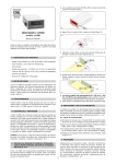
SP6NXCTUL
,
User s Guide
,
User s Guide
Ceiling Speaker
Frame Construction Ceiling Installation
1
Take the cutout template from the packaging box and
punch out along the larger perforated circle. Place
the cutout template against the bottom of the ceiling and
trace the inside of it. Carefully cut out the ceiling material
along the circle.
SP6NXCTUL
Ceiling Speaker
Suspended Ceiling Installation
4
Loosen the four screws on the front baffle(counter
clockwise) 1/2 turn. Then tighten the screws (clockwise)
until the dog legs clamp the speaker to the ceiling.
CAUTION Do not over tighten screws.
1
Remove the ceiling tile where the speaker is to be installed
2
Cut the hole in the tile. See step 1 of the Frame Construction
Ceiling Installation section on the back.
3
Painting the Speaker Baffle
Cut along the smaller perforated line of the cutout
template, marked as paint shield. Push it into the front
baffle of the speaker. Paint the front. Remove the paint
shield after the paint has dried.
Application diagram
Bring the speaker cable through the hole of the cut tile,
then reinstall the tile.
From
Power
Amplifier
To Speaker
Conduit
●
TH
RU
1.9
70
V
3.8
7.5
3.8
TH
RU
Apply 4 pieces of black putty
(supplied),equally spaced 90°
apart, to the upper inside
edge of the grille.
Power Amplifier
Speaker 1
Speaker 2
Speaker 3
Parallel Hookup Wiring Diagram
2-w ay, ceiling speaker with metal back can
65 Hz to 20 kHz,
60 Watts RMS
120 Watts PEAK
Nominal sensitivity......................
88 dB, 1W@1m
Nominal coverage angle..............
110° conical coverage
Nominal impedance .................... 8 ohms
Transformer taps ....................
70V:: 30W, 15W, 7.5W, 3.8W, 1.9W, 8 ohms
100: null, 30W, 15W, 7.5W, 3.8W, 8 ohms
Woofer...........................................
6.5" (165 mm) polypropylene cone
with moisture resistant coating
Tweeter..........................................
3/4" (19 mm) silk dome
Overload protection.......................
Full range power limiter with the 8 ohm direct
input only, protecting the tweeter, woofer, and
crossover.
General
Listings ........................................
Compliances ................................
Warranty.......................................
PO
DVD/VCR Combo
S
TPUT
OU
C
Storage: -40 to +158 °F (-40 to +70 °C) /
10% to 90%, noncondensing
Operating: +32 to +122 °F (0 to +50 °C) /
10% to 90%, noncondensing
UL1480
CE
1 years parts and labor
NOTE: All nominal level are at ±10%.
NOTE: Specifications are subject to change without notice.
68-1065-01 Re v. B
06 06
E
V
10 L/MUT
R
VO
O)
L
(MON
WER
V X
12 MA
3A
M
CO
70V
70
s
4/8
Ohm
Mini Power Amplifier
Variable
V-rails
E
MUT
ME
LU
VO
5
Projector
Speak Grilles
Loosen the four screws on the front baffle (counter
clockwise) 1/2 turn. Then tighten the screws(clockwise)
until the dog legs clamp the speaker to the ceiling.
CAUTION Do not over-tighten screws!
V-rails
7
Connect a secondary support line from he seismic tab
to a secure support point (see step 5 on the back).
8
Apply 4 pieces of black putty (supplied),equally spaced 90°
apart, to the upper inside edge of the grille (see step 5 on
the back).
Install the speaker grille.
Volume/Mute Controller
Packaging
6
Speaker type..................................
Frequency range...........................
Power handling..............................
Temperature/humidity .................
O)
ON
(M
Composite
Audio RCA
Connect the wires to the speak terminal clips (see step 2
on the back).
Acoustic & Electrical
To Speakers
C-ring
Seismic Tab &
Supprot Line
Specifications:
Replace the top cover and tighten the screws.
Insert the speaker through the bottom of the hole in
the ceiling.
TE
V
Cover
3
TED
LIS 3
1T2.E.
I.T
US
MO
RE
Adjusting the Tap Selector
4-pole Captive
Screw Connector
Remove the adjacent tile. Place 2 V-rails and 1 C-ring
across the tile where speaker is to be installed. Insert the
speaker through the bottom of the hole in the ceiling tile.
VGA w/
Audio Cable
TS
30
15
Enlarged to
Show Detail
4
INPU
7.5
15
30
Remove the top cover to access the speaker connector.
Attack the speaker wires to the 4-pole captive screw
connector. Insert the 4-pole captive
screw plug into the connector on back of the speaker.
Install the conduit and secure the connections.
Connect a secondary support line from the seismic tab to a
secure support point. Set the rotary tap selector and install
the speaker grille.
0V
2
5
10
Cut Material
Trace template.
Two-way Ceiling
Speakers
PC
C-rings
Speakers