1
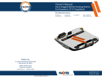
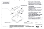
Owner’s Manual
Havis Rugged Hub
DS-DA-602
Installation & Cable Management (continued)
3) Secure Rugged Hub to mounting surface.
OPTION A: Typical Docking Station
OPTION B: Typical Universal Tray
Align holes on bottom of Rugged Hub
with two (2) holes in panel and secure
from back side using Hardware Kit Item 4a.
Torque screws to 14 in-lbs ± 10%.
Align holes on top of Rugged Hub with
three (3) holes in panel and secure from
front side using Hardware Kit Item 4b.
Torque screws to 14 in-lbs ± 10%.
Before Beginning
Havis is pleased to provide this Owner’s Manual to aid in the proper installation and use of
the DS-DA-602 Rugged Hub.
For questions regarding the set-up of your DS-DA-602 Rugged Hub, please contact Havis
at 1-800-524-9900 or visit www.havis.com for additional product support and information.
• THE POWER CABLE INCLUDED WITH THE DS-DA-602 IS UNIQUE TO THIS PRODUCT.
DO NOT USE THE DS-DA-602 POWER CABLE WITH ANY OTHER HAVIS DEVICE.
DO NOT USE ANY OTHER HAVIS DEVICE’S POWER CABLE WITH THE DS-DA-602.
• READ ALL INSTRUCTIONS THOROUGHLY BEFORE BEGINNING INSTALLATION.
4) Connect all required cables between peripheral devices and Rugged Hub,
then reinstall the Strain Relief Bracket as shown with fastener retained
from Step 1.
Specifications
Power Supply Input
9-24V DC-In
Dimensions
5.1” ( 12.9 cm) W x 3.3” ( 8.4 cm ) D x 1.0” ( 2.5 cm ) H
Weight
0.6 lbs ( 0.3 kg )
Operating Environment
-20° C to 65° C ( -4° F to 149° F )
Storage Environment
-30° C to 70° C ( -22° F to 158° F )
FCC Statement
5) As needed, use Zip Ties supplied in Hardware Kit to further strain relieve excess
cable lengths. Be certain to allow for a service loop to accomodate the full range
of intended motion.
This device complies with the requirements of the Code of Federal Regulations listed below:
FCC Title 47 CFR, Part 15 Class A for a digital device.
Operation is subject to the following two conditions:
(1) This device may not cause harmful interference, and
(2) This device must accept any interference received, including interference that may
cause undesired operation.
NOTE: This equipment has been tested and found to comply with the limits for a Class A digital device,
pursuant to part 15 of the FCC Rules. These limits are designed to provide reasonable protection against
harmful interference when the equipment is operated in a commercial environment. This equipment
generates, uses, and can radiate radio frequency energy and, if not installed and used in accordance
with instruction manual, may cause harmful interference to radio communications. Operation of this
equipment in a residential area is likely to cause harmful interference in which case the user will be
required to correct the interference at his own expense.
www.havis.com
1-800-524-9900
DS-DA-602_OMN_5-14
Parts Included
Installation & Cable Management
1. Rugged Hub
3. CD with Driver Software
Strain Relief
Bracket
2. Cables
a. USB Cable
b. Power Cable
4. Hardware Kit
a. Machine Screw, Pan Head,
#6-32 x 1/4” Long, #2 Phillips Drive,
with Adhesive Patch (2)
b. Thread-Forming Screw, Pan Head,
#6-32 x 1/4” Long, #2 Phillips Drive (3)
c. Zip Ties (2)
• THE DOCKING STATION AND/OR UNIVERSAL TRAY DEPICTED IN THESE INSTRUCTIONS MAY NOT
PRECISELY MATCH YOUR PRODUCT, HOWEVER THE INSTRUCTION STEPS REMAIN APPLICABLE.
• IF MOUNTING RUGGED HUB TO ANY SURFACE OTHER THAN A HAVIS DOCKING STATION OR
UNIVERSAL TRAY USE THE APPROPRIATE FASTENER AND TORQUES FOR YOUR INSTALLATION.
1) Remove Strain Relief Bracket from Rugged Hub. Be sure to retain fastener
for reassembly in Step 4.
• THE POWER CABLE INCLUDED WITH THE DS-DA-602 IS UNIQUE TO THIS PRODUCT.
DO NOT USE THE DS-DA-602 POWER CABLE WITH ANY OTHER HAVIS DEVICE.
DO NOT USE ANY OTHER HAVIS DEVICE’S POWER CABLE WITH THE DS-DA-602.
Port Replication and Fuse
2) Identify your required mounting configuration and select the appropriate
fasteners from the Hardware Kit:
OPTION A: If the back side of the panel to which the Rugged Hub is intended to be mounted is
accessible, use Hardware Kit Item 4a. This is typically a Docking Station mounting configuration.
OPTION B: If the back side of the panel to which the Rugged Hub is intended to be mounted is
not accessible, use Hardware Kit Item 4b. This is typically a Universal Tray mounting configuration.
Ethernet RJ45
10/100
USB 2.0 (out)
Type A
USB 2.0 (in)
Type B
Power Input
9-24V DC
2.0 Amp Fuse
(Top of Rugged Hub)
LED Diagnostics
USB Indicators (4)
Power Indicator
LED
USB Indicators (4)
Power Indicator
Color
OPTION A
OPTION B
Status
Green
Port is available
Off
Port has an over current
Red
Input Power is between 9V - 24V
Off
Voltage less than 9, or more than 24
( Bottom view of Rugged Hub)
www.havis.com • 1-800-524-9900