1
USRobotics® Courier® M2M 3G Cellular Gateway
User Guide & Technical Documentation
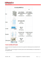
USR3510, USR803510
Revision: 1.00
Copyright 2015 U.S. Robotics Corporation
1|Page
Table of Contents
Table of Contents .......................................................................................................................................... 2
User Guide .................................................................................................................................................... 4
Introduction............................................................................................................................................... 4
Base Unit Hardware .................................................................................................................................. 5
Expansion Cards ........................................................................................................................................ 6
USR Universe ............................................................................................................................................. 8
Custom Developer Images ........................................................................................................................ 8
Network Interfaces .................................................................................................................................... 8
Installing the Gateway ............................................................................................................................... 9
Configuring the Base Unit ....................................................................................................................... 19
Configuring Expansion Cards ................................................................................................................... 63
Hardware Guide .......................................................................................................................................... 71
Mechanical Drawings .............................................................................................................................. 71
IP-65 requirement ................................................................................................................................... 72
Front and Back Panels ............................................................................................................................. 73
LED Descriptions ...................................................................................................................................... 76
Main Board Specifications ....................................................................................................................... 77
Expansion Card Specifications ................................................................................................................. 78
RF Specifications ...................................................................................................................................... 88
Ethernet Specifications............................................................................................................................ 93
Environmental Specifications .................................................................................................................. 97
Power Requirements ............................................................................................................................... 97
Internal Power Circuits ............................................................................................................................ 98
SIM Card Requirements ........................................................................................................................ 100
Certification and Operator Approvals ................................................................................................... 101
USR Universe Guide .................................................................................................................................. 109
Introducing the USR Universe ............................................................................................................... 109
Creating an Account .............................................................................................................................. 109
Signing In ............................................................................................................................................... 111
Activating a Gateway Using USR Universe ............................................................................................ 112
Revision: 1.00
Copyright 2015 U.S. Robotics Corporation
2|Page
Groups ................................................................................................................................................... 114
Devices .................................................................................................................................................. 124
Users ...................................................................................................................................................... 138
Managing Software ............................................................................................................................... 141
Editing Your Account ............................................................................................................................. 151
Troubleshooting ........................................................................................................................................ 153
Licenses ..................................................................................................................................................... 158
Revision: 1.00
Copyright 2015 U.S. Robotics Corporation
3|Page
User Guide
The USRobotics M2M Cellular Gateway User Guide explains
how to install and activate your gateway and configure your
device for use.
This guide is designed for:
Distributors
System integrators
Field engineers
Gateway hardware specifications and technical information are available in the Hardware Guide section
of this document. Information about deploying gateway firmware, configuration and software updates is
available in the Provisioning Server Guide section of this document.
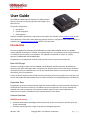
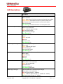
Introduction
The Courier M2M Cellular Gateway from USRobotics provides LAN to WWAN and Serial to WWAN
routing and GPS functionality in a simple, cost-effective base unit. The gateway can be configured locally
or remotely from a PC,tablet, or smartphone. The USR3510 is certified on all major U.S. cellular
operators (CDMA/EvDO and WCDMA/HSPA).
The gateway is pre-loaded with an RS232 serial interface card in its primary expansion slot.
Base Unit Design
The base unit design features Serial-to-WWAN, LAN-to-WWAN, and GPS interfaces, advanced error
detection, and repair watchdogs. When a component or software process loses connectivity, the device
automatically resets or repowers itself. You can also schedule the device to reset at specific intervals to
ensure daily, error-free operation.
Finally, the device can be monitored and provisioned remotely, which vastly reduces the technician time
on site, and enables firmware updates and new software features to be deployed quickly and efficiently.
Expansion Slots
The gateway can be user-customized with expansion cards available from select electronics distributors.
The RS232 serial interface card that is pre-loaded in the primary expansion slot can be removed and
replaced with another expansion card, and the secondary expansion slot can be loaded with an
expansion card. Contact a USRobotics Sales representative for more details.
Feature Overview
Reliability and Security
Software and hardware watchdogs continually monitor for loss of connectivity and will repair the
problem if detected
Software and configuration images are protected with digital signatures
Revision: 1.00
Copyright 2015 U.S. Robotics Corporation
4|Page
Secure, redundant firmware and configuration images ensure the unit can revert to previous
working settings if a problem is detected
Management functions are protected by certificate or password and applied over encrypted links
Flexibility
Hardware expansion slots allow for additional radio and/or wired interfaces
Expansion cards are designed with board-edge connectors for easy installation and replacement in
the field
Hardware and software development kits are available to partners for developing custom expansion
cards and software images
Provisioning
The USR Universe allows for efficient deployment of firmware, configuration file and developer
image updates to multiple gateways at once.
More Resources
USR3510 M2M Cellular Gateway Datasheet (US)
USR803510 M2M Cellular Gateway Datasheet (WCDMA - EMEA)
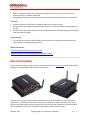
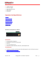
Base Unit Hardware
The mechanical housing for each base unit is identical. Internally, the main board is also identical and is
designed around a WWAN module and Ethernet interface.
The gateway can be user-customized with Option expansion cards available from select electronics
distributors. The RS232 serial interface card that is pre-loaded in the primary expansion slot can be
removed and replaced with another expansion card, and the secondary expansion slot can be loaded
with an expansion card. Contact a USRobotics Sales representative for more details.
Revision: 1.00
Copyright 2015 U.S. Robotics Corporation
5|Page
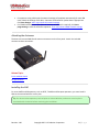
The base unit consists of:
Light weight aluminum housing with DIN rail and wall mounting options
Two SMA-type antenna interfaces: WWAN Main and WWAN Div/GPS
WLAN, GPS, System, and WWAN LEDs showing system status and signal strength
10/100 MB/s RJ-45 Ethernet interface
Primary expansion slot pre-loaded with Option serial card - CG1101
9-33 VDC power in with Micro-Fit™, dual row, 4-circuit connector
Available secondary expansion slot
Internal main board with WWAN module, Ethernet interface and GPS
Freescale i.MX280 450MHz Processor
o 64 MB Ram
o 128 MB Flash
o GTM68X WWAN module
Base Unit Versions
Two versions of the base unit exist:
USR3510
o
o
Contains the GTM689 cellular radio module which provides CDMA/EVDO and WCDMA
technology.
Used in the U.S. and Canada and has the correct certification and approvals for these countries.
USR803510
o
o
Contains the GTM681 cellular radio module which provides WCDMA technology.
Used in Europe and has the correct certification and approvals for these countries.
Related Topics
Expansion Cards
Mounting options
Mechanical Drawings
Front and back Panels
Expansion Cards
The USRobotics M2M Cellular Gateway is compatible with Option expansion cards. For custom
solutions, Option also licenses a hardware development kit. Third parties can design their own
expansion cards to fit specific needs.
The expansion cards offered by Option include:
WLAN expansion card (CG2101)
Low cost serial card (CG1101) included in the base unit
Revision: 1.00
Copyright 2015 U.S. Robotics Corporation
6|Page
Industrial serial card (CG1102)
PoE Ethernet switch (CG1103)
Basic Ethernet switch (CG1104)
Developer card (CG1105)
WLAN Expansion Card - CG2101
Provides 802.11abgn
Simultaneous Access Point and Station mode for providing service or connection as a wireless LAN
Failover to WLAN client for WAN connectivity
Dual SSID
Low Cost Serial Card - CG1101
Provides a single RS-232, 921.6Kbaud maximum speed.
Industrial Serial Card - CG1102
One RS-232 port with 921.6 Kbaud maximum speed.
2 KV isolated RS-485 serial port, 921.6 kbaud, full duplex or half duplex; 2 wire or 4 wire with
switchable termination.
Basic Ethernet Switch - CG1104
4-port 10/100Base-T
µSD card
PoE Ethernet Switch - CG1103
Power over Ethernet board. (requires special power supply)
4-port 10/100Base-T with 2 ports class 4 or 4 ports up to class 3 PoE
µSD card
Developers Expansion Card - CG1105
Extended format with headers on all interfaces to attach to development equipment
Pre-wired RS-232 port, GPIO connected temperature sensor, a relay and SD card slot.
Related Topics
Installing Expansion Cards
Configuring Expansion Cards
Revision: 1.00
Copyright 2015 U.S. Robotics Corporation
7|Page
USR Universe
The USR Universe is the configuration and deployment mechanism for the USR Gateway. From the
factory, the base unit is pre-configured for a RS232 serial interface card.
On power-up, the gateway connects to the USR Universe over the wired Ethernet port and automatically
downloads the appropriate update. If the Ethernet interface is unavailable, then the gateway uses the
WWAN interface to download the updates.
Tip: You can set the USR Universe to enable or disable the automatic downloads.
The Gateway downloads the following files from the USR Universe:
Gateway firmware: System firmware provided by USRobotics.
Gateway developer image: customized software that provides additional functionality to the
gateway or controls third-party expansion cards.
Gateway config file: configuration settings that can be applied to one or more gateways
Gateway GOBI firmware image: software that updates changes to wireless operator firmware
Related Topics
USR Universe Guide
3G Connection Tab
Custom Developer Images
To extend the base unit functionality provided by the gateway firmware, you can install developer
software images onto an overlay file system and adapt the gateway to specific needs. Developer images
can be created for custom applications and middleware, and to control third-party expansion cards.
Option licenses a software development kit which allows third parties to design developer images. For
information on the Option CloudGate developer program, contact Option Customer Support.
Related Topics
USR Universe Guide
Network Interfaces
For connecting to the Internet, the base unit comes with an Ethernet interface and a WWAN (3G)
interface. An optional WLAN interface is available only when the WLAN expansion card is installed.
Revision: 1.00
Copyright 2015 U.S. Robotics Corporation
8|Page
While the WWAN network interface is always a direct connection to the Internet, or WAN, the Ethernet
interface and optional WLAN interface can act as either a WAN or a local Area Network (LAN). The LAN
interface allows local devices to connect to the Internet through the gateway.
The network interfaces available on the gateway are:
Ethernet interface: can be a WAN or LAN connection depending on the behavior of the WAN/LAN
switchover feature at start-up or can be set manually.
WWAN interface: always a WAN connection because it connects directly to the internet.
WLAN interface: optional Wi-Fi expansion card can be configured as either a WLAN client, which will
act as a WAN interface, or as a WLAN access point, which will act as a LAN interface.
Choosing a WAN or LAN Interface
The gateway can have only one WAN connection at a time. However the gateway can be connected to
several different LAN networks simultaneously.
In choosing the network interface, you can specify:
Manual: the network interface is selected through the embedded web interface on the Home page.
Automatic: a priority list defines which network interface to use to connect to the WAN/internet.
The network interface at the top of the list will try to connect to the WAN/internet first. If this
succeeds then the gateway continues to use this network interface to connect to the WAN/internet.
If the connection to the internet fails, the gateway tries the second interface in the priority list and
so on. The priority list is defined in the embedded web interface on the Home page.
Warning: In firmware versions 1.12.0 and older, the ability to choose between automatic mode and
manual mode and to set a connection priority list are not available. These firmware versions always
try to connect to the internet over the Ethernet interface first. When this interface is not able to
connect to the internet, the gateway will try to connect to the internet via the WWAN interface.
Related Topics
Configuring the Base Unit
Ethernet Tab
3G Connection Tab
WAN/LAN switchover feature
Installing the Gateway
To install the base unit out of the box, review the installation requirements and then follow the
installation steps listed below. For information about customizing the base unit, learn about installing
expansion cards and provisioning the device with a custom developer image.
Revision: 1.00
Copyright 2015 U.S. Robotics Corporation
9|Page
Installation Requirements
Gateway base unit
Included power supply
Included WWAN antennas
Ethernet cable
Web browser on a laptop or smartphone.
A service plan from a wireless service provider.
o One of the following US wireless service providers:
Sprint
Verizon Wireless
AT&T (requires SIM)
T-Mobile (requires SIM)
o For non US wireless service providers, any WCDMA based network will work.
Browser Requirements
For the Provisioning Server:
Chrome 27.0 (.1453.110 m)
Firefox 21.0
Internet Explorer 9 (.0.8112.16421)
Internet Explorer 10 (.0.9200.16540)
For the gateway embedded web interface:
Internet Explorer 9
Safari 5.1
Firefox (Windows 21.0, Mac 12.0)
Chrome (Windows 27.0.1453.110, Mac 26.0.1410.65)
Opera (Windows 12.02, Mac 12.10)
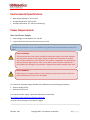
Installation Overview
Before installing your gateway device, read the safety guidelines carefully. Not following these
guidelines can cause harm to the gateway, yourself or other persons.
To install the base unit:
1. Attach the antennas.
2. Install the SIM, if your wireless operator is using a SIM card, or make sure that a service plan is
associated with your device (for Sprint and Verizon).
3. Register the Gateway on the Provisioning Server.
4. Power on the Gateway.
5. Connect the Gateway to a laptop and log in to the embedded web interface.
6. Select a wireless operator in the 3G Connection tab.
Revision: 1.00
Copyright 2015 U.S. Robotics Corporation
10 | P a g e
For operators using a SIM card, the network settings will populate automatically for most SIM
cards. Check the settings of the APN , Username and Password. Update them if appropriate.
Click Save changes. Learn more about 3G network settings
For CDMA based operators (for Sprint or Verizon, no SIM card is required), click Start
programming to start the activation sequence. Learn more about CDMA network settings
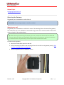
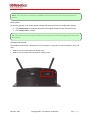
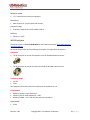
Attaching the Antennas
The base unit has two SMA-female antenna connectors on the front panel. Attach the included
antennas to these connectors.
Related Topics
Front and Back Panels
RF Specifications
Installing the SIM
For some UMTS and 3G operators, such as AT&T, T-Mobile and European operators, you must install a
SIM card associated with the service plan.
Tip: For other wireless operators, such as Sprint or Verizon Wireless, make sure a service plan is
associated with the device before continuing the installation.
Revision: 1.00
Copyright 2015 U.S. Robotics Corporation
11 | P a g e
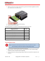
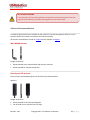
To install the SIM:
1. Using a T6 Torx screwdriver, remove the four screws from the top plate on the back panel, and then
remove the plate.
2. Insert the SIM into the SIM slot.
3. Replace the top cover plate and screws.
Related Topics
Selecting a Wireless Operator
Activating the Gateway
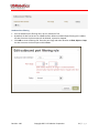
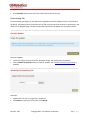
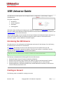
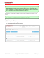
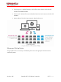
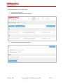
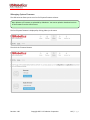
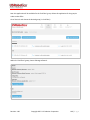
When you activate the gateway, you add the device to the USR Universe. The USR Universe allows you
to configure one or more devices with the same firmware, configuration, and developer images.
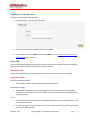
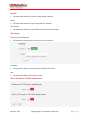
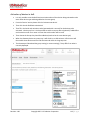
To activate a gateway using a computer:
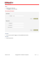
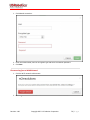
1. Open an internet browser and go to the USR Activate URL: http://www.usr.com/activate/3510
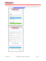
2. If you don’t have a user name and password, click Don't have an account yet? and follow the
instructions.
Revision: 1.00
Copyright 2015 U.S. Robotics Corporation
12 | P a g e
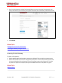
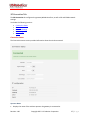
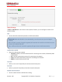
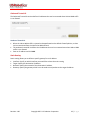
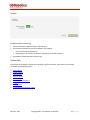
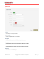
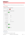
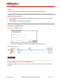
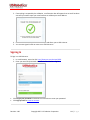
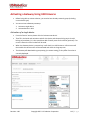
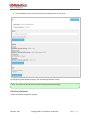
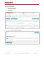
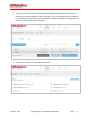
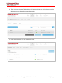
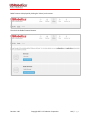
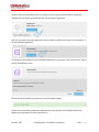
3. Sign in and complete the Activate Device page. Select or enter a User group, (your personal user
group is the same as your username), the type of activation, the serial number, and activation code.
4. Click Activate.
Related Topics
Creating an Account on the USR Universe
Activating the Gateway Using the USR Universe
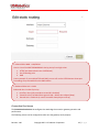
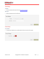
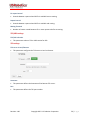
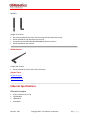
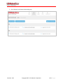
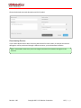
Powering On the Gateway
To power on the gateway:
1. Plug the power supply into the power connector on the back of the unit and into a power source.
2. Observe the LEDs on the front panel. The gateway attempts to connect automatically with the USR
Universe and download the appropriate firmware, developer image, and configuration file. When
the power-on sequence is complete, the System and WAN LEDs on the front panel turn green.
Related Topics
LED Descriptions
Revision: 1.00
Copyright 2015 U.S. Robotics Corporation
13 | P a g e
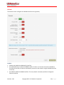
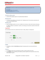
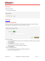
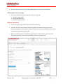
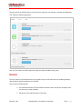
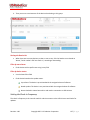
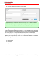
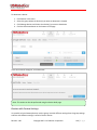
Selecting a Wireless Provider
For the minimum, out-of-the-box installation of the base unit, you have to connect the device to a
laptop and use the embedded web interface to select the appropriate wireless provider firmware.
IMPORTANT: When using the USRobotics USR803510 (GSM/WCDMA only version), selecting the
wireless operator is not needed and you can immediately go to step 7 on this page.
To connect the gateway to a laptop and select a wireless provider:
1. Connect an Ethernet cable to the Ethernet port on the gateway front panel and a network port on a
laptop or computer.
2. In a web browser, go the URL: 192.168.1.1.
3. In the login screen, enter the default username admin and password admin.
4. Click the 3G Connection tab in the top menu bar.
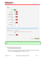
5. Scroll down to the Radio firmware selection field for the wireless operator firmware options.
6. Select the appropriate wireless provider and click Save changes.
Revision: 1.00
Copyright 2015 U.S. Robotics Corporation
14 | P a g e
Tip: When using an AT&T SIM card, select AT&T. For all other operators using SIM cards, select UMTS
generic.
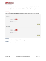
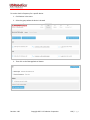
7. Proceed with the wireless provider selection.
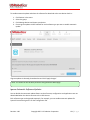
For Verizon Wireless and Sprint service
Make sure the service plan is already associated with the unit (MEID). Scroll down to the CDMA
section and click Start programming to complete the activation.
Revision: 1.00
Copyright 2015 U.S. Robotics Corporation
15 | P a g e
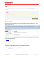
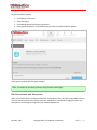
For all SIM card based operators
The network settings populate automatically for most SIM cards. Scroll down to the Network
Settings section and check the APN, Username, and Password fields. Update if necessary and
click Save changes. If the service plan requires a PIN code, scroll down to the PIN Settings
section, enable and enter the PIN code, and click Save changes.
Related Topics
Configuring the Base Unit
3G Connection Tab
Installing Expansion Cards
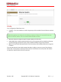
Gateway expansion cards are easy to install either during staging by a distributor or system integrator,
or in the field by a technician.
Expansion cards are designed to fit in one of two expansion slots accessed from the unit’s front or back
panels. In general, cards with antenna interfaces, such as the WLAN card, are installed in the back slot to
avoid interference with the 3G antennas on the front of the base unit.
Tip: Another way to determine the appropriate slot, is to look at the card connector. Cards with the
small connector are installed in the rear slot. Cards with the large connector are installed in the front
slot.
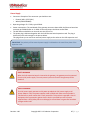
To install an expansion card:
1. Make sure the unit is powered off.
2. Using a T6 Torx screwdriver, remove the three screws from the bottom plate on the front or
back panel, and remove the plate.
3. With the expansion card in your hand, make sure the English labelling for any external
interfaces, such WLAN Antenna or Serial Port, are facing up. In this orientation, the card
connector is also right facing.
Revision: 1.00
Copyright 2015 U.S. Robotics Corporation
16 | P a g e
4. Slide the card into slot, using the side channels or grooves on the device to guide the card into
place. Make sure the screw holes line up.
5. Push gently until the card is flush with the housing.
6. Secure the card with the screws.
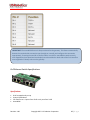
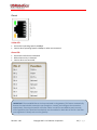
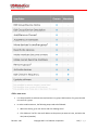
The following table lists the expansion cards available from Option and the slot.
Expansion Card
Slot
Wi-Fi Card (CG2101)
Back
Low Cost Serial Card (CG1101) included in the base unit
Front
Industrial Serial Card (CG1102)
Front
Basic Ethernet Switch (CG1104)
Front
PoE Ethernet Switch (CG1103)
Front
Developers Card (CG1105)
Front
Removing Expansion Cards
Note: The expansion card faceplate will deform if the card is pulled at the edge.
Do not attempt to remove the expansion card by pulling its edge!
1. Remove the Torx screws that fasten the card to the base unit.
2. Plug a connector into the mating connector on the expansion card. If the card has multiple
connectors, choose a connector near the right edge.
3. Remove the expansion card by pulling the plug or cable that is inserted into an expansion card
connector.
Revision: 1.00
Copyright 2015 U.S. Robotics Corporation
17 | P a g e
Related Topics
Configuring Expansion Cards
Mounting the Gateway
The gateway can be mounted on a wall or DIN rail.
IMPORTANT: All mounting hardware is installer provided.
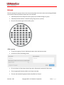
Mounting on a wall
The gateway can be mounted on a wall with six screws. The mounting holes in the base of the gateway
have a diameter of 4.3 mm. USRobotics recommends using screws with a minimum width of 4mm and a
minimum length of 30 mm (M4x30mm).
Tip: When choosing the mounting orientation of the unit, consider the direction of the cables and
antennas. Make sure cables are routed with sufficient ease to all connectors, and that the antennas
are unobstructed for easy positioning. The front panel LEDs should also be visible.
To wall mount the gateway:
1. Mark the six holes with a pencil on the wall.
2. Drill (if necessary) the holes in the mounting surface. Do not drill into the gateway housing. Click
here for a drawing of the mounting holes.
3. Mount the gateway with six M4x30mm screws
Revision: 1.00
Copyright 2015 U.S. Robotics Corporation
18 | P a g e
Mounting on a DIN rail
To mount the gateway on a DIN rail, use two DIN rail adapters. USRobotics suggests adaptors from
the following companies:
Phoenix Contact
DSB Marketing
Hammond
Configuring the Base Unit
When the gateway is connected to a laptop through an Ethernet cable, you can configure the device
locally using the embedded web interface. The web interface allows you to configure one device at a
time.
Tip: To provision a number of gateways at once, use the web interface to create a configuration file
and use the USR Universe to download the file to multiple devices.
Learn how to log on to the embedded web interface
The web interface displays a number of tabs based on the expansion cards installed. For the base unit
with the included serial card, the following default tabs are available: Home, Ethernet, 3G Connections,
Firewall, Connection Persistence, Provisioning, System, Plugin and VPN.
Revision: 1.00
Copyright 2015 U.S. Robotics Corporation
19 | P a g e
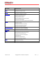
Click this tab
To do these tasks
Home
VPN
Verifying the Internet Connection
Checking the Firmware Version
Disabling the WAN/LAN Switchover Feature
Managing IP Configuration Settings
Configuring the WWAN Interface
Choosing a Wireless Operator
Setting Up SIM Parameters
Setting Up WWAN Connection Parameters
Choosing PIN Code Settings
Setting up Verizon Wireless or Sprint wireless operators
Setting Default Firewall settings
Setting Up the DMZ
Setting Up Inbound Port Forwarding
Setting Up Outbound Port Filtering
Setting Up Outbound Trusted IPs
Configuring the Connection Watchdog
Configuring the Automatic Timed Reset
Setting up Automatic updates
Setting up the Time Zone
Setting up Remote Access to the Gateway
Setting up a Dynamic DNS Service
Changing the Username and Password
Creating Log Files
Download a configuration file
Manually Resetting the Gateway
Setting up the serial port
Setting up GPS reporting
Creating and configuring IPSec tunnels
Revision: 1.00
Copyright 2015 U.S. Robotics Corporation
Ethernet
3G Connection
Firewall
Connection Persistence
Provisioning
System
Plugin
20 | P a g e
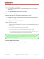
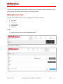
Logging On to the Base Unit
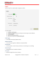
To log on to the embedded web interface:
1. In a web browser, go to the URL: 192.168.1.1.
2. Enter the user name and password, and then click Login.
Use the default username admin and password admin. You can change the default username
and password later if necessary.
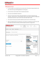
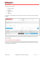
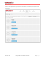
Home Tab
The Home tab displays the gateway connection status, the connection settings, the different available
LAN interfaces and the firmware and software versions installed.
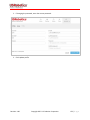
Connection status
Displays the type of Internet connection and reports if the unit is connected or not connected.
Connection settings
Internet connection enabled:
This parameter enables (Yes) or disables (No) the WAN interface.
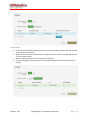
Connections strategy:
This parameter defines which interface should be chosen to connect to the internet (WAN
interface) in case multiple solutions are possible. Two possible solutions are available: Manual
and priority based.
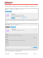
Manual
In manual mode, the interface with a blue background will be the one and only interface to the
internet (WAN interface).
In order to change the interface press on the "use this" button behind the interface you would
like to be the WAN interface.
Revision: 1.00
Copyright 2015 U.S. Robotics Corporation
21 | P a g e
Priority based
In priority based mode the gateway will first try to make a WAN connection with the interface
on the top row of the table.
When the first interface is unable to make a connection to the internet, the gateway will then
try the second interface.
When the second interface fails the next line will be tried.
In order to change the priorities, click on the arrows behind the interface you would like to
change.
I
Revision: 1.00
Copyright 2015 U.S. Robotics Corporation
22 | P a g e
IMPORTANT: The gateway decides that it's not connected anymore when:
- the Ethernet connection cable is removed.
- when a disconnect message of the network is received via the 3G connection
- when the WLAN connection is out of range.
This functionality can be extended when used together with the connection persistence feature.
LAN interfaces
Displays a list of the available LAN interfaces and their IP addresses.
VPN Tunnels
Displays a list of the active VPN tunnels.
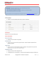
System information
Device serial number
Displays the serial number of the gateway
Firmware version
Displays the current version of the system firmware. System firmware is required for the
gateway to operate.
Image version
Displays the version of the developers image. This image is only required in case you need
features which are not part of the system firmware.
Configuration version
Displays the version of the configuration file.
A configuration file is not mandatory, it's a way to provision gateway settings to multiple units.
Revision: 1.00
Copyright 2015 U.S. Robotics Corporation
23 | P a g e
Interfaces Tab
The interfaces menu groups the settings of all connection technologies
Ethernet
3G Connection
WLAN Client
WLAN Access point
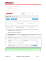
Ethernet Tab
The Ethernet tab configures the behavior of the Ethernet port on startup and manages IP nework
settings.
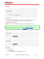
Enabled
Enables (Yes) the Ethernet interface on the main board of the gateway or disables (No) the
Ethernet interface
Revision: 1.00
Copyright 2015 U.S. Robotics Corporation
24 | P a g e
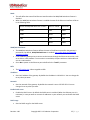
Mode
This will define the state of the Ethernet interface when the WAN/LAN Switchover feature is
disabled.
When the WAN/LAN switchover feature is enabled the state of the Ethernet interface will be as
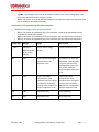
in the following table:
Result of WAN/LAN switchover feature
State of "Mode"
End result
WAN
LAN
WAN
WAN
WAN
WAN
LAN
LAN
LAN
LAN
WAN
WAN
WAN/LAN Switchover
The WAN/LAN switchover feature defines the state of the Ethernet port after the gateway is
powered on. By default, WAN/LAN Switchover is enabled. Learn more about the WAN/LAN
switchover feature.
If set to Yes the gateway tries to connect to the Internet through the Ethernet connection, such
as an ADSL or cable modem. If a connection is unavailable, the port switches to LAN mode and
acts as a LAN interface.
Set to No to power on the Ethernet port as defined in the "mode" parameter.
MTU
The MTU packet size: Value range 68 to 1500
IP address
Sets the IP address of the gateway. By default the IP address is 192.168.1.1. You can change this
to any value you want.
Netmask
Sets the netmask of the gateway. By default the netmask is set to 255.255.255.0. You can
change this to any value you want.
Enable DHCP server
Enables the DHCP server. By default the DHCP server is enabled. (When the Ethernet port is in
LAN state). In case you want to use static IP addresses in your network you can disable the DHCP
server.
DHCP range
Sets the DHCP range for the DHCP server.
Revision: 1.00
Copyright 2015 U.S. Robotics Corporation
25 | P a g e
Lease time
Lease time is configurable from 2 minutes up to 24854 days.
DNS 1 and DNS 2
When the gateway is in LAN mode the DNS fields will be empty by default. As a result the gateway itself
will act as a DNS server. All the connected Ethernet devices will receive an DNS address which is equal to
the gateway's IP address (by default 192.168.1.1) When the DNS server inside the gateway can't resolve
the DNS request it will forward the request to the DNS server of the WAN connection.
When the gateway is in WAN mode the DNS address will be defined by the DHCP server of the internet
provider. When the DNS fields are changed to another value than the other IP address will be used for
the DNS server.
Reserved leases
Lists the DHCP leases which are assigned to a certain MAC address.
Click Add to assign another lease and link a MAC address to an IP address.
Active leases
Lists the active DHCP leases of the devices connected to the gateway.
Click Reserve to add the lease to the Reserve leases list.
Related Topics
WAN/LAN Switchover Feature
Revision: 1.00
Copyright 2015 U.S. Robotics Corporation
26 | P a g e
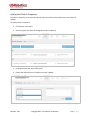
3G Connection Tab
The 3G Connection tab configures the gateway WWAN interface, as well as 3G and CDMA network
settings.
It includes the following sections:
Connection Status
General
Network Settings
PIN Settings
CDMA
Connection Status
The Connection status section provides information about the wireless network.
Operator Name
Displays the name of the wireless operator the gateway is connected to.
Revision: 1.00
Copyright 2015 U.S. Robotics Corporation
27 | P a g e
Signal Strength
Displays the received signal strength.
ECIO
Displays the energy per chip over the interference. This is a typical way to indicate the quality of 3G
networks.
Technology
Displays the technology used by the wireless operator.
Voice number
Displays the voice number linked to the SIM card for 3G wireless operators.
Revision: 1.00
Copyright 2015 U.S. Robotics Corporation
28 | P a g e
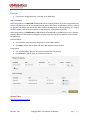
General
The General section configures the WWAN interface on the gateway.
Enabled
Enables and disables the WWAN (3G) interface,
Set to Yes (default) to enable the WWAN interface. If there is no Internet connection available on
the Ethernet interface, the device automatically connects to the network using the WWAN interface
on startup.
Set to No to disable the WWAN interface. The only network connection possible is through the
Ethernet interface.
Revision: 1.00
Copyright 2015 U.S. Robotics Corporation
29 | P a g e
Only upon traffic
By default, the device is always connected to the network and can send and receive data in both
directions: Internet to gateway, and gateway to Internet. To protect the device from unauthorized
access and ensure you only pay for the data you want to send, you can configure the device to
connect only when it has data to transmit.
Set to Yes to connect the device to the WWAN when it has data to send and disconnect it
immediately after. Note that when the device is disconnected, it is also unable to receive data.
USRobotics recommends enabling this feature only if you are interested in one way, gateway-toInternet data flow.
Set to No (default) to disable sending data only upon traffic.
IMPORTANT: Remote login to the gateway does not work when Only upon traffic is enabled.
Connect while on international roaming
Manages international roaming settings for a device installed in a vehicle.
If set to Yes, international roaming is enabled.
If set to No, international roaming is disabled. USRobotics recommends disabling this feature to
prevent high roaming costs.
IMPORTANT: National roaming is always allowed on the gateway. The Connect while on roaming
feature only has an impact on international roaming behavior.
WWAN Div Antenna present
Enables antenna diversity.
The base unit supports two antenna interfaces: WWAN with Diversity/GPS and WWAN Main. Using
both antennas ensures better reception in low coverage areas and increased throughput.
If set to Yes, antenna diversity is enabled and both physical antennas must be installed.
If set to No, make sure only one antenna is connected to WWAN Main on the front panel.
IMPORTANT: Installing one antenna with diversity enabled (set to Yes), results in poor or unstable
performance. Make sure that diversity is disabled when there is only one antenna installed.
WWAN Passthrough Mode
By default, Passthrough Mode is disabled (set to No).
If set to Yes, the connected laptop receives an IP address from the wireless operator through the
gateway.
IMPORTANT: When pass-through is active, data send to port 80 will always redirect to the WebGui of
the gateway!
Revision: 1.00
Copyright 2015 U.S. Robotics Corporation
30 | P a g e
Allow ICMP
Allow ICMP messages to pass the firewall. Most important usage is to allow ping to function on the
WAN interface.
Limit Wireless Mode
Limit wireless mode to a specific technology. This is useful when on the limit of coverage of one
technology to avoid ping/ponging between 2G and 3G for example.
MTU
The MTU packet size: Value range 68 to 1500
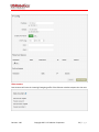
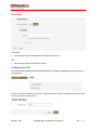
Radio firmware selection
Selects the wireless operator firmware the device will use on the network.
IMPORTANT: When using the USR803510 base unit (this is the version without CDMA technology),
you don't have to select the wireless operator. The device uses the UMTS Generic setting.
If Verizon Wireless or Sprint is selected, the web interface jumps to the CDMA section. Click Start
Programming to provision the unit for CDMA.
If UMTS Generic is selected for T-Mobile or any operator not listed, you may be required to enter a
PIN code. In the PIN code section, enter the appropriate settings and click Save changes to provision
the unit for UMTS 3G.
If AT&T is selected, you may be required to enter a PIN code. In the Pin Code section, enter the
settings and click Save changes to provision the unit for AT&T 3G.
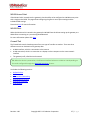
Connection Hunting
Connection hunting is a feature that allows the gateway to actively search for another network in case
the primary network is not available.
IMPORTANT: The connection hunting feature is only available on USR3510 WCDMA + CDMA
When enabled, a new section of the menu will appear allowing the user to select which other networks
the gateway should try to connect to in case the primary connection cannot be established.
The fallback time field allows selecting the time the gateway needs to try to connect to each of the
alternative networks before trying the next network.
Revision: 1.00
Copyright 2015 U.S. Robotics Corporation
31 | P a g e
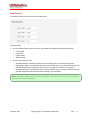
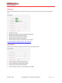
Network Settings
If AT&T or UMTS Generic is the chosen wireless operator firmware, you can configure a number of 3G
network settings.
APN
Sets the APN value automatically based on the SIM card installed.
IMPORTANT: When the APN which is set automatically, is not the correct one, you can change it
manually.
When the APN is manually changed, the gateway will remember this and will use this APN every time
it detects this individual SIM card.
When a different SIM card is inserted the gateway will again choose the APN automatically.
Authentication method
Selects the authentication method:
o Automatic: (default). Uses PAP authentication for connecting to the network, followed by CHAP
authentication.
o PAP: Uses PAP authentication protocol for connecting to the network.
o CHAP: Uses CHAP authentication protocol for connecting to the network.
o NONE: No authentication protocol used.
Username
Defines a user name if required by the wireless network subscription.
Password
Defines a password if required by the wireless network subscription.
Network selection method
Sets the network selection method when roaming:
Revision: 1.00
Copyright 2015 U.S. Robotics Corporation
32 | P a g e
o
o
Automatic: Registers the device to the network corresponding to the SIM card installed. When
roaming, the device connects to the roaming partner designated by the wireless operator.
Manual: Scans for networks and then lets you select a network different from your home
network.
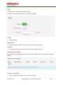
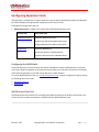
PIN Settings
When you select AT&T or UMTS Generic as the wireless operator, you may have to enter a PIN code.
Enable PIN
Enables the PIN code and displays a field for entering the value.
Save PIN
Automatically saves the PIN code.
Revision: 1.00
Copyright 2015 U.S. Robotics Corporation
33 | P a g e
CDMA
If Verizon Wireless or Sprint is the chosen wireless operator, click Start programming to provision the
gateway.
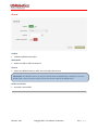
Ethernet Switch
When the Ethernet expansion board is inserted into the gateway a new item "Ethernet Switch" will be
listed in the interfaces tab.
only LAN functionality is available on the Ethernet Switch outputs, no WAN functionality.
3 fields are available in this tab:
General
IP Config
Data Counters
General
In the general section of the Ethernet switch these settings can be selected :
Enabled: Yes / No
The MTU packet size: Value range 68 to 1500
Revision: 1.00
Copyright 2015 U.S. Robotics Corporation
34 | P a g e
IP Config
The IP configuration field allows to set:
IP address: This is the IP address on which the gateway will be reachable from the Ethernet switches
network
Default the gateway uses subnet 4 on the Ethernet switch card. Subnet 1 is reserved for the main
Ethernet interface, Subnet 2 & 3 for the WLAN SSID1 & SSID2 interfaces.
Net mask: Allows to configure a specific netmask, default 255.255.255.0
Enable DHCP Server: When enabled the DHCP service of the gateway will be available to all devices
connected through the Ethernet switch, when enabled the address range can be selected
DNS 1 & 2: these fields allow specification of custom primary and secondary DNS servers using their
IP address
The reserved and active leases table manages the devices’ ability to connect to ports of the Ethernet
Switch card. To add a device manually to the list click the "add" button. Host name, Mac & IP address
are required. A specific lease time can be selected.
Revision: 1.00
Copyright 2015 U.S. Robotics Corporation
35 | P a g e
Data counters
Data counters will trace the incoming & outgoing traffic of the Ethernet switches outputs since last start.
Revision: 1.00
Copyright 2015 U.S. Robotics Corporation
36 | P a g e
WLAN Access Point
If the WLAN Card is inserted into the gateway it has the ability to be configured as a WLAN access point
with a single or dual SSID. This page allows configuring the generic access point settings and the
individual SSID settings.
Please click here for more information
WLAN Client
When the WLAN card is inserted in the gateway the WLAN Client tab allows setting up the gateway as a
WLAN Client connecting to a pre existing WLAN Network
For more information please click here.
Firewall Tab
The Firewall tab controls how data passes from one type of interface to another. There are three
different sources or destinations for gateway data:
A WAN interface, which is a connection to the Internet
A LAN connection, which is a connection to a laptop or other computer on the same network
interface
The gateway itself, called the Local network
TIP: When the device is powered on, the Ethernet interface behaves as a WAN or LAN depending on
the mode configured through the WAN/LAN Switchover feature.
It includes the following sections:
Default Policies
DMZ
Inbound Port Forwarding
Outbound Port Filtering
Outbound Trusted IPs
Static Routing
Revision: 1.00
Copyright 2015 U.S. Robotics Corporation
37 | P a g e
Default Policies
The Default Policies section sets the basic firewall rules.
Default Policies
Sets the default firewall rules to accept or reject data flow between the following interfaces:
o
o
o
o
LAN to WAN
LAN to LAN
LAN to LOCAL
WAN to LOCAL
Sets the action for each rule:
o
o
o
Accepted: the data is allowed to pass from one interface type to the other interface type.
Rejected: the data is not allowed to pass form one interface type to the other interface type; the
gateway drops the data packets and sends a reject message to the source of the packets.
Dropped: the data is not allowed to pass from one interface type to the other interface type; the
gateway drops these data packets without sending a reject message.
NOTE: The WAN to LOCAL traffic is by default "Dropped". This makes sure that no traffic coming from
the Internet can enter the gateway.
Revision: 1.00
Copyright 2015 U.S. Robotics Corporation
38 | P a g e
DMZ
The DMZ section configures the demilitarized zone.
This feature forwards all incoming data to a specific IP address.
Enabled
Enables the DMZ.
WAN Interface
Selects the WAN interface the data will be coming from for forwarding.
IP Address
Sets the IP address for forwarding all data coming from a WAN interface.
Inbound Port Forwarding
The Inbound Port Forwarding section forwards data from a WAN interface to a designated IP address
and port.
Inbound Port Forwarding
Lists the inbound forwarding rules, up to a maximum of 40.
Revision: 1.00
Copyright 2015 U.S. Robotics Corporation
39 | P a g e
These rules allow you to forward data from a WAN interface to the IP address set in the destination
field.
The port forwarding rules have a higher priority than the DMZ rule!
Click Add to create a forwarding rule. Enter the port information and target IP address in the dialog
box and click Save.
Outbound Port Filtering
The Outbound Port Filtering section defines the data allowed to pass from the Local or LAN interface to
the WAN interface.
Revision: 1.00
Copyright 2015 U.S. Robotics Corporation
40 | P a g e
Outbound Port Filtering
Lists the outbound port filtering rules, up to a maximum of 20.
By default, all data can be sent to a WAN interface. When an outbound port filtering rule is added,
the data sent over the chosen port will be allowed, rejected or dropped.
Click Add to create a filtering rule. Enter the port range and select whether to Allow, Reject or Drop
the data sent over the chosen port and click Save.
Revision: 1.00
Copyright 2015 U.S. Robotics Corporation
41 | P a g e
Outbound Trusted IPs
The Outbound Trusted IPs section defines IP addresses that can be contacted when LAN-to-WAN traffic
is not allowed.
Outbound Trusted IPs
When the LAN to WAN traffic is rejected or dropped based on the default firewall policies, no data
can be transmitted from the LAN to the WAN network.
The outbound trusted IP list defines the IP addresses that can be contacted even when LAN-to-WAN
traffic is not allowed.
Enter an IP address and click Add.
Static Routing
Static routing allows you to define a specific gateway for an IP address
Interface: Specify on which interface you would like to have the static routing
Target: Specify the destination IP address.
Netmask: Specify the netmask of the destination IP address
Gateway: Specify the gateway which has to be used to send packets to the target IP address.
Revision: 1.00
Copyright 2015 U.S. Robotics Corporation
42 | P a g e
! Inbound Rules WAN -> LAN/LOCAL
Next is a list of the PORT FORWARDING rules by priority from high to low:
1. HTTPS (port determined in the >SYSTEM tab)
2. Port forwarding rules
3. DMZ
Priority example: If you enable HTTPS and DMZ, you can still use the HTTPS because those port
forwardings are processed before the DMZ redirect.
! Outbound Rules LAN -> WAN
Outbound rules in order of priority:
1. Port filter rules. (Only used when trusted IP is disabled)
2. Trusted IP rules (if enabled forces general LAN -> WAN rules to Reject/Drop)
3. General LAN -> WAN rule (in case of trusted IP always Reject or Drop)
Connection Persistence
The Connection Persistence tab configures the watchdogs that monitor gateway operation and
performance.
The following actions can be configured to make sure the gateway works properly.
Revision: 1.00
Copyright 2015 U.S. Robotics Corporation
43 | P a g e
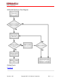
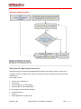
Connection watchdog: This watchdog tests if the active WAN interface is able to connect to the
internet. If not it will trigger the next WAN interface in the priority list.
When it detects that the 3G interface is not able to contact the internet it will trigger the next WAN
interface in the priority list and it will reset or reconnect the WWAN module.
You can find here a flow chart of the feature.
Timed Reset: resets the gateway after a period of time.
Connection Watchdog
Enabled
Set to Yes to enable the connection watchdog and monitor the active WAN interface for data
received.
If no data is received after a certain period of time (= checking interval), the connection watchdog
will:
o
o
o
Try to lookup the URL/IP addresses
If activated, try to ping the URL/IP addresses.
If both actions fail than the next WAN interface in the priority list will be activated. When the
failing WAN interface is the 3G interface than the WWAN module will be reset or try to reestablish a connection.
Addresses to Check
Specifies the IP addresses or URL's to send a DNS request or PING to if the connection watchdog is
enabled
A maximum of 5 IP addresses or URL's can be specified.
Revision: 1.00
Copyright 2015 U.S. Robotics Corporation
44 | P a g e
IMPORTANT: The URLs in the table must be the domain name, not the complete URL.
For example:
www.google.com will be accepted.
http://www.google.com will not work.
I
Use PING in addition to DNS
Sends a PING and DNS request to the specified URL/IP addresses
Checking interval
If no data is received during a time equal to the "checking interval" the connection persistence will
start the URL/IP lookup feature.
Watchdog action
Resets the WWAN module or tries to re-establish the connection to the wireless network. Resetting
the WWAN module can take about 2 minutes, reconnecting to the wireless network will take about
20 seconds.
Timed Reset
The Timed Reset section sets up the device to reset on a daily, weekly or monthly basis.
Enabled
Set to Yes to enable the Timed Reset watchdog. The gateway will reset at the specified time
interval.
Frequency
Set to Daily and select the time of the day at which you want to perform the reset.
Set to Weekly and select the days of the week you want to perform the reset, and the time of day.
Selected days are green.
Revision: 1.00
Copyright 2015 U.S. Robotics Corporation
45 | P a g e
Set to Monthly and enter the day of the month and the time of the day.
Provisioning Tab
The Provisioning tab configures how and when the gateway checks for updates from the USR Universe.
By default, the gateway base unit connects to the USR Universe each time the device is powered on, and
checks for an updated image. The device downloads and installs the update over the WAN interface.
Check for Updates
Check for updates
Checks the USR Universe for firmware, developer image, and configuration file updates
Click the Check for Updates button to check for updates even if Enable automatic provisioning is
disabled.
Upload Device Provisioning File
Select file
Updates the unit with an image from a hard drive.
Click Browse to select the file and then click Upload.
Revision: 1.00
Copyright 2015 U.S. Robotics Corporation
46 | P a g e
Settings
Enable Automatic Provisioning
Controls automatic updates from the USR Universe.
Set to Yes to automatically check for updates. This happens:
o
o
Each time the unit is powered on.
Depending on the "check-in frequency" parameter on the USR Universe.
Set to No to disable automatic provisioning.
System Tab
The System tab configures remote access settings, log file parameters, and manual reset settings.
It includes the following sections:
Time Settings
Power Savings
Data counters
Remote Access
Dynamic DNS
Username and Password
Logging
Config Export
System Reboot and Factory Reset
Revision: 1.00
Copyright 2015 U.S. Robotics Corporation
47 | P a g e
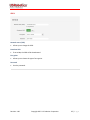
Time Settings
Timezone
Sets the timezone used by the unit for the Timed Reset watchdog.
NTP server
Defines the domain name of an NTP server.
Power Savings
Turn off LEDs
This parameter disables (Yes) or enables (No) the LEDs on the base unit front panel.
Revision: 1.00
Copyright 2015 U.S. Robotics Corporation
48 | P a g e
Data Counters
Reset all data counters
This resets all data counters.
Related Topics
Data Counters
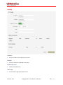
Remote Access through HTTPS
The Remote Access section configures a port on the gateway for remote access. With remote access,
you can log into the embedded web interface from a remote PC or laptop.
To set up remote login:
1. Click the 3G connection tab and make a note of the IP address of the WAN connection displayed
in IP Configuration.
2. Click the System tab.
3. Set the Remote access through HTTPS field to Yes.
4. Enter the port number for which remote login is allowed.
5. Click Save changes.
To log in to the gateway remotely:
1. On a remote laptop, go to the URL: https://IPaddress:portnumber.
2. Enter the user name and password.
Revision: 1.00
Copyright 2015 U.S. Robotics Corporation
49 | P a g e
Dynamic DNS
Enabled
Set to Yes to enable Dynamic DNS.
Service Provider
Selects the dynamic DNS service provider.
Host name
Defines the host name for the DNS service provider account.
User name
Defines the user name you have set up with the DNS service provider.
Password
Defines the password you have set up with the DNS service provider.
Use HTTPS
Set to Yes to enable HTTPS login.
Revision: 1.00
Copyright 2015 U.S. Robotics Corporation
50 | P a g e
Status
Displays status information.
Click Update to refresh the status.
Username and Password
Username
Sets a new username for logging on to the embedded web interface.
Password
Resets the password.
Revision: 1.00
Copyright 2015 U.S. Robotics Corporation
51 | P a g e
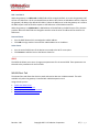
Logging
Customer support may request logfiles to diagnose a problem.
To create a logfile:
1.
2.
3.
4.
5.
Click Yes to enable logging.
Set additional logging parameters according to Customer Support recommendations.
Click Save changes.
Reproduce the gateway problem.
Download the log file by clicking Download log file.
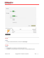
Enable logging
If set to Yes, the unit logs all gateway activity.
Maximum log file size
Sets the maximum log file size. USRobotics recommends 256 kB.
Select log levels
Sets the log levels. In order of severity the levels are: Info, Warning, Error, and Debug.
Download log file
Downloads the file to a hard drive or USB stick.
Clear log file
Removes the log file from the unit's memory.
Revision: 1.00
Copyright 2015 U.S. Robotics Corporation
52 | P a g e
Config Export
Download config
Click to save the device configuration to a file on a laptop. The configuration file can then be
uploaded to the Provisioning Server and used for provisioning multiple devices.
System Reboot and Factory Reset
Two different manual resets are possible on the gateway: system reboot and factory reset.
TIP:
Automatic resets of the WWAN interface are managed by the connection watchdog feature.
Automatic resets of the gateway are managed by the timed reset feature.
System reboot
To reboot the gateway:
1. Click System reboot.
2. In the confirmation dialog box, click Reboot to confirm.
Revision: 1.00
Copyright 2015 U.S. Robotics Corporation
53 | P a g e
NOTE: This is the same as pressing the hardware reset button on the back of the gateway for one
second.
Factory Reset
To reset the gateway to the factory default settings and overwrite all custom configuration changes:
1. Click Factory Reset to restart the device with the original firmware version from the factory.
2. Click Factory reset to confirm.
TIP: This is the same as pressing the hardware reset button on the back of the gateway for more than
five seconds.
Hardware Reset Button
The hardware reset button is located on the unit back panel. Using a pen or small screwdriver, press and
hold:
Hold for one second to perform a normal reset.
Hold for five seconds or more to perform a factory reset.
Revision: 1.00
Copyright 2015 U.S. Robotics Corporation
54 | P a g e
Plugin Tab
The Plugin tab configures the serial port settings and the GPS settings.
It includes the following sections:
Serial Port to TCP local or remote server
Serial port settings
TCP settings
GPS to TCP local or TCP/UDP remote server
GPS report settings
TCP/UDP selection
TCP settings
UDP settings
Serial Port to TCP local or remote server
Enable
This parameter enables (Yes) or disables (No) the serial port and presents the serial port settings
menu.
Revision: 1.00
Copyright 2015 U.S. Robotics Corporation
55 | P a g e
Serial port settings
Baud rate
This parameter selects the serial port baud rate.
Data bits
This parameter selects the number of data bits per character.
Revision: 1.00
Copyright 2015 U.S. Robotics Corporation
56 | P a g e
Stop bits
This parameter selects the number of stop bits per character.
Parity
This parameter selects the type of parity bits per character.
Flow control
This parameter selects the type of flow control used by the serial port.
TCP settings
TCP server is Local/Remote
This parameter configures the TCP server to Local or Remote.
Hostname
This parameter defines the hostname of the Remote TCP server.
Port
This parameter defines the TCP port number.
GPS to TCP local or TCP/UDP remote server
Revision: 1.00
Copyright 2015 U.S. Robotics Corporation
57 | P a g e
Enable
This parameter enables (Yes) or disables (No) GPS reporting and presents the GPS settings menu.
GPS report settings
No fix report interval
Seconds between reports when no GPS fix is available.
Revision: 1.00
Copyright 2015 U.S. Robotics Corporation
58 | P a g e
Fix report interval
Seconds between reports when GPS fix is available but not moving.
Report interval
Seconds between reports when GPS fix is available and moving.
Moving if moved
Number of meters moved between fix or move reports to define as moving.
TCP/UDP settings
TCP/UDP selection
This parameter selects a TCP or UDP session for GPS.
TCP settings
TCP server is Local/Remote
This parameter configures the TCP server to Local or Remote.
Hostname
This parameter defines the hostname of the Remote TCP server.
Port
This parameter defines the TCP port number.
Revision: 1.00
Copyright 2015 U.S. Robotics Corporation
59 | P a g e
UDP settings
Hostmname
This parameter defines the hostname of the Remote UDP server.
Port
This parameter defines the UDP port number.
Configuring the VPN
The VPN tab allows adding and configuring IPSec tunnels. By default the gateway has no IPsec tunnels
preconfigured.
A tunnel can easily be added by clicking the “+ add IPsec Tunnel” button, a window will prompt the user
to enter a name for the new tunnel.
Revision: 1.00
Copyright 2015 U.S. Robotics Corporation
60 | P a g e
When the tunnel is successfully added a new field in the VPN tab will appear for each tunnel that is
added.
Tunnels can be removed in the bottom right corner of the field of each tunnel using the “delete tunnel”
button.
Configuring a Tunnel
3 elements can be configured for each tunnel.
Identity
IKE Settings
IPsec Settings
All fields must be configured for the tunnel to become active.
Identity
The identity section provides the ability to configure:
The basic authentication method: currently only PSK is available
A pre shared key
The interface on which the tunnel should be used. Here the user can select if the tunnel can only be
used on a specific connection type or all connection types
Remote Host
Remote & Local identity: These are optional fields that can used in case the other tunnel endpoint
has configured a local identity. This field may contain an IP or a FQDN (fully qualified domain name)
Revision: 1.00
Copyright 2015 U.S. Robotics Corporation
61 | P a g e
IKE Settings
The Internet Key Exchange is a protocol used to set-up the security associations in the IPsec protocol
suit.
IKE Version: V1,V2
Negotiation Mode (only for IKE V1): Main & Aggressive
IKE Encryption: 3DES, AES128, AES 256
IKE Authentication: MD5, SHA1, SHA256
IKE Key Group: DH1, DH2, DH5, DH14
IKE SA Lifetime: must be a value between 60 - 86400
http://en.wikipedia.org/wiki/Internet_Key_Exchange
IPsec Settings
These fields are used to configure the IPsec tunnel's encryption details.
IPsec Encryption: 3DES, AES128, AES 256
IPsec Authentication: MD5, SHA1, SHA256
IPsec Key Group: DH1, DH2, DH5, DH14
IPsec SA Lifetime: must be a value between 60 - 86400
Revision: 1.00
Copyright 2015 U.S. Robotics Corporation
62 | P a g e
Configuring Expansion Cards
If the gateway is installed with an Option expansion card, the device automatically detects and identifies
the card and displays the appropriate configuration tab in the menu bar.
The additional configuration tabs are:
WLAN Access Point: configures the access point of the WLAN expansion card
Click this tab
To do these tasks
WLAN Access Point
Enable the WLAN access point
Configure the SSID of the WLAN access point
Configure WLAN card IP address information
WLAN Client
Enable the WLAN client
Connect the device to a WLAN network
Disconnect the device from a WLAN network
Configuring the WLAN Card
The WLAN expansion card from Option acts as both a WLAN access point and WLAN client. The WLAN
access point allows the gateway to connect other wireless devices to a wired or 3G network. The WLAN
client allows the gateway to send and receive data over a WLAN network.
To use the WLAN expansion card, first, install the expansion card, and then configure the card by clicking
the following tabs in the menu:
WLAN Access Point
WLAN Client
WLAN Access Point Tab
The WLAN Access Point tab lets you to manage the broadcast settings of the wireless access point. You
can see the tab only when the gateway is installed with the WLAN expansion card.
Revision: 1.00
Copyright 2015 U.S. Robotics Corporation
63 | P a g e
General
Enabled
Enables the WLAN access point
WLAN Mode
Selects a 2.4Ghz or 5GHz access point.
Channel
Selects the WLAN channel on which the access point has to work.
Information: The WLAN channel can only be selected when the WLAN client is disabled. In case the
WLAN client is active, the access point will use the channel used by the WLAN client!
Enable second SSID
Activates a second SSID.
Revision: 1.00
Copyright 2015 U.S. Robotics Corporation
64 | P a g e
SSID 1
Network name (SSID)
Allows you to change the SSID.
Broadcast SSID
If set to Yes, the SSID will be broadcasted.
Encryption
Allows you to choose the type of encryption.
Password
Sets the password.
Revision: 1.00
Copyright 2015 U.S. Robotics Corporation
65 | P a g e
IP Config
IP address
Sets the IP address of the WLAN access point.
Netmask
Sets the netmask of the WLAN access point.
Enable DHCP server
Enables the DHCP server.
DHCP range
Sets the DHCP range for the DHCP server.
Revision: 1.00
Copyright 2015 U.S. Robotics Corporation
66 | P a g e
DNS 1 and DNS 2
When the gateway is in LAN mode the DNS fields will be empty by default. As a result the gateway itself
will act as a DNS server. All the connected Ethernet devices will receive an DNS address which is equal to
the gateway's IP address (by default 192.168.1.1) When the DNS server inside the gateway can't resolve
the DNS request it will forward the request to the DNS server of the WAN connection.
When the gateway is in WAN mode the DNS address will be defined by the DHCP server of the internet
provider. When the DNS fields are changed to another value the other IP address will be used for the
DNS server.
Reserved leases
Lists the DHCP leases which are assigned to a MAC address.
Click Add to assign another lease and link a MAC address to an IP address.
Active leases
Lists the active DHCP leases of the devices connected to the Wi-Fi access point.
Click Reserve to add the lease to the Reserve leases list.
SSID2
The SSID2 tab allows you to set or change some parameters for the second SSID. These parameters are
identical to the parameters for the first SSID.
WLAN Client Tab
The WLAN Client tab allows the device to send and receive data over a WLAN network. The tab is
available only when the gateway is installed with a WLAN expansion card.
Using this tab you can:
Enable the WLAN client
Connect to a WLAN network
Manually Connect to a WLAN network
Disconnect from a WLAN network
Revision: 1.00
Copyright 2015 U.S. Robotics Corporation
67 | P a g e
General
Enabled
Click Yes to enable the WLAN client, and then click Save changes.
IP Config
IP Mode
Click Dynamic to use IP addresses provided by the DHCP server
Click Static to use a fixed IP address. Enter the IP address, netmask and DNS information.
Revision: 1.00
Copyright 2015 U.S. Robotics Corporation
68 | P a g e
IP Config
Displays the IP, netmask and gateway addresses of the connected WLAN network.
Available & Known networks
Lists the WLAN networks within range and displays the signal quality, SSID, status, and encryption
method of each.
Click the Refresh icon to refresh the network list.
Connecting to a WLAN Network
To connect to a WLAN network:
1. Click the network name.
2. Enter the network password and click Connect.
3. Note the status change to connected in the Available & Known Networks list.
Creating a Manual Connection to a WLAN Network
If the WLAN network you want to use is not in the list of known networks, you can create a manual
connection.
Revision: 1.00
Copyright 2015 U.S. Robotics Corporation
69 | P a g e
1. Click Manual connection.
2. Enter the network SSID, select an encryption type and enter the network password.
3. Click Save.
Disconnecting from a WLAN Network
1. Click the Wi-Fi network to disconnect.
2. Click Forget network.
Revision: 1.00
Copyright 2015 U.S. Robotics Corporation
70 | P a g e
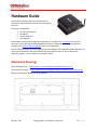
Hardware Guide
The Hardware Guide provides the detailed technical
information and hardware specifications for the gateway
base unit.
This guide is designed for:
Third-party developers
Distributors
System integrators
Field engineers
Details about installing and configuring the gateway are available in the User Guide section of this
document. Information about deploying gateway firmware, configuration and software updates is
available in the Provisioning Server Guide section of this document.
And this Gateway design can be licensed to third party hardware and software developers who want to
create custom expansion cards and software images for specific needs. For information on the
developer program, contact USRobotics Customer Support.
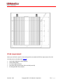
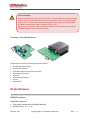
Mechanical Drawings
3D file of the gateway. --> http://support.usr.com/support/3510/files/Gateway_3D.zip
3D file of the front plate --> http://support.usr.com/support/3510/files/Gateway_front_plate_3D.zip
Below you can find the dimensions of the gateway.
Revision: 1.00
Copyright 2015 U.S. Robotics Corporation
71 | P a g e
IP-65 requirement
Below you can find the parts for the encasing which are needed to fulfill the requirements for IP-65.
All these parts can be ordered by TAKACHI:
1x box BACK 203013G or BCPK 203013S,
1x plate BMP 2030P,
1 x screws (20pcs) MT4-8T,
1x bracket (2x4 pcs) BLF-2G(PC-GF) or CK-26P (metal SS)
3x cable gland MG-12S (3 inputs)
Revision: 1.00
Copyright 2015 U.S. Robotics Corporation
72 | P a g e
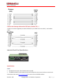
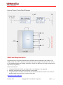
Front and Back Panels
The front and back of the gateway case consist of a top panel and a bottom panel secured with Torx T6
screws.
The top panels cannot be changed. The bottom panels can be customized based on the requirements of
the expansion card.
Revision: 1.00
Copyright 2015 U.S. Robotics Corporation
73 | P a g e
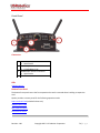
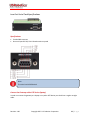
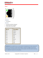
Front Panel
3
1
2
4
Connectors
1
2
3
4
WWAN Diversity antenna connector
SMA-female
Ethernet port
10/100 Mbps RJ-45
WWAN Main antenna connector
SMA-female
Torx T6 screws
LEDs
LED Descriptions
Bottom Front Panel
The bottom front panel covers the front expansion slot and is removed when installing an expansion
card.
Option provides a custom panel for the following expansion cards:
Low Cost Serial Card (Included in base unit)
Industrial Serial Card
Basic Ethernet Switch
PoE Ethernet Switch
Revision: 1.00
Copyright 2015 U.S. Robotics Corporation
74 | P a g e
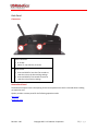
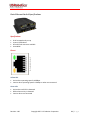
Back Panel
Connectors
1
1
Power connector
2
2
9-33 VDC
Micro-Fit 3.0, dual row, 4 circuits
Reset button
Press and hold for less than five seconds to
reset the unit to the last working settings.
Press and hold for five seconds or more to
reset the unit to factory settings
Bottom Back Panel
The bottom back panel covers the opening for the back expansion slot and is removed when installing
an expansion card.
Option provides a custom panel for the following expansion cards:
Wi-Fi Card
Developer Card
Revision: 1.00
Copyright 2015 U.S. Robotics Corporation
75 | P a g e
LED Descriptions
LED
Description
WLAN State
Indicates the connection status of the WLAN interface
Off: not installed
Orange: Wlan board = OK, client not connected and AP not enabled
Orange blinking: AP disabled and Client connected / data traffic
Red: board error/ (Any that causes AP or Client not to work)
Green: AP enabled
Green flashing: AP enabled and Client connected/data traffic
Indicates the signal strength of the WLAN interface
Off: off or not connected
Orange: moderate signal strength
Red: bad signal strength
Green: good signal strength
Green flashing: n/a
Indicates the GPS operation
Off: off
Orange: on, no fix
Red: error
Green: on, has fix
Green flashing: n/a
Indicates the signal strength of the GPS
Off: no signal
Orange: moderate GPS signal
Red: bad GPS signal
Green: good GPS signal
Green flashing: n/a
Indicates successful power on and device readiness
Off: no power
Orange: booting
Red: error
Green: on
Green flashing: n/a
Indicates WWAN or 3G interface availability and use
Off: no power or not connected
Orange: on, not connected
Red: WWAN error
Green: on, connected
Green flashing: data traffic
Indicates WWAN or 3G interface signal strength
Off: no power or not connected
Red: bad signal strength (< -104dbm)
Orange: moderate signal strength (>= -104dbm & < -94dbm)
Green: good signal strength (>= -94dbm)
WLAN Client Signal Strength
GPS/Aux State
GPS/Aux signal strength
System State
WWAN State
WWAN Signal Strength
Revision: 1.00
Copyright 2015 U.S. Robotics Corporation
76 | P a g e
Main Board Specifications
The gateway is designed with one main board and two additional expansion boards.
Main Board
The main board is identical for each base unit and is designed around a micro-controller which controls
a WWAN module and the Ethernet interface.
Main Board Block Diagram (PDF) --> http://support.usr.com/support/3510/files/m2m_box_im_0_0.pdf
Internal Power Supply
Stable 3.4V power rail
Reverse polarity protection
Over-voltage protection up to 60V
Current limiter at 1.2A
One-time fuse of 2A
Main Board Processor
Freescale i.MX280 @ 450MHz
o
o
o
o
o
64 MB RAM
128 MB Flash memory
GTM68X WWAN module1 m
Ethernet interface
Two expansion board connectors
Primary Expansion Board
The primary expansion board has the following interfaces:
Power supply: V_PWR, 3V4, 3V3
24 MHz clock signal
Master reset signal
High speed USB interface
High speed OTG USB interface
SDIO interface
GPIO signals
Serial interface
Secondary Expansion Board
The secondary expansion board has the following interfaces:
Power supply: V_PWR, 3V4, 3V3
Revision: 1.00
Copyright 2015 U.S. Robotics Corporation
77 | P a g e
24 MHz clock signal
Master reset signal
High speed USB interface
SDIO interface
GPIO signals
Expansion Card Specifications
Wi-Fi Card
Low Cost Serial Card
Industrial Serial Card
Basic Ethernet Switch
PoE Ethernet Switch
Developer Card
Telematics Card
WLAN Card Specifications CG2101
Specifications:
According to 802.11 abgn spec
Simultaneous access point and Client mode
Dual SSID
Up to 10 simultaneous users
Supported encryption: WPA-PSK, WPA2-PSK, mixed WPA/WPA2-PSK
RF Specifications:
The antenna connector on the front panel of the WLAN expansion card is a RP-female connector.
Click here for more RF specifications.
Click here for antenna recommendations.
Revision: 1.00
Copyright 2015 U.S. Robotics Corporation
78 | P a g e
Note: 5GHz WLAN operation
In order to reduce the potential for harmful interference to co-channel mobile satellite
systems, the operation in the 5150-5250MHz band (channels 36 to 48) is restricted to
indoor usage only.
Note: group re-keying
The WLAN client of the gateway connected to a WLAN access point configured with WPA
and group re-keying disabled is currently not supported.
RF EXPOSURE WARNING
A minimum distance of 20cm must be maintained between the user's body and the device
antenna.
Industry Canada radiation exposure statement
This equipment complies with Industry Canada's RSS-102 radiation exposure limits set forth for an
uncontrolled environment. This equipment should be installed and operated with minimum distance
20cm between the radiator & your body.
Under Industry Canada regulations, this radio transmitter may only operate using an antenna of a type
and maximum (or lesser) gain approved for the transmitter by Industry Canada. To reduce potential
radio interference to other users, the antenna type and its gain should be so chosen that the equivalent
isotropically radiated power (e.i.r.p) is not more than necessary for successful communication.
This radio transmitter, IC 2734A-CG2101, has been approved by Industry Canada to operate with the
antenna types listed below with the maximum permissible gain and required antenna impedance for
each antenna type indicated. Antenna types not included in this list, having a gain greater than the
maximum gain indicated for that type, are strictly prohibited for use with this device.
2.4GHz band: 3dBi (50Ω)
5GHz band: 3dBi (50Ω)
Revision: 1.00
Copyright 2015 U.S. Robotics Corporation
79 | P a g e
Low Cost Serial Card Specifications
Specifications:
Female DB9 connector
One serial port RS-232, 921.6 Kbaud maximum speed
Note:
The serial card is DCE device!
Connect the Gateway with a DTE device (laptop)
In order to connect the gateway to a laptop or any other DTE device you should use a regular straight
cable.
Revision: 1.00
Copyright 2015 U.S. Robotics Corporation
80 | P a g e
Gateway
(DCE)
Connect the Gateway with another DCE device (modem, PLC,...)
In order to connect the gateway to another DCE device you should use a cross cable. (= null modem
cable).
Industrial Serial Card Specifications
Specifications:
RS232
One RS-232 serial port, 921.6 Kbaud maximum speed
The RS232 interface on the industrial serial card is identical to the one on the low cost serial card.
Please have a look at this low cost serial card for more info on the RS232 interface.
Revision: 1.00
Copyright 2015 U.S. Robotics Corporation
81 | P a g e
RS485
One 22 KV isolated RS-485 serial port, 921.6 Kbaud maximum speed
Connector: Examples of the connector you should use are:
o
o
Phoenix (MC 1,5/5ST-3,81)
Würth (691361300005)
Termination switch: With this switch you can choose to terminate the RS485 network with a 120
Ohm resistor
Wire selection: This switch allows you to use a 4 wire network or a 2 wire network
You can use the gateway in a 2 wire network as shown below:
You can use the gateway in a 4 wire network as shown below:
Revision: 1.00
Copyright 2015 U.S. Robotics Corporation
82 | P a g e
Note:
By default the TX and RX of the RS485 connection are disabled. So you have to enable them
before you can start using the RS485 port. (You can enable this by using the DE and RE
signals). For a 2 wire interface (=half duplex) you should of course only enable one direction
at the same time.
Below an example of how to do this in your code.
(The example shows how to activate both DE and RE)
#include <stdio.h>
#include <string.h>
#include <fcntl.h>
# include <unistd.h>
#include <sys/ioctl.h>
#include <errno.h>
/**************************************************************************
* Manifest Constants
**************************************************************************/
#ifndef TIOCM_OUT1
#define TIOCM_OUT1 0x2000
#define TIOCM_OUT2 0x4000
#endif
#define TIOCM_RE TIOCM_OUT1
#define TIOCM_DE TIOCM_OUT2
/*************************************************************************/
int main (void)
{
int fd = open("/dev/ttySP4",O_RDWR || O_NONBLOCK);
if (fd < 0) { printf("failed to pen device\n"); return 0; }
int status, err;
/* switch on RS485 TRANSMIT buffer and RECEIVE buffer */
ioctl(fd, TIOCMGET, &status);
status |= (TIOCM_DE | TIOCM_RE);
if ((err = ioctl(fd, TIOCMSET, &status)))
{
printf("ioctl error 0x%x, errno 0x%x, status %x",err, errno, status);
}
close(fd);
return 0;
}
Revision: 1.00
Copyright 2015 U.S. Robotics Corporation
83 | P a g e
Basic Ethernet Switch Specifications
Specifications
RJ-45 receptacle tab on top
4-port 10/100 Base-T
One uSD card connector available
Auto-MDIX
Pinout
Yellow LED:
Active when operating speed is 100Mbps
Inactive when operating speed is 10 Mbps or when not connected
Green LED:
Active when valid link is detected
Blinks when activity is detected
Inactive when not connected
Revision: 1.00
Copyright 2015 U.S. Robotics Corporation
84 | P a g e
IMPORTANT: The auto-MDIX feature is always activated on the gateway. This feature automatically
detects the required cable connection type (straight or crossed), and configures the connection
appropriately, removing the need for crossover cables. In order for auto-MDIX to work correctly,
auto-negotiation (auto speed and auto duplex) must be enabled on both sides of the link. Note that
auto negotiation is always active on the gateway.
PoE Ethernet Switch Specifications
Specifications
RJ-45 receptacle tab on top
4-port 10/100 Base-T
Can function as a 2 ports Class 4 PoE or a 4-port Class 3 PoE
Auto-MDIX
Revision: 1.00
Copyright 2015 U.S. Robotics Corporation
85 | P a g e
Pinout
Yellow LED:
PoE indicator
Green LED:
Active when valid links is detected
Blinks when activity is detected
Inactive when not connected
IMPORTANT: The auto-MDIX feature is always activated on the gateway. This feature automatically
detects the required cable connection type (straight or crossed), and configures the connection
appropriately, removing the need for crossover cables. In order for auto-MDIX to work correctly,
auto-negotiation (auto speed and auto duplex) must be enabled on both sides of the link. Note that
auto negotiation is always active on the gateway.
Revision: 1.00
Copyright 2015 U.S. Robotics Corporation
86 | P a g e
Power Supply
Connector: Examples of the connector you should use are:
o
o
Phoenix (MC 1,5/2ST-3,81)
Würth (691361300002)
Operating voltage: 50 - 57Vdc, typical 56Vdc
Power consumption: The mainboard of the gateway consumes about 10W, the Ethernet board can
consume up to 60W (4x15w or 2 x 30W. So the total power should not exceed 70W.
The POE Ethernet board has an internal one time fuse of 2A
The power plug is delivered together with the PoE Ethernet Switch expansion card. The plug is
visible within the red rectangle in the picture below.
This plug allows you to connect an external power supply to the socket on the PoE expansion card.
IMPORTANT: the polarity of the external power supply is indicated on the metal front plate of the
expansion card.
SAFETY WARNING
When the PoE expansion board is inserted in the gateway, the gateway must be powered
from the PoE power supply. The main power input on the back of the gateway will be
disabled!
SAFETY WARNING
The PoE power supply operates on DC power provided via a DC power supply or AC
power adapters. Only use power supplies rated at 56Vdc and make sure the product is
installed near a power outlet that is easily accessible. This product is regarded a class III
equipment where protection against electric shock is provided by means of power
supplied from a SELV (Safety Extra Low Voltage) circuit and does not generate hazardous
voltages within itself.
Revision: 1.00
Copyright 2015 U.S. Robotics Corporation
87 | P a g e
SAFETY WARNING
When using the PoE board at a power level lower or equal to 30W the temperature range
in which you can use this board is equal to the temperature range of the gateway itself (30°C to +70°C). However when the PoE board operates at a power level between 30W
and 60W the temperature range is limited to -30°C to +45°C.
When using an AC adapter make sure that the ambient temperature doesn’t exceed the
specified temperature limits of the AC adapter.
of
Developer Card Specifications
The Developer card has the following functions available.
One RS232 interface (8 pin)
One SD card interface
Two USB interfaces (one normal, one OTG)
One temperature sensor
One relay
One analog input signal
I2C bus
Optocoupler
RF Specifications
WWAN Interface
Supported Frequencies
GSM, GPRS, and Edge bands: 850/900/1800/1900
WCDMA bands: I, II, IV, V, VIII
Revision: 1.00
Copyright 2015 U.S. Robotics Corporation
88 | P a g e
CDMA bands: BC0,1
Output Power
Power Class 4 (2W, 33dBm) for GSM, GPRS 850/900 MHz bands
Power Class 1 (1W, 30dBm) for GSM, GPRS 1800/1900 MHz bands
Power Class E2 (0.5W, 27dBm) for Edge 850/900MHz bands
Power Class E2 (0.4W, 26dBm) for Edge 1800/1900 MHz bands
Power Class 3 (0.25W, 24dBm) for UMTS 850/900/1900/2100 MHz bands
Antenna Interfaces
Main WWAN Antenna
The main antenna is labelled WWAN Main on the front panel. Learn about antenna recommendations.
Connectors
The RF connector on the Gateway is SMA female.
The antenna itself or the connector to the antenna should be SMA male.
Frequency Range
Allows all frequency bands which the integrator wants to use
Performance
Radiation pattern: Omni-directional
Efficiency over all used frequencies: > 50%
Maximum VSWR: < 2.5:1 with 50 ohm reference impedance
Polarization
Linear
Revision: 1.00
Copyright 2015 U.S. Robotics Corporation
89 | P a g e
RF EXPOSURE WARNING
To comply with FCC and Industry Canada regulations limiting both maximum RF output
and human exposure to RF radiation, maximum antenna gain must not exceed:
Cellular (800MHz) band < 4 dBi
PCS (1900MHz) band < 3.5 dBi
AWS (1700MHz) band < 3.5 dBi
To comply with the CE regulations, maximum antenna gain must not exceed the antenna
gain of the Taoglas TG.09.0113 antenna.
Diversity WWAN Antenna
The diversity antenna is labelled WWAN Div GPS on the front panel. Learn about antenna
recommendations.
IMPORTANT: The diversity antenna is by default disabled (from firmware version 1.9.0 onwards).
Learn how to enable the diversity antenna.
Connectors
Uses the same type of connector as the main WWAN antenna
Frequency range
Receive diversity only works on WCDMA and CDMA bands
Only WCDMA and CDMA bands have to be supported by the diversity antenna.
The GPS frequency must also be supported if GPS functionality is desired on the gateway.
Efficiency
Radiation pattern: Omni-directional
Efficiency over all used frequencies: > 25%
Maximum VSWR: < 2.5:1 with 50 ohm reference impedance
Polarization
Linear
Mutual coupling (main antenna and diversity antenna)
Isolation: > 8dB
Envelope correlation coefficient: < 0.5
GPS Antenna
The gateway only supports passive GPS antennas. There is no power supply for active antennas on the
RF connector. For accurate GPS operation make sure the GPS antenna has a clear view of the sky.
Revision: 1.00
Copyright 2015 U.S. Robotics Corporation
90 | P a g e
Maximum VSWR
< 2.5:1 with 50 ohm reference impedance
Polarization
RHCP antenna or a vertical polarized antenna
Frequency range
Frequency range for GPS: 1575.42MHz ± 1MHz
Efficiency
Efficiency: > 50%.
WLAN interface
The WLAN antenna is labelled WLAN Main on the bottom back panel. Learn about antenna
recommendations.
For the Wi-Fi expansion card the following parameters are required for the antenna:
Connector
The RF connector on the Wi-Fi expansion card is an RP-SMA female connector
The RF connector on the Wi-Fi antenna should be an RP-SMA male connector
Frequency range
2.4 Ghz
5 Ghz
The integrator should only choose the frequencies he would like to use.
Performance
Radiation pattern: Omni-directional
Efficiency over all used frequencies: > 50%
Maximum VSWR: < 2.5:1 with 50 ohm reference impedance
Polarization
Linear
Revision: 1.00
Copyright 2015 U.S. Robotics Corporation
91 | P a g e
RF EXPOSURE WARNING
To comply with CE, FCC and IC regulations limiting both maximum RF output and human
exposure to RF radiation, maximum antenna gain must not exceed 3 dBi.
Antenna Recommendations
A number of good antennas are available on the market for use with the gateway. Below is a list of
antennas which can be used as a reference for each functionality.
All antennas listed below are made by Taoglas and are available via DigiKey
Main WWAN Antenna
Taoglas TG.09.0113
Recommended as the standard Main and Diversity antennas
Recommended for all bands except GPS
Diversity and GPS Antenna
There are two recommended options for the Diversity and GPS Antenna.
Option A
Taoglas TG.30.8113
Recommended for all bands including GPS
Can be used as main antenna but very large
Revision: 1.00
Copyright 2015 U.S. Robotics Corporation
92 | P a g e
Option B
Taoglas TG.10.0113
Not recommended for the main antenna (marginal low band performance)
Recommended for high band diversity antenna
Acceptable as low band (700-800-850-900MHz) Diversity antenna
Recommended for GPS antenna
WLAN Antenna
Taoglas GW.59.3153
Recommended for both 2.4 Ghz and 5 Ghz bands
Related Topics
RF Specifications
3G Connection Tab
Ethernet Specifications
Ethernet Interface
RJ-45 receptacle tab on top
10/100 Mbps
100BASE-TX
Auto-MDIX
Revision: 1.00
Copyright 2015 U.S. Robotics Corporation
93 | P a g e
Pinout
Yellow LED:
Active when operating speed is 100Mbps
Inactive when operating speed is 10 Mbps or when not connected
Green LED:
Active when valid links are detected
Blinks when activity is detected
Inactive when not connected
IMPORTANT: The auto-MDIX feature is always activated on the gateway. This feature automatically
detects the required cable connection type (straight or crossed), and configures the connection
appropriately, removing the need for crossover cables. In order for auto-MDIX to work correctly,
auto-negotiation (auto speed and auto duplex) must be enabled on both sides of the link. Note that
auto negotiation is always active on the gateway.
Revision: 1.00
Copyright 2015 U.S. Robotics Corporation
94 | P a g e
WAN/LAN Switchover Feature
The WAN/LAN switchover feature defines the state of the Ethernet port at power-on. By default, this
feature is enabled. Learn how to disable WAN/LAN Switchover.
Two modes are possible:
WAN mode: the Ethernet interface act as a WAN interface
LAN mode: the Ethernet interface acts as a LAN interface
Each time the unit is powered on:
Gateway sends a DHCP discover message over the Ethernet interface.
When it receives a DHCP offer it proceeds with the DHCP protocol and the Ethernet interface
remains in WAN state.
When it does not receive a DHCP offer it resends the DHCP discover message five times. If no DHCP
offer is received after five tries, the gateway starts running a DHCP server on the Ethernet interface
and act as a LAN interface.
TIP: WAN/LAN detection only happens during power on. The Ethernet connection remains in the same
state (WAN or LAN) until a power cycle or reset has happened.
Revision: 1.00
Copyright 2015 U.S. Robotics Corporation
95 | P a g e
WAN/LAN Switchover Flow Diagram
Related Topics
Ethernet Tab
Revision: 1.00
Copyright 2015 U.S. Robotics Corporation
96 | P a g e
Environmental Specifications
Operating temperature: -30°C to 70°C
Storage temperature: -40°C to 85°C
Humidity operational: 5% - 95% non condensing
Power Requirements
Base Unit Power Supply
Input voltage must be between 9V - 33V DC
Internal electronic fuse limits the input current to 1.2A
USRobotics recommends to use a wire between the gateway and the external power supply of 22
AWG!
SAFETY WARNING
This device operates on DC power provided via a DC power supply or AC power adapters.
Only use power supplies in the range 9-33V DC and make sure the product is installed
near a power outlet that is easily accessible. This product is regarded a class III equipment
where protection against electric shock is provided by means of power supplied from a
SELV (Safety Extra Voltage) circuit and does not generate hazardous voltages within itself.
SAFETY WARNING
When using an AC adapter make sure that the ambient temperature doesn’t exceed the
specified temperature limits of the AC adapter.
As a reference, the power supply available from USRobotics has the following parameters:
Output voltage 12V DC
Max output current 1A
If an industrial power supply is preferred USRobotics recommends:
http://www.us.tdk-lambda.com/ftp/Specs/dspa.pdf
It can be sourced through Farnel, Mouser, digikey, ...
Revision: 1.00
Copyright 2015 U.S. Robotics Corporation
97 | P a g e
Power Connector
The power connector is a Micro-Fit connector from Molex (MX-43025-0400).
Power Connector Drawing (PDF) --> http://support.usr.com/support/3510/files/molex_43025400_drawing.pdf
Power Connector Datasheet (PDF) --> http://support.usr.com/support/3510/files/molex_43025400_datasheet.pdf
Pinout
Internal Power Circuits
The voltage applied by the power adapter to the gateway is converted into different voltage levels by
the main board. Two different power circuits make five different voltage rails.
Dedicated high current power circuit
Provides two different voltage rails which both can deliver high current levels:
Revision: 1.00
Copyright 2015 U.S. Robotics Corporation
98 | P a g e
o
o
V_PWR: Is the voltage level of the power adapter limited to 1.2A. A little voltage drop lower
than 1V will be caused by the protection circuit.
3V4: A 3.4V power rail made by a dedicated power circuit which is used on the main board but
also accessible by the expansion boards
Low power circuit generated by the micro controller
Provides three voltage rails for very limited power:
o
o
o
3V3: A 3.3V power rail provided by the micro controller is used on the mainboard but also
accessible to the expansion boards
1V8: A 1.8V power rail provided by the micro controller and only used on the main board
1V2: A 1.2V power rail provided by the micro controller and only used on the main board
Voltage Rail
Voltage
Usage
Max Current
V_PWR
Equals the
applied voltage
of the power
adapter
Use for power-hungry
devices
Current is limited to 1.2A
3V4
3.4V
Powers all standard digital
components on the
expansion cards
3A maximum of which the
main board is already using
1.5A. Only 1.5A is left for
both expansion cards. (The
sum of both expansion
cards should be lower than
1.5A)
3V3
3.3V
Powers low power
components or level
translators from I/O signals
on expansion connectors
towards other components
used the expansion cards
Powers low power
components or level
translators from I/O signals
on expansion connectors
towards other components
used the expansion cards
1V8
1.8V
Internal use only
Internal use only
1V2
1.2V
Internal use only
Internal use only
Revision: 1.00
Copyright 2015 U.S. Robotics Corporation
99 | P a g e
Internal Power Circuits Block Diagram
SIM Card Requirements
The gateway has an integrated (U)SIM interface compatible with the ISO7816 IC card standard. The
3GPP standard defines three operational voltages for the supply voltage of the SIM card: 1.8V, 3V and
5V. The gateway supports two voltages: 1.8V and 3V. The 5V-only SIM cards are rarely used and are not
supported by the gateway.
General requirements:
Changing of SIM cards while in operating mode, or hot-swapping, is not supported.
Detection of the SIM card removal can take up to 30 seconds.
The gateway will not be able to communicate with the SIM card after re-insertion. As a result, the
gateway needs to be reset after re-insertion of the SIM.
Learn how to install a SIM card.
Revision: 1.00
Copyright 2015 U.S. Robotics Corporation
100 | P a g e
Certification and Operator Approvals
For detailed info about the obtained regulatory certification and operator approvals, please select your
gateway product:
USR3510 3G Americas
USR803510 3G EMEA
Safety warnings
Please read the following guidelines carefully. Not following these guidelines can cause harm to
the gateway, yourself or other persons.
RF EXPOSURE WARNING
A minimum distance of 20cm must be maintained between the user's body and the
device antennas.
General recommendations for use
do not open your product when powered.
do not expose to liquid, moisture or humidity.
do not drop, throw or try to bend your product.
do not paint your product.
do not touch the antenna unnecessarily.
Ambient temperatures
Do not operate your product at ambient temperatures beyond the range of -30 and +70 degrees Celsius
(exception: PoE functionality is limited to 45°C when using more than 30W). When using an AC adapter
make sure that the ambient temperature doesn’t exceed the specified temperature limits of the AC
adapter.
In restricted areas, such as dedicated equipment rooms or electrical closets, where the temperature can
exceed 65°C, the temperature of the surface might reach high values and therefore under these
conditions the products need to be protected against accidental contact. We recommend that operators
who plan to use this product at these high temperatures stick a warning sticker, in accordance with IEC
60417-5041 (DB:2002-10), on a visible part of the device, or attach a sticker with the following text:
WARNING
HOT SURFACE
DO NOT TOUCH
Revision: 1.00
Copyright 2015 U.S. Robotics Corporation
101 | P a g e
Explosive atmosphere
Turn off your device in any area with a potentially explosive atmosphere. It is rare, but your device could
generate sparks, which could cause an explosion or fire. Areas with a potentially explosive atmosphere
are not always clearly marked. They include fueling areas (petrol filling stations), below deck on boats,
fuel or chemical transfer or storage facilities and areas where the air contains chemicals or particles,
such as grain, dust, or metal powders. Do not transport or store your product in the compartment of a
vehicle which contains flammable gas, liquid or explosives.
Blasting areas – construction sites
Turn off your product when in a blasting area in order to avoid interfering with two-way radios used in
blasting operations.
Do not use on aircraft
Using a wireless devices on aircraft can cause interference. Do not use it when the plane is on the
ground without permission from the aircraft crew.
Driving
Do not operate your device while driving. Park the vehicle first.
Medical equipment
Do not use near medical equipment, especially life support equipment that might be susceptible to radio
interference.
ESD notice
Electrostatic Discharge (ESD) is caused by a buildup of static electricity and can happen when making
contact with a product. To limit the likelihood of Electrostatic Discharge, it is recommended to:
avoid conditions that result in high static electricity (carpet, cool and dry air,…);
avoid touching any connectors when handling the unit; only touch the casing if possible;
ground yourself prior to handling by touching a large metal object.
In case the product encounters loss of performance after an Electrostatic Discharge, please reset the
device in order to restore it to normal functionality.
Class A device
This is a class A product. In a domestic environment this product may cause radio interference in which
case the user may be required to take adequate measures. The operation of the gateway is restricted for
use in a commercial, industrial or business environment.
Manufacturer's disclaimer statement
The information in this document is subject to change without notice and does not represent a
commitment on the part of the vendor. No warranty or representation, either expressed or implied, is
made with respect to the quality, accuracy, or fitness for any particular purpose of this document. The
Revision: 1.00
Copyright 2015 U.S. Robotics Corporation
102 | P a g e
manufacturer reserves the right to make changes to the content of this document and/or the products
associated with it at any time without obligation to notify any person or organization of such changes.
In no event will the manufacturer be liable for direct, indirect, special, incidental, or consequential
damages arising out of the use or inability to use this product or documentation, even if advised of the
possibility of such damages.
For questions regarding your product or declaration, contact:
U.S. Robotics Corporation
1300 East Woodfield Road, Suite 506
Schaumburg, IL, 60173
U.S.A.
http://www.usr.com/
To identify this product we refer to the Part, Series, or Model number found on the product.
USR3510 3G Americas
FCC
This device complies with the applicable FCC rule parts. The FCC approval is valid for the USR3510 3G
Americas and the following expansion cards:
model: CG1101, the Low cost serial card;
model: CG1102, the Industrial serial card;
model: CG1103, the Ethernet switch with PoE;
model: CG1104, the Ethernet switch;
model: CG1106, the Telematics base board;
model: CG2101, the WLAN expansion card;
model: CG3101, the Telematics I/O expander.
Industry Canada
This device complies with the applicable IC rules. The IC approval is valid for the USR3510 3G Americas
and the following expansion cards:
model: CG1101, the Low cost serial card;
model: CG1102, the Industrial serial card;
model: CG1103, the Ethernet switch with PoE;
model: CG1104, the Ethernet switch;
model: CG1106, the Telematics base board;
model: CG2101, the WLAN expansion card;
model: CG3101, the Telematics I/O expander.
PTCRB
The USR3510 3G Americas is PTCRB certified. PTCRB certification is only needed for the basic
configuration, not for the expansion cards.
Revision: 1.00
Copyright 2015 U.S. Robotics Corporation
103 | P a g e
Operator approvals
The USR3510 3G Americas is approved by the following network operators:
Aeris
AT&T
Bell Mobility
Sprint
T-Mobile
Telus
Verizon Wireless
Regulatory information
This device complies with Part 15 of the FCC rules and with Industry Canada license-exempt RSS
standards. Operation is subject to the following two conditions:
(1) this device may not cause harmful interference, and
(2) this device must accept any interference received, including interference that may cause undesired
operation.
Federal communications commission notice
This equipment has been tested and found to comply with the limits for a Class A digital device,
pursuant to part 15 of the FCC Rules. These limits are designed to provide reasonable protection against
harmful interference when the equipment is operated in a commercial environment. This equipment
generates, uses, and can radiate radio frequency energy and, if not installed and used in accordance
with the instruction manual, may cause harmful interference to radio communications. Operation of this
equipment in a residential area is likely to cause harmful interference in which case the user will be
required to correct the interference at his own expense.
Exposure Information to Radio Frequency Energy
Users concerned with the risk of Radio Frequency exposure may wish to limit the duration of their calls
and to position the antenna as far away from the body as is practical.
Modifications
Any changes or modifications made to this device that are not expressly approved by USRobotics could
void the user's authority to operate the equipment.
USR803510 3G EMEA
CE
This device complies with the essential requirements of the R&TTE directive (1999/5/EC) issued by the
Commission of the European Union.
The USR803510 3G EMEA is certified together with the following expansion cards:
model CG1101, the Low cost serial card;
Revision: 1.00
Copyright 2015 U.S. Robotics Corporation
104 | P a g e
model CG1102, the Industrial serial card;
model CG1103, the Ethernet switch with PoE;
model CG1104, the Ethernet switch;
model CG1106, the Telematics base board;
model CG2101, the WLAN expansion card;
model CG3101, the Telematics I/O expander.
The R&TTE declaration of conformity can be downloaded at the bottom of this page.
E-mark
The USR803510 3G EMEA is complying with the Automotive EMC requirements according to regulation
UN ECE-R10 revision 4 and EU Automotive EMC directive 2004/104/EC.
The USR803510 3G EMEA is certified together with the following expansion card:
model CG2101, the WLAN expansion card.
Waste from Electrical and Electronic Equipment (WEEE)
Attention: Your product is marked with this symbol. Electrical and electronic equipment should not be
disposed of with general household waste. There is a separate collection system for these items.
Please contact your supplier for information on their disposal policy. You may be charged for the costs
of take-back and recycling. In some countries, small products in small quantities may be disposed of at
designated collection facilities. Please contact your local authority for details.
CE Declaration of Conformity (R&TTE) --> http://support.usr.com/support/3510/files/803510-doc.pdf
Certification of third-party expansion cards
Option offers third-party hardware developers the possibility to design their own expansion cards for
the Gateway. The Gateway and the Option expansion cards are compliant with the necessary regulatory
requirements, but third-party hardware developers should still make sure the final product remains
compliant when inserting their expansion cards into the Gateway. Before placing these tailor made
expansion cards in the market, it’s the hardware developer's task to evaluate its expansion card for
continued compliance. This page aims to give some initial guidance on the amount of certification that is
needed.
The regulatory requirements for expansion cards are typically concerned with the correct use of the
radio spectrum, EMC, safety and health regulations. They check if the product is working according to RF
regulations and is safe for use; for example, no unwanted emissions, not too high power emissions, the
effective use of RF spectrum, etc. Finally, also correct labeling and information to the end user is
needed.
Revision: 1.00
Copyright 2015 U.S. Robotics Corporation
105 | P a g e
The amount of testing and certification work highly depends on the supported functionality. Digital
devices containing no wireless transmitter can still transmit unwanted emissions (unintentional
radiators) which can interference with other devices. Devices containing a wireless transmitter should
make sure their RF behavior is within specification and meets safe limits for people.
The most common regulatory approvals are described now.
Federal Communications Commission (FCC)
When selling/operating you own expansion card in the USA, it shall comply with the rules of the Federal
Communications Commission. When the expansion card contains a wireless transmitter, more testing
will be need than when the expansion card doesn’t have a wireless transmitter.
Expansion card without wireless transmitter
Even when a digital device contains no wireless transmitter, it can still emit RF noise and cause
interference to other digital devices. To tackle this, the FCC has imposed rules for these “unintentional
radiators”. The FCC requirements can be found in FCC Part 15, subpart B “unintentional radiators”.
Depending on the type of Part 15B device, a different equipment authorization procedure is required.
Most expansion cards will fall in the category "Class A digital devices, peripherals & external switching
power supplies” and will be subject to the "Verification" method. This means testing the conducted and
radiated emissions and keeping the test results on record, while no FCC logo or FCC ID is needed.
These FCC Part15, subpart B tests can be executed in authorized test labs.
Expansion card with wireless transmitters
Expansion cards with wireless transmitters shall still comply with the requirements for the nontransmitting parts explained above. In addition one should check the requirements for the specific
frequency of the transmitter. Typically tests are required for RF output power, modulation
characteristics, occupied bandwidth, frequency stability and radiated spurious emissions. In addition the
expansion card will mostly be required to carry its own FCC ID.
When the expansion card makes use of an already certified radio module, the test results might be fully
or partially re-used and there's no need for a new FCC ID.
The FCC differentiates between licensed and unlicensed transmitters.
licensed transmitters: devices operating in a frequency that is licensed by the FCC (e.g. PCS
1900MHz or cellular 850MHz). The FCC strictly controls interference in these bands!
unlicensed transmitters: devices operating in unlicensed frequency bands. Different technologies
can be used in these frequency bands and interference restrictions are less severe (e.g. 2.4GHz
WLAN, Bluetooth, ZigBee…).
Technical standards for licensed and unlicensed equipment are found in the various radio service rule
parts. Depending on the specifications of your expansion card, testing is needed for the applicable rule
part(s). Some common rule parts include:
FCC Part 15C for Intentional Radiators (2.4GHz band);
FCC Part 15E for UNII devices (5GHz band);
FCC Part 24 Personal communications services (1900MHz band);
...
Revision: 1.00
Copyright 2015 U.S. Robotics Corporation
106 | P a g e
Please visit the FCC website for more detailed info on the equipment authorization procedures and the
different FCC rule parts.
These FCC tests can be executed in authorized test labs.
Industry Canada (IC)
When you want to sell/use your expansion card in both Canada and USA, it is advised to do the IC and
FCC testing together. Typically the same testing can be performed, resulting in reduced testing costs.
Expansion card without wireless transmitter
Digital devices without transmitter are typically categorized as "interference causing equipment". These
devices shall comply with ICES-003 requirements for Digital Apparatus and are approved through the
method of Self-Declaration of Compliance (SDoC). Similar as FCC Part 15B devices, compliance is
checked for conducted and radiated emissions. When compliant with the limits, the product shall carry a
compliance label stating “CAN ICES-3 (A)/NMB-3 (A)” for a typical Class A device.
These ICES-003 tests can be executed in authorized test labs.
Expansion card with wireless transmitters
Expansion cards with wireless transmitters shall still comply with the requirements for the nontransmitting parts explained above. In addition one should check the requirements for the specific
frequency of the transmitter. Typically tests are required for RF output power, modulation
characteristics, occupied bandwidth, frequency stability and spurious emissions. In addition the
expansion card might be required to carry the IC ID.
When the expansion card makes use of an already certified radio module, the test results might be fully
or partially re-used.
Similar as for FCC, Industry Canada differentiates between licensed and unlicensed ("license-exempt")
transmitters. Depending on the specifications of your expansion card, testing is needed for the
applicable standard(s). The technical standards for licensed and unlicensed equipment are found in the
various Radio Standards Specifications:
RSS-210 for License-exempt radio apparatus (2.4GHz, 5GHz,…);
RSS-132 for cellular telephone systems (850MHz);
RSS-133 for 2GHz personal communication services (1900MHz);
…
Please visit the Industry Canada website for more info on the radio equipment certification procedures
and Industry Canada's standards page.
These IC tests can be executed in authorized test labs.
CE
Before selling/operating a device In the European Union it needs to be compliant with all the applicable
directives and regulations. The most common are:
R&TTE directive;
Automotive EMC directive;
RoHS directive;
Revision: 1.00
Copyright 2015 U.S. Robotics Corporation
107 | P a g e
REACH regulation;
When developing a new expansion card one should make sure the full device is still compliant.
For the R&TTE directive, this means evaluating the product according to the applicable standards related
to EMC emissions, EMC immunity (ESD, surge,...), radio spectrum, RF exposure and product safety. Some
typical standards include:
EN 301489 and/or EN 55022/55024 for EMC emissions and immunity (ESD,…);
EN 60950-1 for ITE safety;
EN 300 328 for 2.4GHz devices;
EN 301 893 for 5GHz devices;
EN 62311 for RF exposure;
When compliance is demonstrated a Declaration of Conformity shall be written to declare the product is
compliant with the R&TTE directive (and some other CE directives). The use of a Notified Body is
optional, but might be useful to check what amount of testing is needed. In that case the Notified
Body number shall be added behind the CE mark.
Please visit the European Commission website for more details on the different EU directives and
regulations.
The info on this page is for information purpose only. Other certification might be needed and
actual certification requirements might differ from the information on this page. It's the actual
responsibility of the third-party hardware developer, to make sure the product complies with the
applicable regulatory requirements.
Revision: 1.00
Copyright 2015 U.S. Robotics Corporation
108 | P a g e
USR Universe Guide
The USR Universe Guide explains how to deploy firmware, configuration, and developer images to
multiple devices.
This guide is designed for:
Distributors
System integrators
Developers
Field engineers
Information about installing and configuring the Gateway is available in the User Guide section of this
document. Details about Gateway hardware specifications and technical information are available in the
Hardware Guide section of this document.
And this Gateway design can be licensed to third party hardware and software developers who want to
create custom expansion cards and software images for specific needs. For information on the
developer program, contact USRobotics Customer Support.
Introducing the USR Universe
The USR Universe is the configuration and deployment mechanism for the Gateway. From the factory,
the Gateway base units have no customization.
On power-up, the Gateway connects to the USR Universe over the wired Ethernet port and
automatically downloads the appropriate update. If the Ethernet interface is unavailable, then the
Gateway uses the WWAN interface to download the updates.
Tip: You can set the USR Universe to enable or disable the automatic downloads.
The Gateway can download the following files from the USR Universe:
Gateway firmware: System firmware provided by USRobotics.
Gateway radio firmware image: software that updates changes to wireless operator firmware
Gateway config file: configuration settings that can be applied to one or more Gateways
Gateway application: customized software that provides additional functionality to the device or
controls third-party expansion cards.
Creating an Account
The following steps are needed for creating an account:
Revision: 1.00
Copyright 2015 U.S. Robotics Corporation
109 | P a g e
1. Visit the page: http://www.usr.com/activate/3510 and click the ‘Green’ button…Sign up now!
2. Enter the required fields and click Sign up >
Revision: 1.00
Copyright 2015 U.S. Robotics Corporation
110 | P a g e
3. If everything is accepted by the validation, a confirmation box will appear that an email has been
sent and you need to open your email account to validate your email address.
4. Click the email link and your browser will open and direct you to USR Universe.
5. You are now signed in and can start to use USR Universe!
Signing In
To Sign in to USR Universe:
1. In a web browser, enter the URL: http://www.usr.com/activate/3510.
2. Enter your email and password and click the 'Blue' button...Sign in >
Click Forgot your password? and follow the instructions to reset your password.
Click Sign up now! to create an account.
Revision: 1.00
Copyright 2015 U.S. Robotics Corporation
111 | P a g e
Activating a Gateway Using USR Universe
Before being able to activate a device, you need to have already created a group (including
correct device type).
You can activate a Gateway two ways:
1. Activate a single device
2. Activate devices in bulk
Activation of a single device
From the ‘Device’ section please click the ‘Activate new device’.
Then fill in the Serial and activation code for this device and choose which group it should
belong to (mandatory). It is also possible to add a friendly name for the device (optional). If no
name is chosen the serial number will be used.
When the Gateway device is powered up, it will check-in to USR Universe. USR Universe will
then enable this device and it will be activated and visible in the group view.
The Gateway will download the group setting (or custom setting), if they differ from what is
currently deployed.
Revision: 1.00
Copyright 2015 U.S. Robotics Corporation
112 | P a g e
Activation of devices in bulk
It is only possible to use the Bulk Device activation when all the devices being activated are the
exact same device type and being added to the same group.
From the ‘Device’ section please click the ‘Activate new device’.
Then click the tab ‘Bulk Device Activation’
Then fill in the Serial and activation code (separated with a comma) for the devices to be
activated - 1 device per line. It is also possible to add a name per device (optional) if added after
each activation code. If no name is chosen the serial number will be used.
Then choose the Group they should be added to (needs to be the same device type)
When the Gateway devices are power up, it will check-in to USR Universe. USR Universe will
then enable these devices and it will be activate and visible in the group view.
The Gateways will download the group setting (or custom setting), if they differ from what is
currently deployed.
Revision: 1.00
Copyright 2015 U.S. Robotics Corporation
113 | P a g e
Groups
The main purpose of a group is that a user can provision (Over-the-Air) the exact same settings/software
to a number of devices, while the devices are out in the field.
A Gateway device must always be inside a group, but can ONLY belong to 1 group
A Gateway hardware device is owned by the group (and not a person)
Only the same device type can be inside 1 group.
Add a group
To add a new group, click the 'Add Group' button within the Device section.
You will then see the following screen:
Fill in the ‘Name’ of the Group, Device Type and a ‘Description’ (optional) of the Group.
This new group will then be visible in the ‘Group’ overview
The user who created the group, becomes by default an ‘Owner’
Revision: 1.00
Copyright 2015 U.S. Robotics Corporation
114 | P a g e
The user can then start to edit the group, adding devices, invite owners and members
Adding device(s) to a group
There are 3 possible ways to add a device or devices to a group:
1. Activate a single device
2. Activate devices in bulk
3. Move from another group
Adding a single device
From the ‘Device’ section please click the ‘Activate new device’.
Then fill in the Serial and activation code for this device and choose which group it should
belong to (mandatory). Also possible to add a friendly name for the device (optional). If no name
is chosen the serial number will be used.
When the Gateway device is powered up, it will check-in to USR Universe. USR Universe will
then enable this device and it will be activated and visible in the group view.
Revision: 1.00
Copyright 2015 U.S. Robotics Corporation
115 | P a g e
Adding devices in bulk
It is only possible to use the Bulk Device activation when all the devices being activated are the
exact same device type and being added to the same group.
From the ‘Device’ section please click the ‘Activate new device’.
Then click the tab ‘Bulk Device Activation’
Then fill in the Serial and activation code (separated with a comma) for the devices to be
activated - 1 device per line. It is also possible to add a name per device (optional) if added after
each activation code. If no name is chosen the serial number will be used.
Then choose the Group they should be added to (needs to be the same device type)
When the Gateway devices are powered-up, it will check-in to USR Universe. USR Universe will
then enable these devices and they will be activated and visible in the group view.
Revision: 1.00
Copyright 2015 U.S. Robotics Corporation
116 | P a g e
Moving a device from another group
Go to 'Devices/Group/Manage devices', then check the device(s) you want to move and click
'Change group'
Then choose the destination group and confirm the changes.
Move a device to another group
If you want to move a device to another group, the following needs to be in place:
You need to be an ‘Owner’ of both groups…both for the group you are moving the device from
and for the destination group
Device type needs to be the same for both groups
To move a device to another group:
1. Go to 'Devices/Group/Manage devices', then check the device(s) you want to move and click
'Change group'
2. Then choose the destination group and confirm the changes.
3. Next time the device(s) checks-in, it will download the group software settings
It is also possible to move a device to another group from a device detail page. Click the
'Edit device' button and follow the steps 2 & 3 as mentioned above.
Note: If this device had a custom setup in the previous group, when moving the device, the custom
setup will disappear and follow the new group settings (unless you choose to make this device
custom again after moving the device)
Edit Group Name and Description
You can always edit the group name or description for your groups.
Revision: 1.00
Copyright 2015 U.S. Robotics Corporation
117 | P a g e
To change the group name and description:
1. Click Devices in the menu.
2. Select the group you want to edit.
3. In the group overview, select 'Edit group'.
4. Enter your changes and click 'Update'
Note: This action can also done per device using the device detail page
Revision: 1.00
Copyright 2015 U.S. Robotics Corporation
118 | P a g e
Setting the Check-in Frequency
The check-in frequency is the interval at which a device connects to the USR Universe and checks for
updates.
To set the check-in frequency:
1. Click Devices in the menu.
2. Select the group you want the change the check-in frequency.
3. In the group overview, select 'Edit group'.
4. Choose the desired Check-in frequency and click 'Update'.
Revision: 1.00
Copyright 2015 U.S. Robotics Corporation
119 | P a g e
IMPORTANT USRobotics recommends caution when setting the check-in frequency to NEVER. If
NEVER is selected, the next time the device connects to the USR Universe, the automatic check-in
function will be turned off permanently. Even if the check-in frequency is changed later, the device
will not connect with the USR Universe and download the new setting.
All the devices in this group will be updated with the new check-in frequency next time the devices
check-in.
Note: This action can also be done per device using the device detail page.
Displaying Group Software
To display the software assigned to a group:
1. Click Devices in the menu and select the group.
Revision: 1.00
Copyright 2015 U.S. Robotics Corporation
120 | P a g e
2. In the 'Software section' you will see the current software set for this group.
To change the group software settings, click the 'Manage software' button.
Note: This action can also be done per device using the device detail page.
Edit Group Software
To edit the software assigned to a group:
Revision: 1.00
Copyright 2015 U.S. Robotics Corporation
121 | P a g e
1. Go to 'Devices' and choose the desired group
Revision: 1.00
Copyright 2015 U.S. Robotics Corporation
122 | P a g e
2. Within the group page, choose 'Manage software'.
Revision: 1.00
Copyright 2015 U.S. Robotics Corporation
123 | P a g e
Then you see all the software that is currently set for this group. For example, to change the application
click 'Choose a different application'.
Now you can choose any of the applications that are made available for this group.
Devices
The main function of the USR Universe is to provide an easy-to-use mechanism for updating Gateway
devices before and after deployment in the field.
You can do the following tasks:
Sort and select devices by serial number and other criteria so that you can quickly find
the devices you need to update
Edit device name and description if necessary
Revision: 1.00
Copyright 2015 U.S. Robotics Corporation
124 | P a g e
Set the check in, or update frequency, which defines when a device checks the USR
Universe for available updates
Select specific software for automatic download when the device connects with the USR
Universe
Ignore updates if you don't want automatic downloads to occur
Manage and Sorting Devices
The group device list is an inventory of all Gateway base units in that group for which the user has
provisioning access.
Revision: 1.00
Copyright 2015 U.S. Robotics Corporation
125 | P a g e
To see the group device list:
1. Click Devices in the menu.
2. Select a group.
3. Then click on the 'Manage Devices' button.
Revision: 1.00
Copyright 2015 U.S. Robotics Corporation
126 | P a g e
4. Then you see an overview over all the devices that belong to this group.
Sorting the Device List
When there are too many devices to view on one screen, click the header to sort based on
'Name', 'Serial number' and 'Last Check-in', ascending or descending.
Filter by search term
Finds devices with a specific text string in any field
Filter by device status
Use the Status filter field
Finds devices based on the update status:
Up-to-Date: The device is provisioned with the assigned release of software
Needs Update: The device is not provisioned with the assigned release of software
Never checked in: Never been online and made a connection to USR Universe
Setting the Check-in Frequency
The check-in frequency is the interval at which a device connects to the USR Universe and checks for
updates.
Revision: 1.00
Copyright 2015 U.S. Robotics Corporation
127 | P a g e
To set the check-in frequency for a specific device:
1. Click Devices in the menu.
2. Select the group where the device is located.
3. Then click on the 'Manage Devices' button.
Revision: 1.00
Copyright 2015 U.S. Robotics Corporation
128 | P a g e
4. Then you see an overview over all the devices that belong to this group. Click on the name of
the device you want to change the check-in frequency. You can also change check-in frequency
for multiple devices at the same time by clicking the checkboxes and then the 'Change check-in
frequency button at the bottom of the page.
5. In the Device overview, click the 'Edit device' button.
Revision: 1.00
Copyright 2015 U.S. Robotics Corporation
129 | P a g e
6. Choose the desired Check-in frequency and click 'Update'.
IMPORTANT: USRobotics recommends caution when setting the check-in frequency to NEVER. If
NEVER is selected, the next time the device connects to the USR Universe, the automatic check-in
function will be turned off permanently. Even if the check-in frequency is changed later, the device
will not connect with the USR Universe and download the new setting.
Enabling Automatic Update
If you are responsible for managing M2M deployments of all sizes, keeping devices up to date with the
correct version of firmware and software is time consuming. One of the most powerful features of the
USR Universe is the ability to automatically update devices with assigned, or preset, software.
You can specify the firmware, configuration, and developer applications you want the USR Universe to
download to the device the next time it checks in. Each image occupies a release slot on the Gateway.
There are four types of images and four release slots:
Firmware
Radio Firmware
Configuration
Application
Revision: 1.00
Copyright 2015 U.S. Robotics Corporation
130 | P a g e
To enable automatic update and select the software for download at the next device check-in:
1.
2.
3.
4.
Click Devices in the menu.
Select the group.
Click Manage devices and choose your device
Ensure Ignore updates is NOT selected for each software type you want to enable automatic
update.
If ignore updates is selected, please deselect and click 'Apply changes'.
Note: This action can also be done per device using the device detail page.
Ignore Automatic Software Updates
You can disable the automatic update feature so that firmware, configuration and applications are not
downloaded when the device connects to the USR Universe.
Each software type can be ignored separately. For example, you can enable automatic updates for
System Firmware but ignore it for the Configuration File.
Revision: 1.00
Copyright 2015 U.S. Robotics Corporation
131 | P a g e
To ignore automatic update:
1.
2.
3.
4.
Click Devices in the menu.
Select the group.
Click Manage devices and choose your device.
Select Ignore updates for each software type you want to disable automatic update.
Select 'Ignore updates and click 'Apply changes'.
Note: This action can also done per device using the device detail page.
Edit Device Name and Description
When you activate a device, and do not add name and desription then, the USR Universe adds a factoryset name and description to the device properties. USRobotics recommends changing the name and
description to something meaningful for your Gateway deployment.
Revision: 1.00
Copyright 2015 U.S. Robotics Corporation
132 | P a g e
To change the device name and description:
1. Click Devices in the menu.
2. Select the group where the device is located.
3. Then click on the 'Manage Devices' button.
Revision: 1.00
Copyright 2015 U.S. Robotics Corporation
133 | P a g e
4. Then you see an overview of all the devices that belong to this group. Click on the name of the
device you want to change the name and description.
5. In the Device overview, click the 'Edit device' button.
Revision: 1.00
Copyright 2015 U.S. Robotics Corporation
134 | P a g e
Choose the desired name and description and click 'Update'.
Deactivating Devices
If you need to disassociate a device from the USR Universe for some reason, for example the device is
damaged, or will be provisioned through a different account, you can deactivate the device.
NOTE: Deactivation means that you will no longer have access to the device through the USR
Universe.
Revision: 1.00
Copyright 2015 U.S. Robotics Corporation
135 | P a g e
To deactivate a device:
1.
2.
3.
4.
Click Devices in the menu
Select the group where the device(s) you want to deactivate is located
Click Manage devices and choose the device(s) you want to deactivate
Click the Deactivate button on the bottom of the page
In the confirmation dialog box, click Deactivate
Note: This action can also be performed using the device detail page
Devices with Custom Settings
It is possible to have Gateway devices inside a group, but with different settings than the group settings.
A device with different settings is called a 'Custom' device.
Revision: 1.00
Copyright 2015 U.S. Robotics Corporation
136 | P a g e
The following items can differ:
Check-in frequency
Firmware
Radio Firmware
Config
Application
If a device has a custom setting it is shown with the text 'Custom' next to the device name in the device
overview.
Custom
If you want to see which settings are custom (or make changes), click on the device name to go to the
device detail page.
Reset a custom device to the group settings
You can at any time change the settings back to its group settings. The easiest way to do this is to click
the 'Reset to Group Settings' button. The next time the device will check-in to USR Universe the device
will no longer be a 'Custom' device.
Revision: 1.00
Copyright 2015 U.S. Robotics Corporation
137 | P a g e
Users
All Gateway devices need to be associated with a group and it is the groups users who can
manage and provision software to devices in that specific group.
A group can have users with 2 different roles, with different permissions:
1. Owner
2. Member
An owner of a group can at any given time invite other users to their group or remove a user.
User Roles
Within a group there are 2 different kind of roles; Owner and Member.
There must always be at minimum 1 owner within a group, however there can be more than 1
owner.
See below for actions that can be taken for each role:
Revision: 1.00
Copyright 2015 U.S. Robotics Corporation
138 | P a g e
Add a new user
It is always possible to add new owners/members to a group. ONLY owners of a group can add
new users to a group.
In order to add a new user, the following steps need to be followed:
1. Within the Group, go to user section and click ‘Manage users’
2. Click ‘Add user’ the fill in the email address to the person you want to invite, and select the
role (owner/member)
Revision: 1.00
Copyright 2015 U.S. Robotics Corporation
139 | P a g e
3. When you click ‘Invite’ the person who is invited will then receive an email invite, and will
become owner/member of this group when confirmed.
Change roles in a group
It is possible to change the role to a person inside a group from a member to an owner and vice
versa.
Only owners of a group are able to change roles of people within the group.
There must always be at minimum 1 owner within a group, however there can be more than 1
owner.
If there is only 1 owner, it is not possible to change the owners role to a member.
When an owner wants to change the role of a user:
1. Go to ‘Devices/Group/Manage users
2. Click the ‘Checkbox’ to the user(s) that should change role
3. Then ‘Click’ Change role and choose either owner or member
4. A confirmation box the appears that role has successfully changed
Remove a user from a group
Only owners of a group are able to remove a person(s) from a group.
An owner of a group can also remove another owner (not possible to remove an owner if only 1
owner in the group).
When an owner wants to remove a person, he/she needs to do the following:
1. Go to ‘Devices/Group/Manage users
Revision: 1.00
Copyright 2015 U.S. Robotics Corporation
140 | P a g e
2. Click the ‘Checkbox’ to the user(s) that should be removed
3. Then click ‘Remove from Group’
4. Then a confirmation box appears showing that the chosen user(s) has been removed from
the group.
Managing Software
The USR Universe allows you to manage the firmware and software images for the Gateway base unit.
Each image can have multiple releases.
You can perform the following tasks:
Manage Gateway firmware provided by USRobotics
Manage Gateway radio firmware for the radio module1
Manage Gateway configurations from a locally configured device
Manage Gateway applications for controlling third party expansion cards or software
1
Radio firmware can be changed only on the USR3510. Radio firmware cannot be changed on the
USR803510.
Revision: 1.00
Copyright 2015 U.S. Robotics Corporation
141 | P a g e
Managing System Firmware
The USR Universe allows you to see a list of all System firmware releases.
Note: Releases of Firmware are uploaded by USRobotics. You cannot upload or download versions
of the firmware from the USR Universe.
The list of System firmware is displayed by clicking Library in the menu.
Then click the 'Firmware' button.
Revision: 1.00
Copyright 2015 U.S. Robotics Corporation
142 | P a g e
You will then see an overview of all the available 'Firmware'
Managing Radio Firmware
Radio firmware is firmware for the radio module in the USR3510 devices.
Note: Releases of Radio firmware are uploaded by USRobotics. You cannot upload or download
versions of the radio firmware from the USR Universe.
Revision: 1.00
Copyright 2015 U.S. Robotics Corporation
143 | P a g e
Radio firmware is displayed by clicking the 'Library' on the menu:
Then click the 'Radio Firmware' button:
Revision: 1.00
Copyright 2015 U.S. Robotics Corporation
144 | P a g e
Then you will see an overview of all the available 'Radio Firmware'
Managing Applications & Configs
Note: The below example is referring to applications. If you want to manage configurations instead,
please follow the same steps, but click the 'Configurations' button.
Once an SDK application has been built, debugged & tested, you can deploy this application to a host of
devices. This is where the USR Universe comes in. You can use the USR Universe server to deploy your
firmware to a number of devices that you are managing.
After logging in at USR Universe, click on the ‘Library' tab (See screenshot below).
Clicking on the ‘Library’ tab you will see 4 boxes:
'Firmware'
'Radio Firmware'
'Configurations'
'Applications'
Revision: 1.00
Copyright 2015 U.S. Robotics Corporation
145 | P a g e
Clicking on ‘View Applications’ will get you to the section where you can upload your application to the
USR Universe.
Revision: 1.00
Copyright 2015 U.S. Robotics Corporation
146 | P a g e
In order to upload a new application, please click the '+ Add new application' button.
For example, assume you created an application called SensorMaster. Here you enter the name of the
application, add the application file and you can add an icon, description and what's new.
Then click on 'Upload' to create a new application.
Revision: 1.00
Copyright 2015 U.S. Robotics Corporation
147 | P a g e
After the application is uploaded and created, you will see your application in the application overview.
But as you can see, this application is not yet made available for any groups. So go ahead and click 'View
details'.
Select the version(s) you want to become available and to which groups. (In the above example, V1.0 is
chosen to become available for the group '2nd Floor')
Revision: 1.00
Copyright 2015 U.S. Robotics Corporation
148 | P a g e
Now this application will be available for the '2nd Floor' group. Select this application for the group in
order to take effect.
Go to 'Devices' and choose the desired group (i.e. 2nd Floor)
2nd Floor
Within the '2nd Floor' group, choose 'Manage software'.
Revision: 1.00
Copyright 2015 U.S. Robotics Corporation
149 | P a g e
Then you will see all the software that is currently set for this group. We now want to change the
application for this group. Go ahead and click 'Choose another application'
Now you can choose any of the applications that are made available for this group. In this example it is
the SensorMaster application.
To choose the 'SensorMaster' as the new default application for this group, click 'Select version' and you
will see the following screen:
Choose the version number you want to use and click 'Apply changes'
You have now successfully updated the application for this group and all the Gateway devices will
update to this application next time they check-in.
Revision: 1.00
Copyright 2015 U.S. Robotics Corporation
150 | P a g e
(You can also change application per device, following the same procedure as mentioned above for the
group settings, but choosing a specific device instead of group level)
Editing Your Account
Once you have created an account, you can change your user profile, including:
First name
Last name
Company name
Email address
Password
To edit:
1. Click the 'Account' in the menu and select Edit Profile.
Edit the fields as required.
Revision: 1.00
Copyright 2015 U.S. Robotics Corporation
151 | P a g e
2. If changing the password, enter the current password.
3. Click Update profile.
Revision: 1.00
Copyright 2015 U.S. Robotics Corporation
152 | P a g e
Troubleshooting
How does connection priority work in conjunction with connection persistence?
What is the priority order between port forwarding rules, DMZ and remote login in the internal routing
table?
How does the automatic upgrade feature work on the USR Universe?
Why does the page display incorrectly?
How does connection priority work in conjunction with connection persistence?
First of all it is crucial to understand both features run as separate services on the Gateway although
their output is heavily linked.
In essence the connection priority feature is responsible for making sure the Gateway is connected to
the best available communications link. Connection Persistence however is ensuring that the service
required for proper operation is reachable.
The Gateway will first attempt to connect to the highest priority network selected in the connection
priority table. In case after 15 seconds this does not yield a connected state the next interface will be
started to try and connect in parallel to the primary interface. If after an additional 15 seconds, none of
the previously started interfaces are in connected state the next interface in line will be started. It is
important to understand the Gateway will keep checking higher priority interfaces for their connection
status.
Example: Connection priority is configured in following order: 1. Ethernet; 2. WLAN; 3.
3Ginterface. At startup the gateway will check is the Ethernet is connected, if not the WLAN
interface will be started; at that point the gateway will check both WLAN and Ethernet. When
WLAN is in a connected state the gateway will keep checking the Ethernet interface in the
background and will switch back to the Ethernet interface incase the state is changed to
connected.
When the connection persistence feature is enable the Gateway will in addition to checking for a
connected state, monitor the result of connection persistence on the current and higher priority
interfaces. In case a higher priority interface is connected but the connection persistence service has
detected the required service is unreachable the interface next in line will be started and checked for
connectivity in parallel.
Revision: 1.00
Copyright 2015 U.S. Robotics Corporation
153 | P a g e
Example: Connection priority is configured in following order: 1. WLAN; 2. Ethernet; 3. 3G
interface. The WLAN interface reports it is connected although connection persistence reports it
cannot resolve the requested destination address. (e.g. Gateway is connected to a WLAN network
with a captive portal active). Gateway will start the Ethernet interface. When Ethernet is
connected and connection persistence reports the link is accepted the gateway will start using the
Ethernet interface.
The 3G interface has additional reset options: When connection persistence detects the 3G
interface is not connected to its appropriate service the interface will initially get a soft reset as all
the other interfaces can get but if this is unsuccessful the 3G interface will be rebooted without
having to rebooting the Gateway.
Priority Order Between Remote Login, DMZ, and Port Forwarding Rules
An internal routing table gives priority for different routing rules like remote login, DMZ, and port
forwarding rules.
IMPORTANT: The first line of this table has the highest priority.
Default
By default, the DMZ and remote login are not active, and the Gateway rejects all external IP traffic
wanting access to the unit. This is also the reason why the WAN -> Local default policy is set to Reject in
the firewall rules.
In this case, the routing table looks like:
Reject everything
Remote Login Enabled
If remote login is enabled, you make a hole in this firewall at port 443. (Even when you do not enter
“443” in the port list!)
In this case, the routing table looks like:
Port 443 is open for HTTPS
Reject everything
TIP These two lines are always at the bottom of the routing table.
If you add port 1800 in the remote login port field, both port 443 and port 1800 will be open.
In this case, the routing table looks like:
Port 1800 is open for HTTPS
Port 443 is open for HTTPS
Revision: 1.00
Copyright 2015 U.S. Robotics Corporation
154 | P a g e
Reject everything
DMZ
The DMZ has a lower priority than the remote login and port forwarding rules, so activating the DMZ
results in the next routing table:
Port 1800 is open for HTTPS
Send all incoming data to the address specified in the DMZ
Port 443 is open for HTTPS
Reject everything
Port Forwarding Rules
Adding port forwarding rules results in the next routing table:
Port 1800 is open for HTTPS
IP forwarding rule 1
IP forwarding rule 2+
Send all incoming data to the address specified in the DMZ
Port 443 is open for HTTPS
Reject everything
When Do Automatic Updates Occur?
The Gateway tries to connect to the USR Universe every time it powers on, and when it is configured to
reset at regular time intervals.
Automatic updates occur when the following settings are enabled:
Embedded web interface:
o
Provisioning tab -> Enable automatic provisioning is set to Yes
USR Universe:
o
o
Devices tab -> Device Properties tab, Check-in frequency is set to every day, hour, week or
month.
Devices tab -> Release Slot tab, Ignore Slot checkbox is unchecked; and there is an update
available.
Manual updates occur when:
Embedded web interface:
o
Provisioning tab -> Check for updates button
USR Universe:
o
Devices tab-> Release Slot tab, Ignore Slot checkbox is unchecked; and there is an update
available.
Revision: 1.00
Copyright 2015 U.S. Robotics Corporation
155 | P a g e
Automatic Update Flow Chart
Why Does the Page Display Incorrectly?
If the USR Universe or Gateway embedded web interface does not display correctly, reports error
messages, or does not display at all, make sure that your PC meets the following minimum browser
requirements:
For the USR universe:
Chrome 27.0 (.1453.110 m)
Firefox 21.0
Internet Explorer 9 (.0.8112.16421)
Internet Explorer 10 (.0.9200.16540)
For the Gateway one-device web interface:
Internet Explorer 9
Safari 5.1
Firefox (Windows 21.0, Mac 12.0)
Revision: 1.00
Copyright 2015 U.S. Robotics Corporation
156 | P a g e
Chrome (Windows 27.0.1453.110, Mac 26.0.1410.65)
Opera (Windows 12.02, Mac 12.10)
Revision: 1.00
Copyright 2015 U.S. Robotics Corporation
157 | P a g e
Licenses
Most of the source code used in the Gateway is available under free, open source license.
The following licenses are used:
GPLv2 - http://support.usr.com/support/3510/licenses/GPLv2.htm
GPLv3 - http://support.usr.com/support/3510/licenses/GPLv3.htm
LGPLv2 - http://support.usr.com/support/3510/licenses/LGPLv2.htm
LGPLv2.1 - http://support.usr.com/support/3510/licenses/LGPLv21.htm
DROPBEAR - http://support.usr.com/support/3510/licenses/dropbear.htm
GOBISERIAL - http://support.usr.com/support/3510/licenses/GOBISERIAL.htm
LIBCURL - http://support.usr.com/support/3510/licenses/LIBCURL.htm
LIBGCC -http://support.usr.com/support/3510/licenses/LIBGCC.htm
LIBJSON - http://support.usr.com/support/3510/licenses/LIBJSON.htm
LIBUUID - http://support.usr.com/support/3510/licenses/LIBUUID.htm
LIGHTTPD - http://support.usr.com/support/3510/licenses/LIGHTTPD.htm
OPENSSH - http://support.usr.com/support/3510/licenses/OPENSSH.htm
OPENSSL - http://support.usr.com/support/3510/licenses/OPENSSL.htm
PCRE - http://support.usr.com/support/3510/licenses/PCRE.htm
ZLIB - http://support.usr.com/support/3510/licenses/ZLIB.htm
Revision: 1.00
Copyright 2015 U.S. Robotics Corporation
158 | P a g e