1
MX400
User
Guide
Professional Audio Equipment
IMPORTANT SAFETY INSTRUCTIONS
WARNING FOR YOUR PROTECTION
READ THE FOLLOWING:
READ THESE INSTRUCTIONS.
KEEP THESE INSTRUCTIONS.
HEED ALL WARNINGS.
The symbols shown above are internationally accepted symbols
that warn of potential hazards with electrical products. The
lightning flash with arrowpoint in an equilateral triangle means
that there are dangerous voltages present within the unit. The
exclamation point in an equilateral triangle indicates that it is
necessary for the user to refer to the owner’s manual.
These symbols warn that there are no user serviceable parts inside
the unit. Do not open the unit. Do not attempt to service the unit
yourself. Refer all servicing to qualified personnel. Opening the
chassis for any reason will void the manufacturer’s warranty. Do
not get the unit wet. If liquid is spilled on the unit, shut it off
immediately and take it to a dealer for service. Disconnect the unit
during storms to prevent damage.
FOLLOW ALL INSTRUCTIONS.
DO NOT USE THIS APPARATUS NEAR WATER.
CLEAN ONLY WITH A DRY CLOTH.
FOR INDOOR USE ONLY.
DO NOT BLOCK ANY OF THE VENTILATION OPENINGS. INSTALL IN ACCORDANCE
WITH THE MANUFACTURER’S INSTRUCTIONS.
DO NOT INSTALL NEAR ANY HEAT SOURCES SUCH AS RADIATORS, HEAT REGISTERS,
STOVES, OR OTHER APPARATUS (INCLUDING AMPLIFIERS) THAT PRODUCE HEAT.
ONLY USE ATTACHMENTS/ACCESSORIES SPECIFIED BY THE MANUFACTURER.
The following is indicative of low altitude
use; do not use this product above
2000m.
U.K. MAINS PLUG WARNING
A molded mains plug that has been cut off from the cord is
unsafe. Discard the mains plug at a suitable disposal facility.
NEVER UNDER ANY CIRCUMSTANCES SHOULD YOU
INSERT A DAMAGED OR CUT MAINS PLUG INTO A
13 AMP POWER SOCKET.
Do not use the mains plug without the fuse cover in place.
Replacement fuse covers can be obtained from your local retailer.
Replacement fuses are 13 amps and MUST be ASTA approved
to BS1362.
If you want to dispose this product, do not mix it with general
household waste. There is a separate collection system for used
electronic products in accordance with legislation that requires proper
treatment, recovery and recycling.
Private households in the 25 member states of the EU, in Switzerland and Norway
may return their used electronic products free of charge to designated collection
facilities or to a retailer (if you purchase a similar new one).
For Countries not mentioned above, please contact your local authorities for a correct
method of disposal.
By doing so you will ensure that your disposed product undergoes the necessary
treatment, recovery and recycling and thus prevent potential negative effects on the
environment and human health.
UNPLUG THIS APPARATUS DURING LIGHTNING STORMS OR WHEN UNUSED FOR
LONG PERIODS OF TIME.
Do not defeat the safety purpose of the polarized or grounding-type plug. A
polarized plug has two blades with one wider than the other. A grounding type
plug has two blades and a third grounding prong. The wide blade or third prong are
provided for your safety. If the provided plug does not fit your outlet, consult an
electrician for replacement of the obsolete outlet.
Protect the power cord from being walked on or pinched particularly at plugs,
convenience receptacles, and the point where they exit from the apparatus.
Use only with the cart stand, tripod bracket, or table specified
by the manufacture, or sold with the apparatus. When a
cart is used, use caution when moving the cart/apparatus
combination to avoid injury from tip-over.
Refer all servicing to qualified service personnel. Servicing is required when the
apparatus has been damaged in any way, such as power-supply cord or plug is
damaged, liquid has been spilled or objects have fallen into the apparatus, the
apparatus has been exposed to rain or moisture, does not operate normally, or
has been dropped.
POWER ON/OFF SWITCH: The Power switch used in this piece of equipment DOES
NOT break the connection from the mains.
MAINS DISCONNECT: The plug shall remain readily operable. For rack-mount or
installation where plug is not accessible, an all-pole mains switch with a contact
separation of at least 3 mm in each pole shall be incorporated into the electrical
installation of the rack or building.
If connected to 240V supply, a suitable CSA/UL certified power cord shall be used
for this supply.
This Equipment is intended for rack mount use only.
IMPORTANT SAFETY INSTRUCTIONS
ELECTROMAGNETIC COMPATIBILITY
This device complies with part 15 of the FCC Rules and
the Product Specifications noted on the Declaration of
Conformity. Operation is subject to the following two
conditions:
• this device may not cause harmful interference, and
• this device must accept any interference received, including
interference that may cause undesired operation.
Operation of this unit within significant electromagnetic fields
should be avoided.
• use only shielded interconnecting cables.
DECLARATION OF CONFORMITY
Manufacturer’s Name:
Manufacturer’s Address:
Lexicon Professional
10653 South River Front Parkway
Suite 300 South Jordan, Utah
84095, USA
declares that the product:
Product name:
Lexicon MX400 and MX400XL
Note: Product name may be suffixed by the EU.
Product option:
None
conforms to the following Product Specifications:
SAFETY INSTRUCTIONS
Safety:
IEC 60065 -01+Amd 2
EMC:
EN 55022:2006
EN 55024:1998
FCC Part 15
NOTICE FOR CUSTOMERS IF YOUR UNIT IS EQUIPPED WITH A POWER CORD.
WARNING: THIS APPLIANCE SHALL BE CONNECTED TO A MAINS SOCKET OUTLET WITH A
PROTECTIVE EARTHING CONNECTION.
THE CORES IN THE MAINS LEAD ARE COLOURED IN ACCORDANCE WITH THE FOLLOWING CODE:
GREEN AND YELLOW - EARTH
BLUE - NEUTRAL
BROWN - LIVE
AS COLOURS OF THE CORES IN THE MAINS LEAD OF THIS APPLIANCE MAY NOT CORRESPOND WITH THE COLOURED MARKINGS IDENTIFYING THE TERMINALS IN YOUR PLUG,
PROCEED AS FOLLOWS:
• THE CORE WHICH IS COLOURED GREEN AND YELLOW MUST BE CONNECTED TO THE
TERMINAL IN THE PLUG MARKED WITH THE LETTER E, OR WITH THE EARTH SYMBOL,
OR COLOURED GREEN, OR GREEN AND YELLOW.
• THE CORE WHICH IS COLOURED BLUE MUST BE CONNECTED TO THE TERMINAL
MARKED N OR COLOURED BLACK.
• THE CORE WHICH IS COLOURED BROWN MUST BE CONNECTED TO THE TERMINAL
MARKED L OR COLOURED RED.
THIS EQUIPMENT MAY REQUIRE THE USE OF A DIFFERENT LINE CORD, ATTACHMENT
PLUG, OR BOTH, DEPENDING ON THE AVAILABLE POWER SOURCE AT INSTALLATION.
IF THE ATTACHMENT PLUG NEEDS TO BE CHANGED, REFER SERVICING TO QUALIFIED
SERVICE PERSONNEL WHO SHOULD REFER TO THE TABLE BELOW. THE GREEN/YELLOW
WIRE SHALL BE CONNECTED DIRECTLY TO THE UNITS CHASSIS.
CONDUCTOR
L
LIVE
WIRE COLOR
Normal
Alt
BROWN
BLACK
N
NEUTRAL
BLUE
WHITE
E
EARTH GND
GREEN/YEL
GREEN
WARNING: IF THE GROUND IS DEFEATED, CERTAIN FAULT CONDITIONS IN THE UNIT
OR IN THE SYSTEM TO WHICH IT IS CONNECTED CAN RESULT IN FULL LINE VOLTAGE
BETWEEN CHASSIS AND EARTH GROUND. SEVERE INJURY OR DEATH CAN THEN RESULT
IF THE CHASSIS AND EARTH GROUND ARE TOUCHED SIMULTANEOUSLY.
WARNING:
• APPARATET MÅ TILKOPLES JORDET STIKKONTAKT.
• APPARATEN SKALL ANSLUTAS TILL JORDAT UTTAG.
• LAITE ON LIITETTÄVÄ SUOJAKOSKETTIMILLA VARUSTETTUUN PISTORASIAAN.
Supplementary Information:
The product herewith complies with the requirements of the:
Low Voltage Directive 2006/95/EC
EMC Directive 2004/108/EC.
RoHS Directive 2011/65/EC
WEEE Directive 2002/96/EC
With regard to Directive 2005/32/EC and EC Regulation
1275/2008 of 17 December 2008, this product is
designed, produced, and classified as Professional Audio
Equipment and thus is exempt from this Directive.
Rex C. Reed
Director, Engineering
Signal Processing
10653 South River Front Parkway
Suite 300
South Jordan, Utah 84095, USA
Date: August 15, 2014
European Contact: Your local Lexicon Sales and Service Office or:
Harman Signal Processing
10653 South River Front Parkway
Suite 300
South Jordan, Utah 84095, USA
Ph: (801) 566-8800
Fax: (801) 568-7583
CONSIGNES DE SÉCURITÉ IMPORTANTES
AVERTISSEMENT POUR VOTRE SÉCURITÉ
LIRE ATTENTIVEMENT :
LIRE CES CONSIGNES.
CONSERVER CES CONSIGNES.
RESPECTER TOUS LES AVERTISSEMENTS.
SUIVRE TOUTES LES CONSIGNES.
Les symboles illustrés ci-dessus sont des symboles acceptés
internationalement qui avertissent des dangers potentiels relatifs à
l’utilisation de produits électriques. Le voyant clignotant avec une flèche
dans un triangle équilatéral signifie la présence de tensions dangereuses
dans l'appareil. Le point d’exclamation dans un triangle équilatéral indique
que l’utilisateur doit se référer au manuel d'utilisation.
Ces symboles indiquent qu’il n’y a aucune pièce utilisable par l’utilisateur
à l’intérieur de l’appareil. Ne pas ouvrir l’appareil. Ne pas essayer de
réparer soi-même l’appareil. Confier toute réparation à du personnel
qualifié. Ouvrir la structure de l’appareil pour quelque raison que ce soit
annulera la garantie du fabricant. Ne pas mouiller l’appareil. Si du liquide
est renversé sur l’appareil, fermer immédiatement l’appareil et l’apporter
chez un réparateur. Débrancher l’appareil pendant les tempêtes afin d’éviter
des dommages.
Ce qui suit est représentatif d’une utilisation à
basse altitude ; ne pas utiliser ce produit audessus de 2000 m.
AVERTISSEMENT CONCERNANT
LA FICHE SECTEUR
Une fiche secteur moulée qui a été coupée du cordon est dangereuse. Jeter
la fiche secteur dans un centre de déchets adapté.
VOUS NE DEVEZ EN AUCUNE CIRCONSTANCE INSÉRER
UNE FICHE ENDOMMAGÉE OU COUPÉE DANS UNE PRISE
SECTEUR 13 AMP.
Ne pas utiliser la fiche secteur si le couvercle du coffret à fusibles n'est
pas bien en place. Vous pouvez vous procurer des capots de fusible de
rechange auprès de votre détaillant local. Les fusibles de remplacement
sont de 13 A et DOIVENT être approuvés ASTA, BS1362.
Ne pas jeter ce produit avec les ordures ménagères. Il existe un
système de collecte sélective pour les produits électroniques usagés
en conformité avec les lois en vigueur en matière de traitement, de
récupération et de recyclage.
Dans les 25 États membres de l’UE, en Norvège et en Suisse, les ménages peuvent
envoyer leurs produits électroniques usagés sans frais vers des centres de collecte
sélective ou chez un distributeur (contre l’achat d’un nouveau produit).
Contacter les autorités locales pour connaître les procédures de traitement des
déchets adaptées dans les pays non mentionnés ci-dessus.
Non seulement cette précaution vous permettra d’être sûr que votre produit est
correctement traité, récupéré et recyclé,
mais elle vous évitera également de nuire involontairement à l’environnement et à
la santé humaine.
NE PAS UTILISER CET APPAREIL PRÈS DE L’EAU.
NETTOYER UNIQUEMENT AVEC UN CHIFFON SEC.
POUR USAGE INTÉRIEUR UNIQUEMENT.
NE PAS OBSTRUER LES OUÏES D’AÉRATION. EFFECTUER L’INSTALLATION
CONFORMÉMENT AUX INSTRUCTIONS DU FABRICANT.
NE PAS INSTALLER À PROXIMITÉ DE SOURCES DE CHALEUR TELLES QUE DES
RADIATEURS, BOUCHES D’AÉRATION, PLAQUES CHAUFFANTES OU TOUT AUTRE
APPAREIL (Y COMPRIS DES AMPLIFICATEURS) DÉGAGEANT DE LA CHALEUR.
UTILISER UNIQUEMENT LES PIÈCES/ACCESSOIRES MENTIONNÉS PAR LE
FABRICANT.
DÉBRANCHER L'APPAREIL AU COURS DES ORAGES OU EN CAS DE NON-UTILISATION
PENDANT UNE DURÉE PROLONGÉE.
Ne pas détériorer la sécurité de la fiche polarisée ou de la fiche de terre. Les fiches
polarisées sont équipées de deux bornes de largeurs différentes. Les fiches de terre
comportent deux lames et une troisième broche de mise à la terre. La broche la
plus large ou troisième broche de mise à la terre est prévue pour votre sécurité. Si
la fiche fournie ne correspond pas à votre installation électrique, faire appel à un
électricien pour remplacer la prise hors normes.
Protéger le cordon d'alimentation contre les risques de piétinement ou de
pincement, notamment au niveau des fiches, des prises de courant et du point
d'attache avec le matériel.
Utiliser uniquement le chariot, le support, le trépied ou la
table spécifié(e) par le fabricant ou vendu(e) avec le matériel.
Si vous utilisez un chariot pour déplacer l'appareil, soyez
suffisamment prudent pour éviter une éventuelle blessure
consécutive au basculement du chariot et de sa charge.
Les réparations doivent être confiées à un technicien S.A.V. qualifié. Une
réparation est nécessaire en cas de dommage quelconque et en particulier en cas
d'endommagement du cordon d’alimentation ou de la fiche électrique, d'infiltration
liquide, d'introduction involontaire d'un objet dans l'appareil, d'exposition de
l’appareil à la pluie ou à un milieu humide, de fonctionnement anormal ou de
chute de l'appareil.
INTERRUPTEUR MARCHE/ARRÊT : l'interrupteur d'alimentation de cet équipement
NE coupe PAS la connexion secteur.
DÉBRANCHEMENT DE L'APPAREIL : la prise de courant doit rester facilement
accessible. Pour un montage en rack ou une installation avec une prise inaccessible,
un interrupteur omnipolaire à distance d'ouverture de contact d'au moins 3 mm doit
être intégré à l’installation électrique du rack ou du local.
Si le matériel est relié à une alimentation de 240 V, utiliser impérativement un
cordon d'alimentation adapté certifié CSA/UL pour ce branchement.
Cet équipement est exclusivement destiné à un montage en rack.
CONSIGNES DE SÉCURITÉ IMPORTANTES
COMPATIBILITÉ ÉLECTROMAGNÉTIQUE
DÉCLARATION DE CONFORMITÉ
Cet appareil est conforme au volet 15 des règles du FCC et
aux spécifications techniques évoquées dans la Déclaration
de conformité. Son fonctionnement est soumis aux deux
conditions suivantes :
Nom du fabricant :
Adresse du fabricant :
•
•
déclare que le produit :
cet appareil ne doit pas causer d’interférences nuisibles et
cet appareil doit accepter les interférences captées, y compris les
interférences susceptibles de nuire à son fonctionnement.
L’utilisation de cet appareil à proximité de champs électromagnétiques
puissants n’est pas recommandée.
•
utiliser exclusivement des câbles d’interconnexion blindés.
CONSIGNES DE SÉCURITÉ
NOTICE ADRESSÉE AUX CONSOMMATEURS ÉQUIPÉS D’UN MATÉRIEL AVEC CORDON
D’ALIMENTATION FOURNI.
AVERTISSEMENT : CET APPAREIL DOIT ÊTRE BRANCHÉ SUR UNE PRISE SECTEUR DOTÉE
D'UNE PROTECTION PAR MISE À LA TERRE.
LES COULEURS DES NOYAUX DANS LES FILS SECTEURS DOIVENT RESPECTER LES CODES
SUIVANTS :
VERT ET JAUNE - TERRE
BLEU - NEUTRE
MARRON - PHASE
LES COULEURS DES NOYAUX DANS LES FILS SECTEURS DE CET APPAREIL PEUVENT NE
PAS CORRESPONDRE AUX INSCRIPTIONS COLORÉES IDENTIFIANT LES TERMINAUX DANS
VOTRE FICHE ; IL FAUT DONC PROCÉDER DE LA FAÇON SUIVANTE :
• LE NOYAU VERT ET JAUNE DOIT ÊTRE BRANCHÉ AU TERMINAL DE LA FICHE OÙ APPARAÎT LA LETTRE E OU LE SYMBOLE DE MISE À LA TERRE, OU AU TERMINAL VERT
OU VERT ET JAUNE.
• LE NOYAU BLEU DOIT ÊTRE BRANCHÉ AU TERMINAL MARQUÉ D’UN N OU DE COULEUR NOIRE.
• LE NOYAU MARRON DOIT ÊTRE BRANCHÉ AU TERMINAL MARQUÉ D’UN L OU DE
COULEUR ROUGE.
CE MATÉRIEL PEUT NÉCESSITER L’UTILISATION D’UN CORDON D’ALIMENTATION DIFFÉRENT ET/OU D’UNE FICHE DE BRANCHEMENT DIFFÉRENTE SELON LA SOURCE
D’ALIMENTATION DISPONIBLE À L’INSTALLATION. SI LA FICHE DE BRANCHEMENT DOIT
ÊTRE CHANGÉE, FAIRE APPEL À UN TECHNICIEN QUALIFIÉ QUI DEVRA SE RÉFÉRER AU
TABLEAU CI-DESSOUS. LE FIL VERT/JAUNE DOIT ÊTRE BRANCHÉ DIRECTEMENT AU CHÂSSIS DE L'APPAREIL.
CONNECTEURS
L
N
PHASE
NEUTRE
E
TERRE
COULEUR DU FIL
normal
Alt
MARRON
NOIR
BLEU
BLANC
VERT/JAU
VERT
ATTENTION : UN DÉFAUT DE MISE À LA TERRE PEUT PROVOQUER CERTAINS DYSFONCTIONNEMENTS DE L'APPAREIL OU DU SYSTÈME AUQUEL IL EST RELIÉ, POUVANT SE
TRADUIRE PAR UNE TENSION COMPOSÉE ENTRE LA MASSE ET LA PRISE DE TERRE. CELA
PEUT PROVOQUER DES BLESSURES SÉRIEUSES OU FATALES SI LA MASSE ET LA PRISE
DE TERRE SONT TOUCHÉES EN MÊME TEMPS.
ATTENTION :
• APPARATET MÅ TILKOPLES JORDET STIKKONTAKT.
• APPARATEN SKALL ANSLUTAS TILL JORDAT UTTAG.
• LAITE ON LIITETTÄVÄ SUOJAKOSKETTIMILLA VARUSTETTUUN PISTORASIAAN.
Lexicon Professional
10653 South River Front Parkway
Suite 300 South Jordan, Utah
84095, ÉTATS-UNIS
Nom du produit :
Lexicon MX400 and MX400XL
Remarque : Le nom du produit peut être suivi des lettres UE.
Option du produit :
Aucune
est conforme aux spécifications suivantes :
Sécurité :
CEI/IEC 60065:2001 + Amd 2
CEM :
EN 55022:2006
EN 55024:1998
Partie 15 des FCC
Informations complémentaires :
Ce produit est conforme aux exigences suivantes :
Directive sur la basse tension 2006/95/CE
Directive 2004/108/CE.
Directive RoHS 2011/65/UE
Directive DEEE 2002/96/CE
Ce produit appartenant à la catégorie Matériel audio
professionnel, il n'est pas concerné par la directive
2005/32/CE ou par le règlement européen 1275/2008
du 17 décembre 2008.
Rex C. Reed
Directeur, Ingénierie
Traitement des signaux
10653 South River Front Parkway
Suite 300
South Jordan, Utah 84095, ÉTATS-UNIS
Date : 15 août 2014
Contact en Europe : votre revendeur Lexicon local et le bureau
d'assistance de :
Harman Signal Processing
10653 South River Front Parkway
Suite 300
South Jordan, Utah 84095, ÉTATS-UNIS
Tél. : (801) 566-8800
Fax : (801) 568-7583
Warranty
Warranty
1. The warranty registration card that accompanies this product must be mailed
within 30 days after purchase date to validate this warranty. You can also
register online at www.lexiconpro.com. Proof-of-purchase is considered to be the
responsibility of the consumer. A copy of the original purchase receipt must be
provided for any warranty service.
2. Lexicon Professional warrants this product, when purchased new from an
authorized U.S. Lexicon dealer and used solely within the U.S., to be free from
defects in materials and workmanship under normal use and service. This warranty
is valid to the original purchaser only and is non-transferable.
3. Lexicon Professional's liability under this warranty is limited to repairing or, at
our discretion, replacing defective materials that show evidence of defect, provided
the product is returned to Lexicon Professional WITH RETURN AUTHORIZATION
from the factory, where all parts and labor will be covered up to a period of 1 year.
A Return Authorization Number must first be obtained from Lexicon Professional.
The company shall not be liable for any consequential damage as a result of the
product’s use in any circuit or assembly.
4. Lexicon Professional reserves the right to make changes in design or make
additions to or improvements upon this product without incurring any
obligation to install the same additions or improvements on products previously
manufactured.
5. The foregoing is in lieu of all other warranties, expressed or implied, and Lexicon
Professional neither assumes nor authorizes any person to assume on its behalf any
obligation or liability in connection with the sale of this product. In no event shall
Lexicon Professional or its dealers be liable for special or consequential damages
or from any delay in the performance of this warranty due to causes beyond their
control.
MX400
TAbLe of CoNTeNTS
IntroDuctIon ........................................................................1
IncLuDeD IteMS .......................................................................1
QuIck Start ............................................................................2
Standard Parallel Connection............................................................................... 2
Powering the Unit.................................................................................................. 2
Set Audio Levels ..................................................................................................... 2
Select and Load a Program ................................................................................... 3
the front PaneL .....................................................................4
Gain LEDs .............................................................................................................. 4
Input Knobs A & B ................................................................................................. 4
Main Display .......................................................................................................... 4
Page / Select Knob ................................................................................................. 4
Exit ........................................................................................................................ 4
Tempo .................................................................................................................... 4
Effect Bypass .......................................................................................................... 4
Edit Knobs A, B, C .................................................................................................. 4
Store ....................................................................................................................... 4
System .................................................................................................................... 5
Bypass..................................................................................................................... 5
User and Factory LEDs .......................................................................................... 5
Program Number Display ..................................................................................... 5
Program / Load ..................................................................................................... 5
Power Switch.......................................................................................................... 5
the rear PaneL .......................................................................6
Power Jack.............................................................................................................. 6
USB Port ................................................................................................................. 6
Footswitch Input .................................................................................................... 6
MIDI In, MIDI Thru .............................................................................................. 6
S/PDIF Digital In / Out ......................................................................................... 6
Balanced Analog Line Output Pairs...................................................................... 7
Balanced Analog Line Input Pairs ........................................................................ 7
aBout the MX400 ...................................................................8
connectInG the MX400 ........................................................8
Surround Configuration Connections .................................................................. 8
Stereo Configuration Connections ........................................................................ 9
Dual Stereo Configuration Connections ............................................................... 9
the MX400 anD DIGItaL I/o ...................................................10
uSInG the MX400....................................................................12
Selecting and Loading Programs (Surround, Stereo Configurations) ............... 12
Table of Contents
Table of Contents
Selecting and Loading Programs (Dual Stereo Configuration) ......................... 12
Storing/Copying Programs.................................................................................... 12
Editing a Program ................................................................................................. 13
Changing an Effect................................................................................................ 14
Changing Knob Assignments ................................................................................ 15
Effect Mix/Routing ................................................................................................ 15
Stereo and Dual Stereo Configurations ................................................................ 16
Surround Configurations ...................................................................................... 17
Editing Effect/Mix Routing ................................................................................... 17
Tempo Button ........................................................................................................ 18
Bypass Buttons ....................................................................................................... 18
effectS DeScrIPtIonS .............................................................18
Parallel vs. Serial ................................................................................................... 18
Reverbs ................................................................................................................... 19
Delays ..................................................................................................................... 23
dbx® Dynamics...................................................................................................... 25
Modulated Effects .................................................................................................. 27
MX400 SySteM MenuS ............................................................30
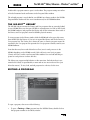
the MX-eDIttM eDItor/LIBrarIan - WInDoWS® anD MactM ..35
Installing the MX-Edit Editor/Librarian Software - Windows ............................. 35
Installing the MX-Edit Editor/Librarian Software - Mac ..................................... 36
Quick Start ............................................................................................................. 36
The MX-Edit Library .............................................................................................. 37
Editing a Program ................................................................................................. 37
The MX-Edit Program Editor ................................................................................ 38
Saving a Program.................................................................................................. 40
Storing a Program ................................................................................................. 41
Archiving ................................................................................................................ 41
uSInG the MX400 aS a harDWare PLuG-In ..........................42
Installing the MX-Edit Hardware Plug-In ............................................................ 42
Connecting the MX400 .......................................................................................... 42
Software Configuration ......................................................................................... 43
Using the MX400 Plug-In Window ....................................................................... 44
Controls .................................................................................................................. 44
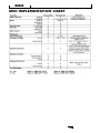
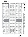
MIDI IMPLeMentatIon chart ..................................................45
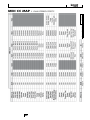
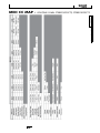
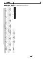
MIDI cc MaPS ..........................................................................46
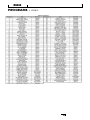
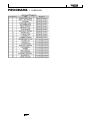
ProGraM LIStS ........................................................................50
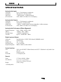
SPecIfIcatIonS ........................................................................53
Introduction
MX400
INTRodUCTIoN
Congratulations and thank you for purchasing the MX400 Dual Stereo/Surround
Reverb Processor! The MX400 provides you with the legendary Lexicon reverbs and
effects powered by four processors, for a wide variety of configurations and blends, all
in a single rack unit. Use the MX400 live or in the studio, connect and control it via
your PC or Mac, or use it as a hardware plug-in. The possibilities are virtually endless!
INCLUded ITeMS
• MX400 Dual Stereo/Surround Reverb Processor
• This owner's manual
• MX Edit/USB driver CD
• Power Cord
• Lexicon Warranty Card
1
Quick Start
QUICK START
Ideally, you should read this entire manual before using the MX400. But, if you just
can’t wait to get started, this section explains how to set up a simple parallel connection (using the MX400 with a mixer) and select a program.
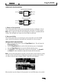
StanDarD ParaLLeL connectIon
1. Connect the mixer’s Post Fader Aux Send outputs to the MX400’s Left and Right
(Front) inputs.
2. Connect the MX400 Left and Right (Front) outputs to a stereo Aux Return input
on the mixer (or a stereo line input, or two adjacent line inputs if you like).
Aux
Return 1
Aux
Return 2
Aux
Send 1
Aux
Send 2
PoWerInG the unIt
1. Plug the included power cord into an A/C outlet.
2. Connect the power cord to the Power Jack connection on the MX400’s back
panel and turn on the MX400's power.
Power
Set auDIo LeveLS
1. Set the gain on the mixer’s input channel appropriate to the source (vocal mic,
guitar, keyboard, etc.).
2. Set the Aux Master level (if provided on your console) to the 12 o’clock position.
3. Set the Input A level on the MX400 to the 12 o’clock position.
4. Provide source signal (by speaking or singing into the mic, playing guitar,
keyboard, etc.) on the selected mixer channel.
5. Turn up the Aux Send levels on the channel corresponding to the Post-fader send
(Aux 1 and Aux 2 in this example) that the MX400 is connected to until the red
input LEDs light only occasionally. If the red Input LEDs stay lit, too much signal
is being sent to the MX400; reduce the Aux Master or Aux Send on the mixer.
6. Turn up the Aux Return 1 and 2 to the 12 o’clock position, or stereo line input
faders to the 0dB position, if you used that connection.
7. To increase or decrease the amount of effect on the signal, adjust the Aux Send
level on the channel that you want affected.
2
Quick Start
MX400
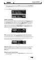
SeLect anD LoaD a ProGraM
Turn the Program/Load knob to choose a program. The Program Number
Display flashes the number of the program to be loaded. Press the knob to load the
program.
Program/Load knob
88
Program Number Display
Note that the MX400 comes with 99 Factory programs and 99 User programs. Factory
and User LED's to the left of the Program Number Display window indicate
whether the displayed program is a Factory or User program. For more information
about editing programs, see page 13.
3
The Front Panel
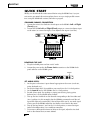
The fRoNT PANeL
1
3
4 5 6 7
9 10 14 15
88
2
8
11 12 13
1. Gain LEDs
Each pair of Gain LEDs indicate input signal strength of each of the MX400’s input
pairs. Range is from -24dB, -12dB, -6dB, and 0dB.
2. Input Knobs A & B
Each Input Knob controls input gain of one stereo input pair.
3. Main Display
The Main Display features six LEDs and an LCD. The LEDs indicate which
Configuration the MX400 is currently using, when the S/PDIF I/O has sync lock, and
USB connectivity. The LCD shows program and parameter editing information and
System Menu settings.
4. Page / Select Knob
Used to navigate the MX400 effects, parameters, and System menus.
5. Exit
Pressing this button will back you out one level of editing.
6. Tempo
Sets the delay time of delay effects.
7. Effect Bypass
Pressing this button bypasses or mutes the selected effects.
8. Edit Knobs A, B, C
These knobs modify the associated parameters in the Main Display when editing programs or change the settings in the System Menu.
9. Store
Used to store or copy programs to the same or different user memory locations.
4
The Front Panel
MX400
10. System
Accesses the System global setup menus.
11. Bypass
Used to bypass or mute the currently selected program.
12. User and Factory LEDs
Indicate whether the selected program is User or Factory.
13. Program Number Display
Displays the number of the selected program.
14. Program / Load
Selects factory and user programs. Pressing this knob loads the program manually if
program Auto Load is disabled.
15. Power Switch
Turns the MX400 on and off.
5
The Rear Panel
The ReAR PANeL
1
2 3
4
5
6
7
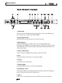
1. Power Jack
Attach the power cord here.
2. USB Port
Provides communication with a computer for use with MX-EditTM Editor/Librarian
software and MX400 plug-in window using a standard USB cable. When the MX400 is
connected to a computer via USB, the blue USB LED next to the main display will light.
3. Footswitch Input
The optional Lexicon® LEX-DFS 2-button footswitch can be plugged into this TRS
jack for remote control of the MX400 (see page 34 for more information).
4. MIDI In, MIDI Thru
Provides MIDI operation capabilities. Two 5-pin MIDI DIN connectors are available for
MIDI IN and MIDI THRU. (See page 50 for MIDI Implementation charts.)
5. S/PDIF Digital In/Out
Digital input accepts 44.1kHz / 48kHz signals. When the S/PDIF digital input is selected and active, the S/PDIF LED on the front panel lights.
Important: It is recommended that you do not connect any digital device to the
MX400’s S/PDIF inputs that transmits at sample rates other than 44.1 kHz or 48 kHz
(such as 96kHz). Doing so can cause unpredictable performance. Make sure the device
you are connecting to the MX400’s S/PDIF In is set as the Clock Master (if that option
is available) and transmitting at a sample rate of 44.1kHz or 48kHz only. As with any
other connection, if you need to unplug the S/PDIF cable, it is recommended that you
switch to the analog inputs (see Input Source in the System menus) or bypass both
processors before disconnecting the cable.
6
The Rear Panel
MX400
6. Balanced Analog Line Output Pairs
Dual RF-filtered 1/4" balanced/unbalanced TRS or balanced XLR line outputs are
servo-balanced, so no signal loss is incurred when using unbalanced connections (1/4"
inputs only). If only a single plug is connected to the Left output, both Left and
Right signals can be summed to mono by selecting Mono Left for analog output A
or B in the System Menu. Pairs are grouped and labeled as A - Front (Stereo) and
B - Rear.
7. Balanced Analog Line Input Pairs
Left and Right active analog 1/4” TRS or XLR balanced line inputs. If only a single
plug is connected to the Left input, the signal can be split and sent to both the Left
and Right input paths by selecting Analog Mono L for input source A or B in the
System Menu. Pairs are grouped and labeled as A - Front (Stereo) and B - Rear.
7
About the MX400
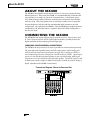
AboUT The MX400
The MX400 is an extremely versatile effects processor; in fact it can operate like three
different processors. When using the MX400, it is recommended that you decide what
type of processor you need it to operate as (Surround, Stereo, or Dual Stereo processor), make the proper cable connections, and select the Configuration that coincides
with your setup. Each Configuration has its own bank of factory and user programs
that are designed to work best with the recommended audio connections for each
Configuration (see Connecting the MX400). Since the MX400 offers multiple processor
configurations, the following section is a guide to help select which Configuration is
best for your needs.
CoNNeCTING The MX400
The MX400 has four inputs and four outputs grouped in pairs A - Front (Stereo) and
B - Rear. There are also two S/PDIF input/output connectors (A and B) that are the
digital equivalent of these analog input and output pairs.
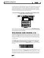
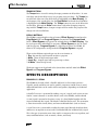
SurrounD confIGuratIon connectIonS
The MX400 is the first processor in its class to provide true surround reverb processing.
The surround reverb algorithm always uses both output pairs A and B (analog and
S/PDIF) and can accept stereo input signals via Input Pair A (analog or S/PDIF) or
true 4-channel input sources via input pair A and B (analog or S/PDIF). Input/output
pair A is for use with the front stereo speakers in your surround system, while input/
output pair B is for use with the rear left and right speakers. The S/PDIF outputs A and
B always mirror analog outputs A and B but input pairs A and B can only be analog or
digital (selectable in the MX400’s System menu)
Connection Diagram: Stereo In/Surround Out
Return 1 2 3 4
8
Send 1
Send 2
Connecting the MX400
MX400
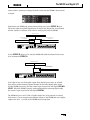
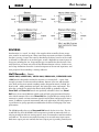
Connection Diagram: Surround In/Out
Return 1 2 3 4
Send 1 2 3 4
Stereo confIGuratIon connectIonS
Stereo Mode configures the MX400 as a single stereo input/output processor utilizing
input/output pair A only (analog and S/PDIF). Input/output pair B is disabled when
the Stereo configuration is selected. S/PDIF output A mirrors analog output pair A but
input pair A can only be analog or digital (selectable in the MX400’s System menu).
Connection Diagram: Dual Mono In/Dual Mono Out, Dual Mono In/Stereo Out, Stereo In/Stereo Out
Return 1
Return 2
Send 1
Send 2
DuaL Stereo confIGuratIon connectIonS
The MX400’s Dual Stereo configuration shows off the MX400’s true power by providing
two independent stereo processors, with each processor running independent programs
from the other. These processors are labeled A and B and utilize their respective analog and digital inputs and outputs (A and B) on the rear panel. The S/PDIF outputs
A and B always mirror analog outputs A and B but input pairs A and B can only be
analog or digital (selectable in the MX400’s System menu).
9
The MX400 and Digital I/O
For sources that will run through Program A (this is the program shown in the top half
of the Program Display which uses Effect 1 and Effect 2), connect to the A Left/Right
(Front) input and output pair. Sources running through Program B (this is the program shown in the bottom half of the Program Display which uses Effect 3 and Effect
4), connect to the B Left/Right (Rear) input and output pair.
Connection Diagram: Dual Mono In/Dual Mono Out, Dual Mono In/Stereo Out, Stereo In/Stereo Out (x2)
Return 1 2 3 4
Send 1 2 3 4
Once you have your connections made, you should refer to the Effect/Mix Routing
section of the manual for understanding how the signal sources can be routed through
each configuration’s programs and effects.
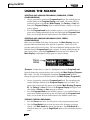
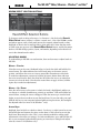
The MX400 ANd dIGITAL I/o
The MX400 is equipped with two digital inputs and outputs (S/PDIF A and B). Each
S/PDIF pair is the digital equivalent of analog input/output pairs A and B. The digital
outputs on the MX400 are always active and will always mirror their analog output
counterparts. This allows you to plug in an analog input source and have it be output
as a digital stream.
The MX400 has three options for input sources which are configurable in the System
Menu: Analog Mono Left, Analog Stereo and Digital. (Press the System
button to access the System Menu; turn the Page/Select knob to scroll up and down
the menu.)
Each input pair (A and B) can have different audio sources selected depending on your
needs. While in the System Menu, use Knobs A, B, and C to change values. As with
all equipment that receives digital audio streams, when setting either Input Source A or
B to Digital, the MX400 can no longer use its own internal clock source for the audio
10
The MX400 and Digital I/O
MX400
stream, and it is necessary to change the clock source from the MX400’s internal clock
to Digital.
Furthermore, the MX400 only receives external clock sync on the S/PDIF A input.
This means when using both Digital inputs (A and B), the devices that are connected
must be synced to a common clock source to work properly with the MX400.
Master Clock Source
External Processor A or
Audio Interface
External Processor B or
Audio Interface
S/PDIF In
S/PDIF Out
S/PDIF In
S/PDIF Out
S/PDIF
MIDI
USB
FOOTSWITCH
IN
THRU
IN
OUT
If only S/PDIF B input is to be used, the MX400 still needs the external clock source
to be connected to S/PDIF A.
Master Clock Source
External Processor or
Audio Interface
S/PDIF In
S/PDIF Out
S/PDIF
MIDI
USB
FOOTSWITCH
IN
THRU
IN
OUT
If the Clock Source isn’t changed to Digital when digital input sources are selected,
there will be synchronization problems between the incoming digital audio stream
and the MX400’s processing, and the System Input Source menu will display DIG NO
LOCK. When the MX400 is properly synchronized with the incoming digital audio,
the System’s Input Source menu will display DIGITAL.
The MX400 only runs at 44.1 kHz or 48 kHz sample rate (using internal or external
clock sources). Do not connect external digital outputs to the MX400 that run at higher
sample rates (88.2 - 192 kHz) as the MX400 cannot accept them.
11
Using the MX400
USING The MX400
SeLectInG anD LoaDInG ProGraMS (SurrounD, Stereo
confIGuratIonS)
1. Choose a program by rotating the Program/Load knob. The selected program
number flashes in the Program Display until loaded. The name of the program also appears in the MX400’s Main Display. The Factory or User LED
next to the Program Display lights to indicate whether a Factory or User program is selected.
2. Press the Program/Load knob to load the program. If you would like the programs to be loaded automatically as they are selected with the Program/Load
knob, you can enable the Auto Load function in the MX400’s System menu.
SeLectInG anD LoaDInG ProGraMS (DuaL Stereo
confIGuratIon)
When using the MX400’s Dual Stereo Configuration, the Main Display shows two
program names simultaneously at the top level of operation. Next to one of the
program names will be a focus arrow. This arrow determines which program will be
changed when the Program/Load knob is rotated. To change which program the
focus arrow points to, rotate the Page/Select knob until one of the effects in the
Main Display is highlighted in the program you want to change.
(Example: If either effect 1 or effect 2 is highlighted, turning the Program/Load
knob will change the program shown in the top half of the Main Display (Program
A). If effect 3 or effect 4 is highlighted, turning the Program/Load knob will
change the program shown in the bottom half of the Main Display (Program B)).
1. Choose a program by rotating the Program/Load knob. The selected program
number will begin flashing in the Program Display until it is loaded. The
name of the program will also appear in the MX400’s Main Display (Program
B). The Factory or User LED next to the Program Display will light to indicate whether a Factory or User program is selected.
2. Press the Program/Load knob to load the program. If you would like the programs to be loaded automatically as they are selected with the Program/Load
knob, you can enable the Auto Load function in the MX400’s System menu.
StorInG/coPyInG ProGraMS
1. Press the Store button once. You will now be on the program naming screen.
2. Turn the Page/Select knob to move the cursor to the character you want to
change. Turn Edit Knob A to change the character. Turn Edit Knob B to
change the letter case. Press the Page/Select knob to clear a character from the
name.
12
Using the MX400
MX400
3. When naming is complete, press the Store button again. Turn the Page/Select
or Program/Load knob to select the new user program memory location to store
to.
4. Press the Store button again to complete the store procedure.
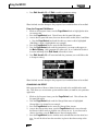
eDItInG a ProGraM
Once a program has been loaded, you may find you want to make adjustments to it for
your particular application. Editing of programs is done using the Page/Select and
three Edit Knobs (A, B, and C) to the right of the Main Display. Each effect can
be edited independently by selecting it with the Page/Select knob. As the effect is
selected, its name is highlighted in the Main Display and three parameters become
visible for the effect at the bottom of the Main Display. The Edit Knobs can then
modify these three top level parameters.
(Fig. A)
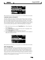
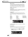
Note: Dual Stereo programs feature a slightly different program screen which displays both program names. When Edit Knobs A, B, and C are turned, the three
parameters of the selected effect will be displayed momentarily for editing purposes and
then the name of the second program will reappear. (Fig. B shows Tape Delay as the
selected effect in a Dual Stereo Configuration program).
(Fig. B)
Edit Knobs A, B, and C will modify the Tape Delay effect’s Tempo, Delay Time, and
Feedback parameters respectively. In addition, Surround and Stereo Configuration
program effects have several other parameters that can be modified from the Edit
Effect menus.
Editing From the Program Display
1. While on the program screen, turn the Page/Select knob to highlight the effect
you want to edit.
13
Using the MX400
2. Turn Edit Knob A, B, or C Edit to modify a parameter setting.
When finished, store the changes to the program if you would like them to be recalled.
From the Program Edit Menus
1. While on the Program Screen, turn the Page/Select knob to highlight the effect
you want to edit.
2. Press the Page/Select knob. This will enter the Program Edit menus.
3. Once in the Program Edit menu, there can be two effects to edit, Effect 1 and Effect
2. Turn the Page/Select knob until the effect you want to edit is highlighted
(Edit Effect 1 menu is highlighted in our example).
4. Press the Page/Select knob to enter the Edit Effect menu.
5. Turn the Page/Select knob until the parameter(s) you want to edit appear in
the Main Display. Each parameter has either an A, B, or C labeled to the left of
its name indicating which Edit Knob will modify its value.
6. Turn Edit Knob A, B, or C associated with the parameter you would like to edit
to change its setting.
When finished, store the changes to the program if you would like them to be recalled.
chanGInG an effect
Each program offers a library of effects that can be used in the available effect modules. This allows you to customize a preset with the effects you need for your particular
application.
1. While on the Program Screen, press the Page/Select knob. This will enter the
Program Edit menus.
2. Turn the Page/Select knob until the Change Effect menu is highlighted.
Change Effect 2 is selected in our example.
3. Press the Page/Select knob to enter the Change Effect 2 menu.
4. Once in the change effect menu, turn the Page/Select knob to move through
the library of effects until you find the one you want to use. If you choose not to
select a new effect, press the Exit button to abort changing effects.
5. Press the Page/Select knob to load the newly selected effect into the effect location. You will be able to hear the new effect in place in the effect routing at this
time.
14
MX400
Using the MX400
When finished, store the changes to the program if you would like them to be recalled.
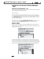
chanGInG knoB aSSIGnMentS
The three parameters that appear for editing from the Program Screen in Surround
and Stereo Configuration programs are user selectable. From the factory, these parameters were selected in each program by their importance to the effect. If you would
like to access other parameters for each effect from the Program screen, you can select
these in the Knobs Assign menu. These assignments are individual to each program so
you can customize specific parameters for each effect depending on the program.
1. While on the Program Screen, press the Page/Select knob. This will enter the
Program Edit menus.
2. Turn the Page/Select knob until the Knobs Assign menu is highlighted. Edit/
Mix Routing is selected in our example.
3. Press the Page/Select knob to enter the Knobs Assign menu.
4. Turn either the A, B, or C knobs to select which parameter you want available for
editing from the Program Screen.
When finished, store the changes to the program if you would like them to be recalled.
effect MIX/routInG
Each of the MX400 programs offers programmable effect routing and a wet/dry mix
parameter for each effect. These different routings and mix controls give you many
options for your effect signal path and precise control over balance between the two
effects. In Dual Stereo Configuration programs, Effects 1 and 2 are used by Program A
(the program shown in the top half of the Program Display), while Effects 3 and 4 are
used by Program B (the program shown in the bottom half of the Program Display).
Routings for all configurations are as follows:
15
Using the MX400
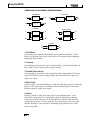
Stereo anD DuaL Stereo confIGuratIonS
1. Dual Mono
2. Cascade
L
Effect 1/3
L
R
Effect 2/4
R
L
R
Effect 1/3
3. Parallel
L
R
L
R
Effect 2/4
4. Mono Split
L
Effect 1/3
Effect 2/4
R
L
Effect 1/3
R
Effect 2/4
L
R
5. Stereo
L
R
Effect 1/3
L
R
1. Dual Mono
This routing option sends the Left and Right input signals through Effect 1/3 and
Effect 2/4 respectively. Each signal is then routed to its respective output, completely
independent from the other.
2. Cascade
Left and Right input signals are sent first through Effect 1/3, then through Effect 2/4,
then routed as a stereo signal to their respective outputs.
3. Parallel (Dual Stereo)
Left and Right input signals are sent through both effects independently. The output
signals of both Effects are then mixed together, and routed to both the outputs as a
single stereo signal.
4. Mono Split
Left input signal is sent through Effect 1/3, while the Right input signal is sent through
Effect 2/4. The output signals of both Effects are then mixed together, and routed to
both the outputs as a single stereo signal.
5. Stereo
Routing 5 provides a single stereo effect path for Left and Right signals. In the
Dual Stereo configuration, this routing utilizes all the DSP horsepower allocated
to the program, thus letting you use the expanded effects library used by the Stereo
Configuration programs. In Stereo programs, this routing removes one of the effect
modules allowing for users requiring a streamlined signal path with only a single
effect for their needs.
16
Using the MX400
MX400
SurrounD confIGuratIon
1. Stereo In/Surround Out
(Front)
L
R
Surround
Reverb
L (Front)
R
L (Rear)
R
2. Surround In/Out
L
(Front)
R
L
(Rear)
R
Surround
Reverb
L (Front)
R
L (Rear)
R
1. Stereo In/ Surround Out
This routing option takes a stereo source connected to the Left 1 and Right 1 (Front)
inputs, processes them through the Surround reverb, and sends it to all four outputs.
Note: Only a single mix control for the Left/Right front outputs is available with this
routing. The Left/Right rear outputs are always 100% wet processed.
2. Surround In/Out
This routing option takes a surround input source connected to all of the MX400
inputs, processes through the Surround reverb, and sends it to all four outputs.
eDItInG effect MIX/routInG
1. While on the Program Screen, press the Page/Select knob. This will enter the
Program Edit menus.
2. Turn the Page/Select knob until the Edit Mix/Routing menu is highlighted.
3. Press the Page/Select knob to enter the Edit Mix/Routing menu.
4. Turn Knob A to select different effect routings for the program. Use Knob B
and Knob C (when available) to adjust the wet/dry mix for each effect.
Note: In Surround Configuration programs using the Stereo In/Surround Out routing
(1) and in Stereo and Dual Stereo Configuration programs using the stereo routing
(5), there is only one effect available so Effect 2 Mix will not be available.
When finished, store the changes to the program if you would like them to be recalled.
17
Effects Descriptions
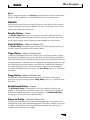
teMPo Button
The Tempo button is used for setting the tempo parameter in delay effects. In some
cases there may be two delays set up in a program using two effects. The Tempo button will flash at the rate of the delay which is highlighted in the Main Display. To
set the tempo of the second delay, turn the Page/Select knob until the second delay
is highlighted in the Main Display. The Tempo button can now set the delay time
for this delay. Although the Store button doesn't light when changing tempo settings with the Tempo button, changes to tempo must be saved to the program if the
changes are to be recalled later.
ByPaSS ButtonS
The MX400 is equipped with two bypass buttons: Effect Bypass (located near the
Page/Select knob and Program Bypass (located near the Program/Load
knob). Effect Bypass only bypasses the selected effect in the Main Display. This
lets you bypass effects individually in programs. Effect Bypass can also be saved
with the program. Program Bypass is a global bypass control for MX400. All
effects in all configurations are bypassed when Program Bypass is engaged.
There are four different options Bypass can be set to function as:
1. Dry - Bypasses dry signal around an effect or program.
2. Mute - Mutes all input and output audio.
3. Input Dry - Outputs signal with no processing or effects.
4. In Mute - Mutes the input only.
The Bypass options can be selected in the System Menu and will affect both Effect
Bypass and Program Bypass.
effeCTS deSCRIPTIoNS
ParaLLeL vS. SerIaL
The MX400 can be used as both a Parallel and Serial (in-line) effects processor.
Typically, reverbs and delays are used in parallel, compressors and de-essers in serial,
and modulated effects can be used in either configuration, depending on the desired
application.
A Parallel Processor is connected by sending a copy of a signal (such as from an Aux
Send of a mixer channel) to an effects device (such as the MX400), and the effected
(or wet) signal is returned to the mixer or amp. It is then blended together with the
original unaffected (dry) signal. This blend is called the Wet/Dry mix. This connection
is most often used for reverbs, delays, and some modulated effects (such as chorus).
A Serial Processor is connected by sending the entire signal through the effects device
and then to an amplifier or mixer, and is not blended with the unaffected (dry) signal.
This is the type of connection most often used for a compressor, de-esser, equalizer, and
many modulated effects (such as tremolo, vibrato, and rotary).
18
MX400
Effects Descriptions
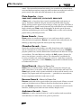
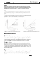
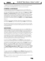
ReveRbS
Reverberation (or “reverb” for short) is the complex effect created by the way we perceive sound in an enclosed space. When sound waves encounter an object or boundary,
they don’t just stop. Some of the sound is absorbed by the object, but most of the sound
is reflected or is diffused. In an enclosed space, reverb is dependent on many features of
that space, including the size, shape and the type of materials that line the walls. Even
with closed eyes, a listener can easily tell the difference between a closet, a locker room
and a large auditorium. Reverb is a natural component of the acoustic experience, and
most people feel that something is missing without it.
Hall Reverbs - Stereo
SMaLL haLL, LarGe haLL, vocaL haLL, DruM haLL, SurrounD haLL
A Hall reverb is designed to emulate the acoustics of a concert hall – a space large
enough to contain an orchestra and an audience. Because of the size and characteristics, Halls are the most natural-sounding reverbs, designed to remain “behind” the
direct sound – adding ambience and space, but leaving the source unchanged. This
effect has a relatively low initial echo density which builds up gradually over time.
Vocal Hall and Drum Hall reverbs are specifically tailored for those uses. Vocal
Hall has as lower overall diffusion which works well with program material that has
softer initial transients like a voice. Drum Hall has a higher diffusion setting which is
necessary to smooth out faster transient signals found in drums and percussion instruments. In addition to general instrumental and vocal applications, the Hall program is
a good choice for giving separately recorded tracks the sense of belonging to the same
performance.
The MX400 proudly offers a true Surround Hall reverb, the first in its class. The Surround Hall uses all of the MX400’s DSP horsepower to provide an immensely lush, enveloping reverb that offers two routing options: stereo in/surround out and surround in/
surround out. The stereo in/surround out routing is for use with stereo input sources.
Both stereo output pairs are used with the front (output pair A) providing a wet/dry mix
19
Effects Descriptions
control. The surround in/surround out routing is for use with a true 4-channel input
source and both front and rear output pairs each have their own wet/dry mix control for
precise control of dry audio and reverb adjustments in the surround field.
Plate Reverbs - Stereo
SMaLL PLate, LarGe PLate, vocaL PLate, DruM PLate
A Plate reverb is a large, thin sheet of metal suspended upright under tension on
springs. Transducers attached to the plate transmit a signal that makes the plate
vibrate, causing sounds to appear to be occurring in a large, open space. The Plates in
the MX400 model the sound of metal plates with high initial diffusion and a relatively
bright, colored sound. Plate reverbs are designed to be heard as part of the music,
mellowing and thickening the initial sound. Plate reverbs are often used to enhance
popular music, particularly percussion.
Room Reverb - Stereo
Room produces an excellent simulation of a very small room which is useful for
dialog and voiceover applications. Room is also practical when used judiciously for
fattening up high energy signals like electric guitar amp recordings.
Chamber Reverb - Stereo
Historically, recording studio chambers were oddly shaped rooms with a loudspeaker
and set of microphones to collect ambience in various parts of the room. Chamber
programs produce even, relatively dimensionless reverberation with little color change
as sound decays. The initial diffusion is similar to the Hall programs. However, the
sense of size and space is much less obvious. This characteristic, coupled with the
low color of the decay tail, makes these programs useful on a wide range of material
- especially the spoken voice, to which Chamber programs add a noticeable increase
in loudness with low color.
Gated Reverb - Mono In/Stereo Out
Gated reverb is created by feeding a reverb, such as a metal plate, through a gate
device. Decay Time is set to instant, while Hold Time varies duration and sound. The
Gated reverb provides a fairly constant sound with no decay until the reverb is cut off
abruptly. This program works well on percussion — particularly on snare and toms;
be sure to experiment with other sound sources as well.
Reverse Reverb - Mono In/Stereo Out
Reverse reverb works in the opposite fashion from normal reverb. Whereas a normal
reverb has the loudest series of reflections heard first that then become quieter over
time, the Reverse reverb has the softest reflections (essentially the tail of the reverb)
heard first, and then grows louder over time until they abruptly cut off.
Ambience Reverb - Stereo
Ambience is used to simulate the effect of a small or medium sized room without
noticeable decay. It is often used for voice, guitar or percussion.
20
MX400
Effects Descriptions
Studio Reverb - Stereo
Much like Room reverb, Studio produces an excellent simulation of smaller,
well-controlled acoustic spaces, characteristic of the main performance areas in
recording studios. Studio is also useful with dialog and voiceover applications
as well as individual instrument and electric guitar tracks.
Arena Reverb - Stereo
Arena reverb emulates a huge physical space such as an indoor sports venue
or stadium. The characteristics of Arena reverb are long secondary reflection
times and a reduced amount of high frequency content. Arena is a mostly
mid- and low-frequency dominant reverb, and is an ideal selection for “special
effect” type applications that require extremely long reverb times. It is not a
good choice for a very busy mix, since it can reduce intelligibility.
Spring Reverb - Mono In/Stereo Out
A Spring reverb is created by a pair of piezoelectric crystals—one acting as a
speaker and the other acting as a microphone—connected by a simple set of
springs. The characteristic ‘boing’ of a spring is an important component of
many classic rock and rockabilly guitar sounds.
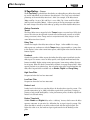
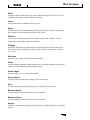
Reverb Controls
Pre Delay
Creates an additional time delay between the source signal and the onset of
reverberation. This control is not intended to precisely mimic the time delays
in natural spaces, as the build-up of reverberation is gradual, and the initial
time gap is usually relatively short. For the most natural effect, the Pre Delay
values should be set in the range of 10-25 milliseconds. However, if a mix is very
busy or overly cluttered, increasing the Pre Delay time may help clarify it, and
set each instrument apart from each other.
Mid RT and Decay
Controls the amount of time the reverb can be heard. Higher settings increase
reverberation times which are usually associated with larger acoustical environments, but can decrease intelligibility. Lower settings shorten reverb times and
should be used when a smaller apparent space or a more subtle effect is desired.
Diffusion
Controls the initial echo density. High settings of Diffusion result in high initial
echo density, and low settings cause low initial density. In a real-world situation,
irregular walls cause high diffusion, while large flat walls cause low diffusion.
For drums and percussion, try using higher Diffusion settings.
Shape & Spread
In the Hall reverbs, Shape and Spread work together to control the overall
ambience of the reverberation. Shape determines the contour of the
reverberation envelope. With Shape all the way down, reverberation builds
explosively, and decays quickly. As Shape is advanced, reverberation builds
21
Effects Descriptions
up more slowly and sustains for the time set by Spread. With Shape in the middle,
the build-up and sustain of the reverberation envelope emulates a large concert hall
(assuming that Spread is at least halfway up, and that Size is 30 meters or larger). Low
Spread settings result in a rapid onset of reverberation at the beginning of the envelope,
with little or no sustain. Higher settings spread out both the buildup and sustain.
Size
Size sets the build-up rate of diffusion after the initial period (which is controlled
by Diffusion). The Size control changes reverb sound from very large to very small.
Generally, set this control to the approximate size of the acoustic space being created,
before adjusting anything else. The size in meters is roughly equal to the longest
dimension of the space. Audio is temporarily muted when Size is changed.
RT High Cut
Rt HC sets the frequency above which a 6dB/octave low-pass filter attenuates the reverberated signal. It does not attenuate the reflections. High frequencies are often rolled
off with this parameter, resulting in more natural-sounding reverberation. Setting a
low frequency for this parameter can actually shorten the reverb time, as it damps the
audio as it recirculates.
Liveliness
Adjusts the amount of high frequency content in the reverberation tails. Higher settings
increase high frequency response, creating brighter reverbs; lower settings create darker
reverbs with more bass frequency emphasis.
Bass Boost
Bass Boost boosts or cuts frequencies below Crossover. The amount of boost or cut
required is highly dependent on the material being processed.
Bass Boost Frequency
Sets the frequency at which the transition from Mid Rt to Low Rt takes place. This control should be set at least two octaves higher than the low frequency you want to boost.
For example, to boost a signal at 100Hz, set Bass Boost Frequency to 400Hz. (This
setting works well for classical music.) Crossover works best around 400Hz for boosting
low frequencies, and around 1.5 kHz for cutting low frequencies.
ER Time
Adjusts the amount of time before reverb early reflections occur.
ER Level
Adjusts the level of early reflections within the reverb.
Feedback Delay
Changing this parameter changes the resonant frequencies of Plate reverb.
Feedback Level
Adjusts the Plate reverb's presence and prominence.
22
Effects Descriptions
MX400
Boing
This is a unique parameter to the Spring reverb, designed to increase or decrease the
amount of spring rattle that is a physical characteristic of spring tank reverbs.
deLAyS
Delays repeat a sound a short time after it first occurs. Delay becomes echo when the
output is fed back into the input (feedback). This turns a single repeat into a series of
repeats, each a little softer than the last.
Studio Delay - Stereo
The Studio Delay features up to 2.5 seconds of stereo delay and offers a built-in
ducker that attenuates the delay output whenever signal is present at the input. This
can be used to keep the original signal from being muddied up by delay repeats.
Digital Delay - Mono In/Stereo Out
The Digital Delay is the cleanest, most accurate of the delay programs, with up to 5
seconds of mono delay and the built-in ducking feature.
Tape Delay - Mono In/Stereo Out
In the days before digital, delays were created using a special tape recorder in which
the magnetic recording tape was looped, with closely-spaced recording and playback
heads. The delay effect was created by the tape moving in the space between the record
and playback heads – while delay time was adjusted by changing the speed of the tape
loop. Although very musical-sounding, wow and flutter combined with a significant
loss of high frequencies, and to some extent also low frequencies, are all elements
commonly associated with tape recordings. The Tape Delay offers up to 5 seconds of
mono delay.
Pong Delay - Mono In/Stereo Out
This delay effect pans the delay repeats from left to right, while the input signal
remains at its original (center) position. Pong Delay offers up to 5 seconds of mono
delay time.
Modulated Delay - Stereo
The Modulated Delay is enhanced by an LFO (low frequency oscillator) that
produces a chorusing effect on the delay repeats. This is a great delay for guitar and
instrument passages that need that “special something.” The Modulated Delay
features up to 2.5 seconds of stereo modulated delay.
Reverse Delay - Mono In/Stereo Out
This delay effect emulates the old studio trick of flipping a tape over, playing it backwards through a tape delay, and recording the effect. The delays “build up” from softer
to louder – creating the sensation that the delays come before the signal. Up to 2.5
seconds of mono delay time are available.
23
Effects Descriptions
2-Tap Delay - Stereo
The 2-Tap Delay is probably best described as an adjustable pong delay where each
tap can be individually set in relation to the delay time. The 2 taps are a calculated
percentage of the actual delay time from 1-100% (for example, if the delay time is
500ms and Tap 1 is set to 50% and Tap 2 is set to 100%, Tap 1 time would be 250ms
and Tap 2 time would be 500ms). Narrow spacing of the tap percentages can widen
the stereo image of the delay while wider tap spacing can create rhythmic delay lines.
Delay Controls
Tempo
The actual delay time as tapped in by the Tempo button or received via a MIDI clock
source. This time can be expressed as actual time (milliseconds, seconds) or in BPM
(beats per minute) values. Tempo works in conjunction with Delay Range to set the
actual delay time that is heard.
Delay Time
Controls the length of the delay time relative to Tempo. At the middle of its range,
delay repeats are synchronous with the Tempo button (represented by a Quarter Note
in the display); lower values create faster repeats, while higher values increase the time
between repeats.
Feedback
Controls the number of delay repeats by feeding the delay output signal back into the
delay input. This creates a series of delay repeats, each slightly attenuated until they
become inaudible. Higher settings create more repeats; lower settings reduce the number of repeats. When this knob is turned fully clockwise, it engages Repeat Hold – delay
repeats play back in an infinite loop, but no further input signal is introduced into the
delay effect. Repeat Hold is available only on Studio, Digital and Pong Delay.
High Pass Filter
Frequencies below this level are attenuated.
Low Pass Filter
Frequencies above this level are attenuated.
Ducker Level
Ducker Level is the level you want the delay to be heard at when signal is present. This
provides attenuation (up to 18dB) of the delay signal while a performer is singing or
playing to help provide intelligibility. As the performance pauses, the delay signal level
returns to its normal setting.
Ducker Threshold
MX400’s Studio and Digital delays offer a “ducking” feature, which causes the delay
repeats to attenuate (or get softer) by –6dB when live (or input) signal is present. This
allows the delay to remain as an effect, and not clash with the original signal. The
higher this value is set, the louder an input signal must be for the ducking to take
place.
24
Effects Descriptions
MX400
Smear
This parameter controls the amount of “smear,” or signal degradation and frequency
loss. Particularly evident in the Tape Delay, the higher the setting, the more each
delay repeat loses intelligibility compared to the original signal.
Tap 1 & 2
The Tap parameters provide independent control to the two delay taps in the 2-Tap
Delay. Each tap can be set to a percentage of the delay tempo, creating interesting
rhythmic delay lines not available in the other delays.
Level 1 & 2
Adjusts the output level of Tap 1 and Tap 2.
Pan 1 & 2
Adjusts the pan position in the stereo field of Tap 1 and Tap 2.
Mod Depth
This controls the intensity of modulation, or “depth” in the Modulated Delay.
Lower settings produce a more subtle chorus effect, while higher values give a more
lush chorusing of the delay repeats.
dbx® dyNAMICS
The MX400 offers two dynamics processing modules, De Esser and Compressor, that
utilize dbx’s legendary digital dynamics processing technology to produce professionalquality reverbs and effects.
De-Esser - Stereo
A De-Esser is a type of compressor used to tame excessive sibilance, or the “s”
sounds in a vocal performance. Note that the De-esser does not pass dry audio.
Compressor - Stereo
A compressor is used to control the dynamic range of a signal. Typically used to tighten
bass or drum tracks, or to control a vocal passage, a compressor is a very useful but
often misunderstood tool. To better use the Compressor in the MX400, a bit of
understanding about compression is helpful. Note that the Compressor does not pass
dry audio.
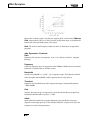
When a signal level crosses the Threshold level, the compressor then reduces the
amount of output level by an amount determined by the Ratio. For example, if the
threshold is set to –12dB, and the ratio set to 4:1, then when signal exceeds –12dB, the
signal level above that amount only increases by 1dB to every 4dB of signal level above
–12dB. In this case, an incoming signal of –4dB (which is 8dB above the threshold)
would result in an output signal of –10dB, or 2dB higher than the threshold level,
since the 4:1 compression ratio only allowed 2dB more output, based on the 8dB
increase above the –12dB threshold.
25
Effects Descriptions
Because the resulting output is less than the original signal, a third control, Makeup
Gain compensates for this loss of level, but with less dynamic range, or the difference
between the softest and loudest parts of the signal.
Note: The De-Esser and Compressor effects are Mono In Dual Stereo configuration
programs.
dbx Dynamics Controls
Ratio
Determines the amount of compression, from 1:1 (no effect) to Infinity:1 (complete
limiting).
Frequency
Selects the frequency range of compression from 1600Hz to 10kHz (the most common
frequencies in which excessive sibilance occurs).
Bandwidth
Controls the bandwidth or “Quality” (Q) of frequency range. The higher the selected
value, the tighter the bandwidth, and less apparent the de-essing effect is.
Threshold
Determines the threshold above which compression begins, incrementally between
–70dB and 0dB.
Gain
Increases the output level to compensate for signal attenuation during compression.
Incremental between 0dB (no gain) to +12dB.
Attack
Attack adjusts the attack time constant, determining how quickly the compressor
responds to increasing input level. This should normally be set quite low to allow the
compressor to react to sharp transients.
26
MX400
Effects Descriptions
Release
Release allows adjustment of the release time constant, determining how quickly the
compressor responds to decreasing input level. This should normally be set long. Short
release times may cause an effect similar to “pumping” in an analog compressor.
Knee
In Hard Knee mode, the threshold of compression is defined as that point above which
the output level no longer changes on a 1:1 basis with changes in the input level. See
Figure 1.
In Soft Knee mode, the threshold of compression is defined as the middle of the threshold
region, that is, “half-way” into compression, as shown in Figure 2.
ModULATed effeCTS
Chorus - Stereo
Chorus creates a lush, full sound by combining two or more signals together where
one is unaffected and the other signals vary in pitch very slightly over time. Chorus
is commonly used to fatten up tracks and to add body to guitars without coloring the
original tone. Chorus can also be used with discretion to thicken a vocal track.
Flanger - Stereo
This effect was originally created by simultaneously recording and playing back two
identical programs on two tape recorders, then using hand pressure against the flange
of the tape reels to slow down first one machine, then the other. The result was a series
of changing phase cancellations and reinforcements, with characteristic swishing, tunneling, and fading sounds.
Phaser - Stereo
The Phaser automatically moves frequency notches up and down the spectrum of the
signal by means of a low frequency oscillator (LFO), creating an oscillating “combfilter” type effect. This effect is very useful on keyboards (especially pad presets) and
guitars.
27
Effects Descriptions
Tremolo/Pan - Stereo (Wet Only)
Tremolo and Panner create rhythmic changes in signal amplitude. Tremolo
affects both channel’s amplitude simultaneously, while the Panner affects the amplitude of each channel in an alternating manner.
Rotary - Mono In/Stereo Out (Wet Only)
Rotary speaker cabinets were designed to provide a majestic vibrato/choir effect for
electronic theater and church organs. The most well known rotary speaker is the
Leslie™ Model 122, which has two counter-rotating elements: a high-frequency horn
and a low-frequency rotor with slow and fast speeds. The sound generated as the spinning elements change speed is truly magical. The swirling, spacious effect is difficult to
describe – but clearly recognizable.
The Rotary effect is modeled after a Leslie-style cabinet. The input signal is split into
high and low-frequency bands. The rotation effect is created by a synchronized combination of pitch shifting, tremolo, and panning. Like the physical cabinet, the high
(horn) and low (rotor) frequencies are “spun” in opposite directions. Horn and rotor
speeds are independent, and designed with acceleration and deceleration characteristics
to simulate the inertia of the original mechanical elements.
A virtual requirement for organ music, Rotary also sounds remarkable with guitar
and electric piano rhythm parts. In fact, these programs are great alternatives to the
Chorus and Tremolo effects for any sound source.
Vibrato - Stereo (Wet Only)
Vibrato is obtained by smoothly varying the pitch of the signal just sharp and flat of
the original at a determined rate.
Pitch Shift - Stereo
This effect shifts the frequency spectrum of the input signal. Altering the pitch of a
sound produces a wide range effects - from subtle detunes to full interval shifts up
or down a two octave range. The MX400’s Pitch Shift effect is a chromatic shifter,
meaning all notes of the scale are shifted by the same interval. Pitch Shift is very
useful with guitar tracks, monophonic synth lines, or where special vocal effects are
needed.
Detune - Stereo
Detune adds a slightly pitch-shifted version of the original source, thickening the
sound. This creates a particularly effective simulation of “double-tracking.” This effect
is also a great alternative to the Chorus effect, adding the richness of a chorus without the audible sweep caused by the chorus rate.
Modulated Effect Controls
Speed
Sets the speed at which the modulated effect cycles.
28
MX400
Effects Descriptions
Depth
Scales the intensity of the effect. This control affects the output of the LFO only. It has
no effect on the outputs of the individual waveforms.
Voices
Controls the number of additional Chorus voices.
Regen
Controls the amount of modulated signal being fed back into the input, creating feedback. Higher amounts add more resonance to the signal.
Diffusion
Creates a time-smoothing effect similar to diffusion in reverb. Diffusion can be a
subtle effect to add a little warmth to the chorus.
PreDelay
Determines the amount of offset between the two signals that create the flange effect.
Lower values create a tighter effect, higher values result in a more extreme "whooshing" sound.
Waveform
Selects the wave pattern used by the modulated effect.
Phase
Controls whether amplitude or depth change occurs in both left and right outputs simultaneously or alternates between left and right outputs.
Phase Stages
Selects between a 4, 8, or 12 state phase shifter.
Stereo Spread
Increases or decreases the stereo imaging of the Rotary effect.
Drive
Provides overdrive gain to the preamp section of the rotary speaker effect.
Minimum Speed
Sets the minimum speed at which the effect will oscillate.
Maximum Speed
Sets the maximum speed at which the effect will oscillate.
Doppler
Increases or decreases the Doppler pitch effect that is created by the physics of a rotating
speaker.
29
MX400 System Menus
Shift 1 & 2
Determines the amount of pitch shift or detune shift from the original signal source.
Works best with individual notes.
Delay 1 & 2
Sets the delay time before the pitch shift or detune effect is heard in the Pitch Shift and
Detune effects.
Feedback 1 & 2
Adjusts how much of the shifted signal is sent back through the delay line in Pitch
Shift and Detune for creating cascading arpeggio type effects.
Pan 1 & 2
Sets the pan position in the stereo field for each tap in the 2-Tap Delay.
MX400 SySTeM MeNUS
SySteM MenuS
The MX400 System menus are where global settings are configured. These include
Surround, Stereo, or Dual Stereo Configuration, Program Auto Load, Output Level,
and Factory Restore. Changes made to these settings affect all programs in all
Configurations. Press the System button to access these menus. Turn the Page/
Select knob to scroll up and down through the available menus. Press the Exit button
to exit the System Menus.
Configuration
This menu is where you select what kind of processor you want the MX400
to run as (Surround, Stereo, or as a Dual Stereo processor). Use Knob A
to change the MX400's configuration. See page 8 ("About the MX400") for
more information on configurations.
Contrast
This utility adjusts the contrast of the Main Display to make it more visible at different viewing angles. Use Knob B to adjust the display’s viewing angle to your liking.
Program Load
MX400 programs can be loaded manually or automatically as each program is selected. The default setting is Manual. Use Knob C to select
which method of program loading you need.
30
MX400
MX400 System Menus
Input Source A
The MX400 has both analog and digital inputs that can be connected to.
Depending on which inputs you will be using, you need to select between
analog or digital sources. The MX400 offers three different input sources
to select from: Analog Mono L, Analog Stereo, and Digital. Input Source A
refers to whether you will be using analog A - Front (Stereo) inputs or digital input A. When only a single analog input is to be used, select Analog
Mono L and connect to the A - Front (Stereo) Left input only. All inputs
(analog and digital) can remain connected simultaneously in the event
you find yourself switching between using both. Use Knob A to select the
appropriate Input Source you will be using.
Input Source B
Input Source B is identical to Input Source A (explained above) except it
refers to analog and digital Input Pair B only. Use Knob B to select the
appropriate Input Source you will be using.
Clock Source
This option allows manual selection of either the internal or external clock
source for the MX400. When set to 44.1kHz, the MX400 utilizes an internal clock with a 44.1kHz sample rate. When set to 48kHz, the MX400 utilizes an internal clock with a 48kHz sample rate. When set to Digital, the
unit utilizes the S/PDIF input clock source, even if an analog audio source
is used. The MX400 only accepts external digital clock information on the
Digital S/PDIF A input. Refer to The MX400 and Digital I/O section on
page 10 for more information on using digital audio sources. Use Knob C
to select the appropriate Clock Source you will be using.
Analog Output A
The MX400 analog outputs can be configured to run in stereo or in mono.
Each pair of outputs can be configured independently of the other. Analog
Out A refers to only A - Front (Stereo). When only a single output cable is
to be used, connect to the A - Front (Stereo) Left output only and set the
Output mode to Mono Left. Output Mode only affects the analog outputs.
Use Knob A to select between Mono Left and Stereo.
31
MX400 System Menus
Analog Output B
Analog Out B is identical to Analog Out A description but refers to analog
Output Pair B only. Use Knob B to select between Mono Left and
Stereo B - Rear outputs.
Output Level
The MX400 outputs can be optimized to run with equipment requiring
different output levels. High end audio systems run at +4dBu levels while
many inexpensive system levels run at -10dBV levels. Consult the technical
guides that came with the equipment you will be connecting the MX400
to so as determine which output level should be selected. Use Knob C to
change between –10dBV or +4dBu.
Digital Out A/B
The MX400 can send unprocessed digital audio out either of its S/PDIF
Digital Outputs while monitoring processed audio through the analog
outputs. This is useful when you want to record a dry performance digitally,
but also hear effects processing while you are recording. To send unprocessed audio out the MX400 digital outputs, set the Digital Out A and
Digital Out B options to Dry. Turn Knob A to change Digital Out A,
and Knob B to change Digital Out B.
Note: This feature is only available for signals brought into the MX400 via
the analog inputs. It has no effect on signals being received at the S/PDIF
In. Digital in/out signals are processed normally regardless of whether the
Digital Out A/B settings are set to Dry.
Bypass Select
There are four different bypass options for effects and programs (turn
Knob C to select):
Dry – the inputs and outputs of the effects are muted but dry signal
is passed around them.
Mute – The inputs, outputs and dry signal paths are all muted leaving no signal at the outputs.
Input Dry – The inputs to the effects are muted but reverb decay
and delay tails will still finish. Dry signal will also be passed around
the effects.
Input Mute – The inputs and dry paths around the effects are
muted but reverb decay and delay tails will still finish.
32
MX400
MX400 System Menus
MIDI Channel A
The MX400 is equipped with two MIDI receive channels, Channel A
and Channel B. MIDI channel A is the channel used by all MX400
Configurations: Surround, Stereo, and Dual Stereo. Any program change or
CC messages sent to the MX400 on MIDI Channel A will be processed by the
active program. Channels can be set from 1-16, All channels, or Off. Use
Knob A to change MIDI Channel A settings.
Note: In Dual Stereo, there are always two programs active. The program
shown at the top half of the Main Display on the program screen is the
program that will respond to MIDI Channel A messages.
MIDI Channel B
The MX400’s MIDI Channel B channel is a separate channel utilized when
the Dual Stereo Configuration is selected. MIDI messages received
on this channel control the program shown in the bottom half of the Main
Display of the program screen. Channels can be set from 1-16, All
channels, or Off. Use Knob B to change MIDI Channel B settings.
MIDI Clock Sync
The MX400’s MIDI input is able to receive and synchronize delay times via
MIDI clock messages. When set to On, Tap Tempo is changed by incoming
MIDI messages. (The Tempo button on the front panel will be disabled
while these messages are being received.) When set to Off, the unit ignores
MIDI Clock messages. Use the Knob C to change MIDI Receive
options.
MIDI Program Receive
The MIDI Program receive option lets you enable or disable the MX400
from receiving MIDI program change messages. When MIDI Program
Receive is set to off, it filters all program change messages so that the
MX400 will not respondt to them in any configuration (Surround, Stereo,
or Dual Stereo). MIDI CC messages are still received even when this option
is disabled. Use Knob A to change this option.
33
MX400 System Menus
MIDI CC Receive
The MIDI CC receive option lets you enable or disable the MX400 from
receiving MIDI CC messages. When MIDI Program Receive is set to off,
it filters all MIDI CC messages so that the MX400 will not respond them
in any configuration (Surround, Stereo, or Dual Stereo). MIDI program
change messages are still received even when this option is disabled. Use
Knob B to change this option.
Tempo Display
MX400 programs can display delay time in two types of units, ms (milliseconds) and BPM (beats per minute). Use Knob C to select which units you
want all programs to display delay times in.
Footswitch R/T
The MX400 features a footswitch input jack on the rear panel. The lets
you connect the optional Lex-DFS 2-button footswitch for remote control
of some of the MX400’s functions. These global footswitch functions are as
follows:
Bypass
Bypass 1
Bypass 2
Bypass 3
Bypass 4
Tempo
Tempo 1
Tempo 2
Tempo 3
Tempo 4
Program Up
Program Down
Program A Up
Program A Down
Program B Up
Program B Down
Adjust Knob A and B to change the footswitch functions for footswitches
R and T respectively.
Factory Restore
The Factory Restore function erases all user settings and programs to their
factory state. To restore the MX400 to this condition, follow these steps:
1. From the Factory Restore screen, turn Knob C until the HOLD
<STORE> screen appears. Press the Exit button to abort the
Factory Restore procedure.
34
MX400
The MX-Edit Editor/Librarian - Windows® and Mac®
2. Press and hold the Store button until the white progress bar has
completely disappeared. This will complete the restore procedure and
the MX400 will be returned to its factory state.
The MX-edITTM edIToR/LIbRARIAN
- WINdoWS® ANd MAC®
The included MX-Edit Editor/Librarian software lets you create, edit, compare, save and
load reverb and effects programs for use with your MX400 on your Windows or Mac
computer. While the MX400 has a finite number of User program locations, you can
create and save as many programs as you like on your computer, and load them into
your MX400 via a USB or MIDI connection at any time.
The Mac and Windows versions of the MX-Edit Editor/Librarian are almost identical in
functionality. One noticable difference is the Editor window's position; it's fixed in the
Windows version, and free-floating in the Mac version. For additional differences and
features in the Mac version, refer to the readme.txt file on the CD.
INSTALLING The MX-edIT edIToR/LIbRARIAN
SofTWARe - WINdoWS
MInIMuM SySteM reQuIreMentS - WInDoWS
Before installing the MX-Edit Editor/Librarian software, make sure that your computer
meets the following minimum requirements:
• Pentium-III, 500MHz or better.
• Windows XP, Service Pack 2 or higher.
To install the included MX-Edit Editor/Librarian software in Windows XP, insert the
provided disc into your computer’s CD-ROM drive. You will be guided through the
installation process – just follow the on-screen instructions and prompts. Note that
you will be prompted to connect the MX400 via the USB port during the installation
process. In order for your computer to recognize the MX400 connection, it is necessary
to have the MX400 powered on and connected via a standard USB cable.
Important: If you plug your MX400 into a USB port other than the one used during
the installation of MX-Edit software and drivers, you may need to run the USB driver
installer again. For your convenience, a shortcut to the USB driver installer is added to
the Start menu during the MX-Edit software installation. If you need to reinstall the
drivers, click Start->Program Files->Lexicon->MX-Edit->Reinstall Drivers, and follow
the installation prompts.
35
The MX-EditTM Editor/Librarian - Windows® and Mac®
INSTALLING The MX-edIT edIToR/LIbRARIAN
- MAC
MInIMuM SySteM reQuIreMentS - Mac
Before installing the MX-Edit Editor/Librarian software, make sure that your computer
meets the following minimum requirements:
OSX 10.4 or higher
To install the MX-Edit software for Macintosh® computers, insert the provided disc
into the CD-ROM drive and double-click on the disc icon when it appears. Double-click
on the MX400.dmg.hqx file to extract and run the installer. Follow the on-screen
prompts to install the software.
The installer sets up the standalone MX-Edit Editor/Librarian application in the
Applications folder and the MX-Edit Audio Unit in the Components folder.
QUICK START
When you first open MX-Edit, you will see the MX-Edit Library on the left side of the
MX-Edit window, with the MX400 icon at the top of the Library. An editor panel for the
current program is also open.
Double-click the MX400 icon to expand the Library, then double-click the Factory or
User icons to see the Factory or User program lists. The Factory list will always be the
same, as Factory programs cannot be changed; the User program list will represent the
programs currently residing in the User program locations in your MX400 hardware.
36
MX400
The MX-EditTM Editor/Librarian - Windows® and Mac®
Double-click a program name to open it in the editor. The program settings are reflected in the Parameter knobs and buttons in the Program Editor window.
The selected program is now loaded in your MX400. Any changes made in the MX-Edit
Program Editor window will also occur simultaneously on the MX400 hardware.
The MX-edITTM LIbRARy
The MX-Edit Library contains the Factory and User programs that are currently loaded
in your MX400. When you first open MX-Edit, it communicates via USB (or MIDI) with
the MX400 hardware, and populates the Library with all the information about each of
the Factory and User programs stored in MX400’s physical memory.
To view programs in the Library window, click the MX400 tab in the upper left corner,
then double-click the Factory or User icon to expand the Library and see the Factory or
User program lists. The Factory list is always the same, as Factory programs cannot be
overwritten; the User program list represents the User programs currently saved in your
MX400 hardware.
Note that there may be two tabs below the tool bar (one for each processor in the
MX400, depending on the MX400's mode). Each tab has its own list of programs
(Factory and User), and its own Program Editor window. You can load and edit programs for each processor via these two tabs.
The Library can support multiple devices at the same time. Each device that is connected to the Library is represented by a name and an icon next to the tool bar (just
below the menus). To view, load, and edit programs for a device, click its icon.
edITING A PRoGRAM
To open a program, choose one of the following:
• To open a Factory or User program from the MX-Edit Library, double click on
that program number in the Library window.
37
The MX-EditTM Editor/Librarian - Windows® and Mac®
• To open a program that has been saved to your computer (but doesn’t appear
in the MX-Edit Library), click File and select Open Program. By default, the
Open dialog looks in the My Documents folder (or the last folder that
a program was opened from). Double-click the program to load it.
• To open a program with the currently active settings from the MX400, select
Open Current Program in the Device menu. This will retrieve all current
settings from the MX400, and display those settings in the Program Editor panel.
The MX-edITTM PRoGRAM edIToR
The MX-Edit Program Editor lets you quickly and easily view, compare and edit any
program stored in the MX400, or programs saved to your computer.
MX-Edit gives you all the same control and functionality as the MX400 front panel,
with the exception of Input control and System functions.
All changes that you make in the active Program Editor window are reflected in realtime on the MX400. MX-Edit and the MX400 are fully interactive, so any changes made
on the MX400’s front panel are reflected in real-time in the MX-Edit Program Editor
window as well.
When you open a program, the MX-Edit Program Editor is updated with the selected
program’s name in the Program Name field, and you're prompted to save any previous
edits. The settings of the loaded program are reflected in the Parameter knobs and buttons, and are loaded into the MX400 hardware.
SIGnaL routInG oPtIonS
To change the MX400’s Routing, left click on the Routing button in the Input/
Routing control area. A list of the MX400’s Routing options appears, with a check
mark next to the currently selected routing. Highlight an item in the list and left click
to select and load it. A routing diagram appears next to the Routing button, and the
routing name is shown in the button.
38
MX400
The MX-EditTM Editor/Librarian - Windows® and Mac®
reverB/effect SeLectIon ButtonS
To change a reverb or effect in Processor 1 or Processor 2, left click on the Reverb/
Effect Select button in Effect 1 or Effect 2 control area. A list of the MX400’s reverbs
and effects appears, with a check mark next to the currently selected reverb or effect.
Highlight an item in the list and left click to select and load it. Notice that the reverb
or effect name now appears in the Reverb/Effect Select button, and the Parameter
knobs in MX-Edit change position, layout, and number, depending on the default values for the selected reverb or effect.
aDjuStInG knoBS
To make editing in MX-Edit easy and intuitive, there are three ways to adjust knobs in
MX-Edit:
Mouse - Circular
Place the cursor at the outer (shadowed) edge of a knob, then click and hold the left
mouse button. The white indicator line on the knob jumps to the mouse cursor’s
position, and follows the cursor as it moves around the circumference of the knob.
To make fine adjustments, continue to hold the left mouse button down and move
the cursor away from the knob; the white line still follows the cursor, no matter how
far away it is from the knob. (Note that this control does not apply to Macs; hold the
Option key to make fine adjustments.)
Mouse – Up / Down
Move the mouse cursor to the center of a knob; the knob is highlighted, and the cursor changes to a double-headed arrow, pointing up and down. Click and hold the left
mouse button, causing the cursor to disappear. Move the mouse up to turn the knob
higher, or move the mouse down to turn the knob lower. For very fast edits, press and
hold the Ctrl key on your computer keyboard while moving the mouse; this multiplies
the adjusted value by a factor of 10 (Windows® only).
Arrow Keys
Highlight, then left-click on a knob to select it. Use the up (or right) arrow key to turn
the knob higher and increase the value; use the down (or left) arrow key to turn the
knob lower, decreasing the value. This is a very effective method for making small
adjustments to fine-tune your settings. For faster modifications, press and hold the Ctrl
key on your computer keyboard while pressing an arrow key to multiply each adjustment by a factor of 10 (Windows only).
39
The MX-EditTM Editor/Librarian - Windows® and Mac®
teMPo
If one of the MX400’s delays is selected, the Tempo button in that processor becomes
active, and begins to flash at the Tempo rate. The tempo value is shown in milliseconds
(ms), and a musical note appears next to the displayed Delay Time. When the Delay
Time parameter is adjusted, exact divisions of time in milliseconds relative to the flashing Tempo rate will cause a note value to be displayed next to the time, e.g. 16th note,
dotted-8th note, etc. The Tempo button will continue to flash at the originally selected tempo, but the delay taps will occur at the rate displayed in the Delay Time value.
To change the tempo value, simply place the mouse cursor over the Tempo button,
and left-click twice to tap the tempo, just as you would on the MX400 front panel. The
Tempo buttons on the MX400 and in the Program Editor window now flash at the
new tempo.
If a non-delay effect is loaded in the processor, the Tempo button is dimmed and
inactive.
ByPaSS
To engage the Bypass button (and turn off the selected effect), place the mouse cursor over the Bypass button, and left-click to bypass that processor.
ProGraM naMe
To create or change a program’s name, simply left click once anywhere in the Program
Name field. The program name will be highlighted; type the new name into the text
box.
SAvING A PRoGRAM
If you make any changes to a program, an asterisk (*) will appear next to the program
name in the Title Bar when the Program Editor is active. The LED on the Store button on the MX400’s front panel also illuminates, indicating a change from the loaded
program.
To save a program to disk, click File and select Save or Save As, and enter a file
name. By default, programs are saved to your computer in the My Documents
folder; to choose a different location, simply navigate to a different folder or create a
new folder in which to save your MX400 program files. (For example, C:\Documents
and Settings\username\My Documents\MX400 Presets). Click the Save
button to complete the process.
You can also save a program simply by closing the Program Editor window. If any
changes have been made to the loaded program, a dialog box appears, asking if you
want to save your changes. Click Yes to save the changes, No to close without saving,
or Cancel to return to the Program Editor window. If you choose this method to save
your changes, the current program will be over-written; to save the program as a new
file with a different name (and keep the loaded program’s settings intact), click File
then Save As.
MX400 programs are given the file extension .mx400dsp (dual stereo), .mx400stp
(stereo), or .mx400srp (surround), and they can be copied, moved, attached to emails
40
MX400
The MX-EditTM Editor/Librarian - Windows® and Mac®
– anything you can do with a standard document or file. These files should, however,
only be opened by MX-Edit Editor/Librarian software to prevent corruption.
SToRING A PRoGRAM
To store a program into one of the User program locations in the MX-Edit Library
(and the corresponding location in the MX400’s physical memory), open the program
you wish to store. With the Program Editor window active, click Device, then Store
Program. The Store to Device dialog appears, allowing you to choose the User
program location and program name to store with it. Be aware that storing a program
in this manner will over-write the program previously stored in that location, both in
the MX-Edit Library and the MX400 itself. Click Save to store to the selected User program location. To cancel the operation, click Cancel, or close the Store to Device
dialog box.
To rename a User program in the Library, right-click on its name in the Library window and select Rename. Type in the new name and press Enter to save the change.
Since the Factory programs can never be over-written, you cannot store to nor rename
a Factory program location. You may edit a Factory program, but it must be stored to a
User program location.
ARChIvING
Archiving is a powerful tool for preserving the current state of your MX400. When you
archive the MX400, all of its presets and global settings are sent to the computer and
saved to a file. When an archive is restored, the MX400 is configured exactly how it
was when you archived it. This allows you to not only create safety backups, but create
unique configurations for various purposes. For example, you might want to create
a setup specifically for that gig you’re playing on the weekend, but still keep all your
favorite studio presets intact. Use MX-Edit’s Backup feature to archive the MX400’s
settings, then modify and store anything and everything you want, without worrying
about reprogramming all your previous programs and settings.
To archive the MX400, click Device and select Backup. A warning will appear,
advising you that a full Backup may take a few minutes, and asking whether you wish
to proceed. To cancel without creating a Backup archive, click Cancel or close the
dialog box. To proceed, click OK. A progress bar appears at the bottom of the MXEdit screen, indicating that a Bulk Dump is in process. When all the MX400 data is
received, a Save dialog box appears. The default file name is the current day and date
(e.g. Backup Wednesday, April 27, 2005 ) with the file extension .m2a (MX400
Archive file) for Windows®, or .syx for Mac®. Click Save to store the Backup Archive
file.
To restore a saved archive, click Device and select Restore. When prompted, select
an MX400 archive file, and click Open. MX-Edit then sends the MX400 archive to your
MX400, replacing all the data in the hardware with the archived data.
Note: It is a good idea to create a new Backup archive file anytime you plan to restore
the MX400 from a previous archive session.
41
Using the MX400 as a Hardware Plug-In
USING The MX400 AS A
hARdWARe PLUG-IN
The MX400 comes with VST™ (PC only) and Audio Units (Mac only) software which
allows you to use the MX400 as a Hardware Plug-In. Now you have access to classic
Lexicon® reverbs and effects within your software recording projects, with full automation and total recall, without burdening your CPU! Using the MX400 with the VST
and Audio Units software works much like any other plug-in you’d use with a DAW,
except that the audio is routed through the MX400 for the signal processing.
MInIMuM SySteM reQuIreMentS
Audio
I/O hardware with a minimum of two inputs and four audio outputs.
Windows®
P-III, 500MHz or better, WinXP Service Pack 2 or higher plus a VST-compatible
Software Recording Package
Mac
OSX 10.4 or higher plus an Audio Units compatible Software Recording Package
INSTALLING The MX-edIT hARdWARe PLUG-IN
Note: If you have already installed the MX-EditTM software for Mac or WinXP, you
have already installed the VST (PC only) and/or Audio Units (Mac only) software.
Simply skip this section.
for WInDoWS XP uSerS
To install the software in Windows, insert the disc into your CD-ROM drive and follow the on-screen prompts. (If the Autorun feature is disabled, browse to the CD and
double-click on the setup.exe file.)
for Mac uSerS
To install on a Mac, insert the disc into your CD-ROM drive and double-click on the
disc icon when it appears. Double-click on the MX400.dmg.hqx file to extract and run
the installer. Follow the on-screen prompts to install the software.
CoNNeCTING The MX400
uSB connectIon
Make sure the MX400 is powered up and connected to your computer with a standard
USB cable. (For Windows XP users, make sure the MX400 is plugged into the same USB
port as when the software was loaded.)
auDIo connectIonS
To use the MX400 as a hardware plug-in, your computer needs audio hardware with
multiple audio inputs and outputs available, at least enough to send and return two
channels from the MX400 plus two additional outputs to monitor with.
42
MX400
Using the MX400 as a Hardware Plug-In
For lower latencies and the best audio performance, it is recommended that you connect the MX400 to your computer’s audio I/O device using the S/PDIF Inputs and outputs. If your I/O device does not have a S/PDIF connection, or if it already connected to
another device, you may use the analog connections from your computer’s I/O device
to the 1/4” analog inputs and outputs on the MX400.
Important: The MX400 accepts digital audio at 44.1kHz and 48kHz sample rates.
Do not connect any digital device to the MX400’s S/PDIF Input that transmits at any
other sample rate (such as 96kHz). Doing so can cause unpredictable performance.
Make sure your recording project is set to either 44.1kHz or 48kHz sample rate to avoid
problems.
SofTWARe CoNfIGURATIoN
Because the audio is being processed within the MX400 hardware, and not inside your
computer, your DAW (Digital Audio Workstation, or Recording Software) needs to be set
up to send and receive audio to and from the MX400.
Many DAW’s have built-in routing configurations for this; consult your software’s documentation for information about setting up external routing options.
Steinberg® Cubase SX® users: see information on “External FX” connections.
Logic® Audio users: see information about “I/O Insert Plug-Ins.”
Cakewalk® Sonar™ users: see information about “Adding Send / Return Effects to
a Bus”
If your software does not provide specific information about these types of configurations, you can set up the connections yourself. Each recording platform will vary
slightly, but the basic principles are the same.
to Set uP a SenD anD return Path
1. Create a Stereo Bus (or two audio busses) that are different from your Main
Mix (Master) Bus.
2. Route these busses to the outputs on your audio I/O hardware that you have
connected to the MX400 (Either the S/PDIF output, or two analog outputs).
3. In your VST (PC only) or Audio Units (Mac only) Send Effects Routing options, send
the MX400’s effect sends to the Stereo Busses (or Bus Pair) you created in Step 1.
4. Create two audio tracks whose inputs correspond to those you connected to
the MX400 (Either the S/PDIF input, or two analog inputs).
5. Route these tracks to the Main Mix (Master) Bus.
If you have followed these steps correctly, when you open an instance of the MX400
plug-in, its audio path will lead it to the bus pair you created, which will send the
audio to the MX400. The processed audio is then sent from the MX400 through your
audio hardware’s inputs to the two audio tracks you created in Step 4, and monitored
43
Using the MX400 as a Hardware Plug-In
through the Main Mix Bus, just as you would any audio or plug-in effect.
USING The MX400 PLUG-IN WINdoW
In your DAW, open the Lexicon MX400 plug-in. You’ll see an instance of the Program
Editor window. You can use the MX400 plug-in software just as you would any other
plug-in: Session Recall, automation – everything behaves just as any other VSTTM or
Audio Unit plug-in. The primary difference is that the audio processing occurs in the
MX400 rather than on your computer. And, since the MX400 is a physical device, you
can only open one instance (per physical device) of the plug-in window. If you attempt
to open more than one plug-in window, the message shown below will appear.
This message will also appear if the MX400's MIDI ports are being used by the DAW or
another application.
CoNTRoLS
The MX400’s Plug-In window functions much like the MX-Edit Program Editor window described on page 38.
44
MX400
MIdI IMPLeMeNTATIoN ChART
45
Dual
DUAL StereO
STEREO effectS
EFFECTS
Program (Global) Bypass
MIDI CC #
120
MIdI
MIDI CC MAP -
46
MX400
MIDI CC #
120
rOutIng
ROUTING 5 Dual
DUAL StereO
STEREO effectS,
EFFECTS, StereO
STEREO effectS
EFFECTS
Program (Global) Bypass
MIdI
MIDI CC MAP -
47
Program (Global) Bypass
MIDI CC #
120
MIdI CC
CC MAP
MAP--rOutIng
MIDI
ROUTING55Dual
DUALStereO
STEREOeffectS,
EFFECTS,StereO
STEREOeffectS
EFFECTS
48
48
MX400
MX400
Program (Global) Bypass
MIDI CC #
120
MIdI
MIDI CC
CC MAP
MAP -- SurrOunD
SURROUNDhall
HALLeffectS
EFFECTS
49
49
PROGRAMS -
DUAL STEREO
Dual Stereo Programs
Program
Title
Routing
Program
Title
1
BIG POP VOCAL
Cascade
51
TAPS
2
POP VOCALS
Dual Stereo (Parallel)
52
TAP CHAMBER
3
RETROVERB
Cascade
53
SPACED OUT
4
CHORUS + PLATE
Mono Split
54
DUAL HALLS
5
VOCAL HALL + PLATE
Mono Split
55
TRIED AND TRUE
6
EXTRA ROOMY
Cascade
56
MORE AND MORE
7
TUNED ROOM
Cascade
57
SPRING STUDIO
8
ECHOVERB
Cascade
58
HIT ME
9
QUICKIE
Cascade
59
PRECISION DELAY
10
ACOUSTIC CHAMBER
Cascade
60
MODULATED DELAY
11
AMBIENT CHAMBER
Mono Split
61
ROCK LEAD
12
ACOUSTIC BLISS
Mono Split
62
PONG VERB
13
GUITAR WORLD
Cascade
63
MOD U VERB
14
SPRING TIME
Cascade
64
ROTO VERB
15
GIANT SNARE
Cascade
65
ROTARY
16
SMOOTH DRUM PLATE
Cascade
66
HAM ‘N EGGS
17
RICH DRUM HALL
Cascade
67
VIBROLUX
18
BIG TIME
Mono Split
68
SIDE BY SIDE
19
VOICE OF EVIL
Cascade
69
WOBLERS
20
WAYBACK MACHINE
Cascade
70
RHODES PANNER
21
BIG VOCAL VERB
Cascade
71
BREWED AWAKENING
22
TWO ROOMS
Dual Mono
72
JET FLANGE
23
THE BIG EASY
Cascade
73
PHASE GATE
24
NASHVILLE
Mono Split
74
PHASED PLATE
25
LA-LA LAND
Cascade
75
PHAME
26
SMOOTH VOCALS
Cascade
76
PHASER TASER
27
COMPRESSED VOX
Cascade
77
DUALING GUITAR
28
NO ‘S’ VOCALS
Cascade
78
THE LOW DOWN
29
DE-ESSER+COMPRESSION
Cascade
79
AND THEN SOME
30
COMPRESSOR
Mono Split
80
SQUISHED KICK
31
DE-ESSER
Mono Split
81
GATED SNARE
32
STUDIO DELAY
Cascade
82
SNARE DELAY
33
‘60’S DELAY
Cascade
83
DRUM DELAY
34
SLAPBACK DELAY
Cascade
84
DRUM ECHO
35
DELAY + VERB
Dual Mono
85
TEMPO GATE
36
VOCAL CHORUS
Cascade
86
FLANGE DRUMS
37
CHORAL HALL
Cascade
87
TOM – TOM
38
TAPE CHORUS
Cascade
88
SNARE + TOMS
39
CORE US
Dual Mono
89
DRUM PLATE+HALL
40
DOUBLE TRACKS
Cascade
90
VIBRATO
41
SHIFTED ROOM
Mono Split
91
VIBRASLAP
42
LIKE THAT!
Dual Mono
92
SPIN CYCLE
43
PLATE + HALL
Dual Mono
93
ROLE REVERSAL
44
VOCAL + INST 1
Mono Split
94
GET SOME
45
VOCAL + INST 2
Mono Split
95
REWIND
46
VOCAL + INST 3
Mono Split
96
BACK AT YA
47
GET SMALL
Mono Split
97
DELAY WARS
48
ALIVE N’ KICKIN
Mono Split
98
PITCH OUT
99
HUH?
49
MUY GRANDE
Dual Mono
50
BIGGER BAND
Cascade
50
Routing
Cascade
Cascade
Cascade
Dual Mono
Mono Split
Mono Split
Mono Split
Cascade
Cascade
Cascade
Mono Split
Cascade
Cascade
Cascade
Mono Split
Cascade
Dual Mono
Mono Split
Mono Split
Mono Split
Dual Mono
Cascade
Cascade
Cascade
Dual Mono
Cascade
Mono Split
Dual Mono
Cascade
Cascade
Dual Stereo (Parallel)
Cascade
Cascade
Cascade
Cascade
Cascade
Mono Split
Mono Split
Mono Split
Mono Split
Dual Mono
Cascade
Cascade
Dual Stereo (Parallel)
Cascade
Mono Split
Mono Split
Cascade
Cascade
MX400
PRoGRAMS -
StereO
51
PRoGRAMS -
52
SurrOunD
MX400
SPeCIfICATIoNS
Analog Audio Inputs
Connectors
four ¼" TRS balanced or unbalanced
Impedance
50k Ohms bal., 25k Ohms unbal.
Input Level
+4 dBu nominal, +24 dBu maximum
A/D Conversion
24-bit, 48kHz or 44.1kHz, 128 x oversampling
Analog Audio Outputs
Connectors
four ¼" TRS balanced or unbalanced
Impedance
2k Ohms bal., 1k Ohms unbal.
Output Level
+4 dBu or –10 dBV nominal (software adjustable), 24 dBu maximum
D/A Conversion
24-bit, 48kHz or 44.1kHz, 128 x oversampling
Analog Audio Performance (Effects Bypassed)
Frequency Response
10 Hz – 20kHz +0 dB/–0.5 dB
THD+N
<0.0019% 10Hz – 20kHz
Dynamic Range
>109 dB (A-weighted) A/A
Crosstalk
typical <–80 dB 20Hz – 20kHz
Digital Input and Output
Connectors
Dual RCA phono (S/PDIF); XLR balanced (MX400XL version)
Format
S/PDIF 24-bit
Sample Rate
44.1 or 48kHz
Processing Delay
3.7 ms @ 48 kHz
Frequency Response
10Hz to 22kHz ±0.5 dB @ 48kHz
Control Interface
USB
MIDI
Foot Pedal
General
Power
Size (W/H/D)
Weight
USB 1.0 for MX-EDIT™ Editor/Librarian and VST™ (Windows® only)/Audio Units
plug-ins
In/Out 5-pin DIN
¼" TRS phone jack
117 VAC or 230 VAC, 18 Watts
19" x 1.75" x 7.25"*/6.375"
(483 x 44 x /185mm*/162 mm)
5.8 lbs (2.6 kg)
* Including knobs.
53
Phone:
(801) 566-8800
Website: lexiconpro.com
Support: lexiconpro.com/en-US/support
MX400 / MX400XL Owner's Manual
PN: 18-0446V-D
Copyright 2014 Lexicon®
Printed in China