Transcript
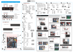
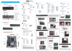
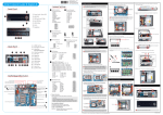
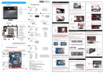
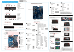
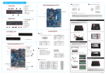
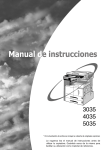
XH81V/XH81 Quick Guide【 English 】 __p Front Panel A. Begin Installation Jumper Settings C1 F1.Power Switch / Power LED F3 F2.HDD LED C2 F3.ODD and Front I/O Bay F2 F4 F4.Slim ODD Bay F5.USB3.0 Ports C3 F6.USB2.0 Ports F8.Headphone F5 F6 F7 F8 F6 C4 XH81 F6 F7 F8 F6 F1 Back Panel B5 B2 B1 B3 B4 B6 B8 B7 B9 B12 B10 C5 F2 B11 B1.DC Power Port B2.Kensington® Lock Port B3.COM1 Port (RS232/RS422/RS485) B4.COM2 Port (RS232) B5.DisplayPort B6.HDMI Port B7.Clear CMOS B8.LAN Ports B9.USB2.0 Ports B10.Mic-In Port B11.Line-Out Port B12.Line-In Port COM (x2) Ports C1 Front Audio Header-JP2 C2 USB Header-USB1 Serial ATA-SATA 1,2,3 SATA1,SATA2: Blue, 6Gbit/s port SATA3: Orange, 3Gbit/s port PCI-Express x1 Slot C3 TPM Header (LPC)-TPM1 LGA1150 Package CPU Socket Support RS232 Back panel C5 Independent External Power 12V/5V-JP1 10 8 6 4 2 4 6 8 10 Please do not apply excess amount of thermal paste. 1 6=RI8=LAD2 10=LAD1 12=GND 14=PCH_PME16=SERIRQ 18=CLKRUN_NC 20=SUS_CLK 3 5 7 1 2 3 4 5 6 7 8 9 10 11 12 13 14 15 16 17 18 19 20 9 4. Slide the rack downward and forward and refasten it using the two screws. 8. Screw the ICE module to the mainboard. Note to press down on the opposite diagonal corner while tightening each screw. 1 3. Unfasten the racks mount screws and remove the racks. 1 3 4 2 5. Connect the ODD cable and power cable to optical drive. Fan Connector C. Memory Module Installation 1. Locate the SODIMM slot on the mainboard. FFC Connector for Front Panel (JP5) 2=+5VS 6=U3_RX1P 10=U3_TX1P 14=USB8_P 18=+5VS 22=GND 26=GND 30=GND If you are installing the XH81 ODD, remove the front bay cover first. 3=+5VS 7=GND 11=GND 15=+5VS 19=U3_RX2N 23=U3_TX2N 27=USB9_N 2. Align the notch of the memory module with the one of the memory slot. 4=+5VS 8=GND 12=GND 16=+5VS 20=U3_RX2P 24=U3_TX2P 28=USB9_P Slimline SATA Cable SODIMM slot notch ODD Rack HDD Rack B. CPU and ICE Module Installation Support RS232 Back panel Independent External Power 12V / 5V (JP1) 1. Unfasten the four ICE module attachment screws. Rotating the fastener along the direction of arrow is to remove the ICE module, on the contrary, is to install. 1 3. Gently insert the module into the slot in a 45-degree angle. 4. Carefully push down the memory module until it snaps into the locking mechanism. 3 7. Connect the Serial ATA and power cables to the HDD. 1 2=COM_-XRI1 4=COM_-XRI2 6=+5V 8=COM2_PWR 10=+12V 10 9 8 7 6 5 4 3 2 1 4 6. Place the HDD in the rack and secure with the four screws from the side. Serial ATA Cable 2 Serial ATA Power Cable 2 45-degree angle Fan Connector C6 C7 SATA Power (5V)(PW2) 1=GND 2=GND 3=+5V 4=+5V 4 3 2 1 SATA Power (12V)(PW1) 1=GND 2=---3=+12V 1 2 3 Please note this 1150 pin socket bends easily. Always apply extreme care and little force when installing a CPU and limit the number of times you remove or exchange it. Before installation, make sure to turn off the computer and unplug the power cord from the mains to avoid damage. Follow the steps below to correctly install the CPU into the motherboard CPU socket. 3. First unlock and raise the socket lever. 2 1 1=GND 2=+12V 3=FANIO1 4=FANPWM1 2=PWRLED 4=GND 6=PWRSW8=GND 2 4 1 3 6 5 Latch 8. Slide the rack in the chassis and refasten the two screws. 5. Repeat the above steps to install additional memory modules, if required. 1 2 D. Component Installation 3 4 Front Panel Connector (JP3) 1=HDLEDPWR 3=-SATALED 5=RST_SW- 7=GND 9=--- Latch C9 FAN Connector (CPU_FAN1) AC BACK AUTO PWR-ON (JP4) 3 4. Lift the metal load plate on the CPU socket. Tear off the protective membrane from the bottom of ICE module. Remove the protective socket mylar from the CPU socket. 1. Install the Mini PCIE card into the Mini PCIE slot and secure with screws. 8 10 7 9 Remove the protective membrane Metal load plate Intel H81 Chipset SATA Power (5V)-PW2 SATA Power (12V)-PW1 C6 C7 Mini PCIE Slots Safety Information Read the following precautions before setting up a Shuttle XPC. CAUTION DDR3 SODIMM slots AC BACK AUTO PWR-ON-JP4 C8 Fan Connector-CPU_FAN1 C9 FFC Connector for Front Panel-JP5 Retention tab 2 Incorrectly replacing the battery may damage this computer. Replace only with the same or equivalent as recommended by Shuttle. Dispose of used batteries according to the manufacturer's instructions. Laser compliance statement C4 Thermal Paste application area Load lever 2 3. Place the slimline DVD drive in the rack and fasten it with the four screws from the sides. 2. Remove the ICE module from the chassis and put it aside. C10 DC Power Port 1 Metal load plate 2. Slide the cover backwards and upwards. VGA Connector-CN6 Mic-In/ Line-Out/ Line-In Ports 3 2=GND 1=RTCRST2=GND LAN (x2) & USB2.0 (x4) Ports 5 2=5V_USB 4=USB B6=USB B+ 8=GND 10=GND 1=-XRI1 3=-XRI2 5=+5V 7=COM1_PWR 9=+12V Motherboard Illustration DisplayPort & HDMI Ports 7 JUMP1 Connector Pin 1 and Pin 2 = RI1 Signal. JUMP2 Connector Pin 3 and Pin 4 = RI2 Signal. IF JUMP1 Connector Pin 5 and Pin 7 = RI1 is +5V IF JUMP2 Connector Pin 6 and Pin 8 = RI2 is +5V IF JUMP1 Connector Pin 7 and Pin 9 = RI1 is 12V IF JUMP2 Connector Pin 8 and Pin 10 = RI2 is 12V C8 Clear CMOS Button 9 TPM Header (LPC) (TPM1) 1=+5VS 5=U3_RX1N 9=U3_TX1N 13=USB8_N 17=+5VS 21=GND 25=GND 29=GND F4 F5 2=AGND 4=FP_AUDIO-JD 6=MIC-JD(AGND) 8=----10=HP-JD(AGND) 1=LPC_33M 3=LFRAME- 5=SIORST- 7=LAD3 9=+3.3V 11=LAD0 13=LPC_48M 15=+3.3VS 17=GND 19=PD#_NC F7.Mic-In 1. Unscrew the two thumbscrews of the chassis cover. USB Header (USB1) 1=5V_USB 3=USB A- 5=USB A+ 7=GND 9=NC 7. Spread thermal paste evenly on the CPU surface. For safety reasons, please ensure that the power cord is disconnected before opening the case. Front Audio Header (JP2) 1=MIC_L_C 3=MIC_R_C 5=HP_R_C 7=Sense B 9=HP_L_C F1 XH81V 6. Close the metal load plate, lower the CPU socket lever and lock in place. Front Panel Connector-JP3 C10 E. Complete DO NOT touch socket contacts. To protect the CPU socket, always replace the protective socket cover when the CPU is not installed. 5. Orientate the CPU and socket and please align the CPU notches with the socket alignment keys. Make sure the CPU is perfectly horizontal, insert it into the socket. CAUTION: INVISIBLE LASER RADIATION WHEN OPEN. AVOID EXPOSURE TO BEAM. 2. Untie all cables for easier installation. Triangle Pin1 Marking on the CPU The optical disc drive in this PC is a laser product. The drive's classification label is located on the drive. CLASS 1 LASER PRODUCT 1. Replace the cover and refasten the thumbscrews. Socket 1150 CPU Notch on the CPU/ Alignment Key of the CPU Socket Please be aware of the CPU orientation, DO NOT force the CPU into the socket to avoid bending of pins on the socket and damage of CPU! LThe product’s colour and specifications may vary from the actually shipping product. Purse lock 2 . Complete. Please load the optimized BIOS settings. 53R-XH8103-H001