1
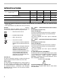
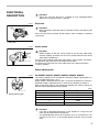
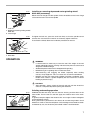
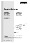
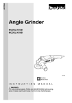
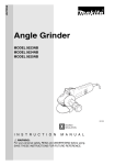
ENGLISH
Angle Grinder
MODEL 9560C
MODEL 9560CV
MODEL 9563C
MODEL 9563CV
MODEL 9561C
MODEL 9561CV
MODEL 9564C
MODEL 9564CV
MODEL 9562C
MODEL 9562CV
MODEL 9565C
MODEL 9565CV
001005
DOUBLE
INSULATION
I N S T R U C T I O N
M A N U A L
WARNING:
For your personal safety, READ and UNDERSTAND before using.
SAVE THESE INSTRUCTIONS FOR FUTURE REFERENCE.
SPECIFICATIONS
Depressed center wheel diameter
Spindle thread
100 mm M10
9560C
9563C
9560CV
9563CV
115 mm M14
9561C
9564C
9561CV
9564CV
125 mm M14
9562C
9565C
9562CV
9565CV
-1
No load speed (min )
11,000
11,000
2,800 - 11,000
2,800 - 11,000
Overall length
289 mm
299 mm
289 mm
299 mm
Net weight
1.7 kg
1.8 kg
1.7 kg
1.8 kg
Safety class
/II
• Due to our continuing programme of research and development, the specifications herein are subject to change
without notice.
• Note: Specifications may differ from country to country.
Symbols
END202-2
The following show the symbols used for the tool. Be
sure that you understand their meaning before use.
...................Read instruction manual.
...................DOUBLE INSULATION
.....................Wear safety glasses.
..................Only for EU countries
Do not dispose of electric equipment
together with household waste material!
In observance of European Directive
2002/96/EC on waste electric and
electronic equipment and its implementation in accordance with
national law, electric equipment that
have reached the end of their life
must be collected separately and
returned to an environmentally compatible recycling facility.
Intended use
The tool is intended for grinding, sanding and cutting of
metal and stone materials without the use of water.
Power supply
The tool should be connected only to a power supply of
the same voltage as indicated on the nameplate, and
can only be operated on single-phase AC supply. They
are double-insulated in accordance with European
Standard and can, therefore, also be used from sockets
without earth wire.
2
For Model 9560C/9560CV/9561C/9561CV/9562C/
9562CV
For European countries only
Noise and Vibration
The typical A-weighted sound pressure level is 83 dB (A).
The noise level under working may exceed 85 dB (A).
– Wear ear protection. –
The typical weighted root mean square acceleration
value is 4 m/s2.
For Model 9563C/9563CV/9564C/9564CV/9565C/
9565CV
For European countries only
Noise and Vibration
The typical A-weighted sound pressure level is 83 dB (A).
The noise level under working may exceed 85 dB (A).
– Wear ear protection. –
The typical weighted root mean square acceleration
value is 5 m/s2.
EC-DECLARATION OF CONFORMITY
We declare under our sole responsibility that this product
is in compliance with the following standards of standardized documents, HD400, EN50144, EN55014,
EN61000 in accordance with Council Directives, 73/23/
EEC, 89/336/EEC, 98/37/EC.
Yasuhiko Kanzaki CE 2003
Director
MAKITA INTERNATIONAL EUROPE LTD.
Michigan Drive, Tongwell, Milton Keynes, Bucks MK15
8JD, ENGLAND
SAFETY INSTRUCTIONS
ENA001-2
WARNING:
When using electric tools, basic safety precautions, including the following,
should always be followed to reduce the risk of fire, electric shock and
personal injury. Read all these instructions before operating this product
and save these instructions.
For safe operations:
1.
Keep work area clean.
Cluttered areas and benches invite injuries.
2.
Consider work area environment.
Do not expose power tools to rain. Do not use
power tools in damp or wet locations. Keep work
area well lit. Do not use power tools where there is
risk to cause fire or explosion.
Guard against electric shock.
Avoid body contact with earthed or grounded surfaces (e.g. pipes, radiators, ranges, refrigerators).
Keep children away.
Do not let visitors touch the tool or extension cord.
All visitors should be kept away from work area.
Store idle tools.
When not in use, tools should be stored in a dry,
high or locked up place, out of reach of children.
Do not force the tool.
It will do the job better and safer at the rate for which
it was intended.
Use the right tool.
Do not force small tools or attachments to do the job
of a heavy duty tool. Do not use tools for purposes
not intended; for example, do not use circular saws
to cut tree limbs or logs.
Dress properly.
Do not wear loose clothing or jewellery, they can be
caught in moving parts. Rubber gloves and non-skid
footwear are recommended when working outdoors.
Wear protecting hair covering to contain long hair.
Use safety glasses and hearing protection.
Also use face or dust mask if the cutting operation is
dusty.
Connect dust extraction equipment.
If devices are provided for the connection of dust
extraction and collection facilities ensure these are
connected and properly used.
Do not abuse the cord.
Never carry the tool by the cord or yank it to disconnect it from the socket. Keep the cord away from
heat, oil and sharp edges.
Secure work.
Use clamps or a vice to hold the work. It is safer
than using your hand and it frees both hands to
operate the tool.
Do not overreach.
Keep proper footing and balance at all times.
Maintain tools with care.
Keep cutting tools sharp and clean for better and
safer performance. Follow instructions for lubrica-
3.
4.
5.
6.
7.
8.
9.
10.
11.
12.
13.
14.
15.
16.
17.
18.
19.
20.
21.
22.
tion and changing accessories. Inspect tool cord
periodically and if damaged have it repaired by an
authorized service facility. Inspect extension cords
periodically and replace, if damaged. Keep handles
dry, clean and free from oil and grease.
Disconnect tools.
When not in use, before servicing and when changing accessories such as blades, bits and cutters.
Remove adjusting keys and wrenches.
Form the habit of checking to see that keys and
adjusting wrenches are removed from the tool
before turning it on.
Avoid unintentional starting.
Do not carry a plugged-in tool with a finger on the
switch. Ensure switch is off when plugging in.
Use outdoor extension leads.
When tool is used outdoors, use only extension
cords intended for outdoor use.
Stay alert.
Watch what you are doing. Use common sense. Do
not operate tool when you are tired.
Check damaged parts.
Before further use of the tool, a guard or other part
that is damaged should be carefully checked to
determine that it will operate properly and perform
its intended function. Check for alignment of moving
parts, free running of moving parts, breakage of
parts, mounting and any other conditions that may
affect its operation. A guard or other part that is
damaged should be properly repaired or replaced
by an authorized service center unless otherwise
indicated in this instruction manual. Have defective
switches replaced by an authorized service facility.
Do not use the tool if the switch does not turn it on
and off.
Warning.
The use of any accessory or attachment, other than
those recommended in this instruction manual or
the catalog, may present a risk of personal injury.
Have your tool repaired by a qualified person.
This electric tool is in accordance with the relevant
safety requirements. Repairs should only be carried
out by qualified persons using original spare parts,
otherwise this may result in considerable danger to
the user.
3
ADDITIONAL SAFETY RULES
1.
Always use eye and ear protection. Other personal protective equipment such as dust mask,
gloves, helmet and apron should be worn.
2.
Always be sure that the tool is switched off and
unplugged before carrying out any work on the
tool.
3.
Keep guards in place.
4.
Use only wheels with correct size and wheels
having a maximum operating speed at least as
high as the highest No Load Speed marked on
the tool’s nameplate. When using depressed
center wheels, be sure to use only fiberglassreinforced wheels.
ENB031-6
13. Hold the tool firmly.
14. Keep hands away from rotating parts.
15. Make sure the wheel is not contacting the workpiece before the switch is turned on.
16. Use the specified surface of the wheel to perform the grinding.
17. Do not use cutting off wheel for side grinding.
18. Watch out for flying sparks. Hold the tool so that
sparks fly away from you and other persons or
flammable materials.
19. Pay attention that the wheel continues to rotate
after the tool is switched off.
5.
Check the wheel carefully for cracks or damage
before operation. Replace cracked or damaged
wheel immediately.
20. Do not touch the workpiece immediately after
operation; it may be extremely hot and could
burn your skin.
6.
Observe the instructions of the manufacturer for
correct mounting and use of wheels. Handle and
store wheels with care.
21. Position the tool so that the power cord always
stays behind the machine during operation.
7.
Do not use separate reducing bushings or adaptors to adapt large hole abrasive wheels.
8.
Use only flanges specified for this tool.
9.
Do not damage the spindle, the flange (especially the installing surface) or the lock nut.
Damage to these parts could result in wheel
breakage.
10. For tools intended to be fitted with threaded
hole wheel, ensure that the thread in the wheel
is long enough to accept the spindle length.
11. Before using the tool on an actual workpiece,
test run the tool at the highest no load speed for
at least 30 seconds in a safe position. Stop
immediately if there is any vibration or wobbling
that could indicate poor installation or a poorly
balanced wheel. Check the tool to determine the
cause.
12. Check that the workpiece is properly supported.
22. If working place is extremely hot and humid, or
badly polluted by conductive dust, use a shortcircuit breaker (30 mA) to assure operator
safety.
23. Do not use the tool on any materials containing
asbestos.
24. Do not use water or grinding lubricant.
25. Ensure that ventilation openings are kept clear
when working in dusty conditions. If it should
become necessary to clear dust, first disconnect the tool from the mains supply ( use non
metallic objects ) and avoid damaging internal
parts.
26. When use cut-off wheel, always work with the
dust collecting wheel guard required by domestic regulation.
27. Cutting discs must not be subjected to any lateral pressure.
SAVE THESE INSTRUCTIONS
4
FUNCTIONAL
DESCRIPTION
•
002978
CAUTION:
Always be sure that the tool is switched off and unplugged before
adjusting or checking function on the tool.
Shaft lock
CAUTION:
Never actuate the shaft lock when the spindle is moving. The tool may be
damaged.
Press the shaft lock to prevent spindle rotation when installing or removing
accessories.
1
•
1. Shaft lock
001035
Switch action
1
CAUTION:
Before plugging in the tool, always check to see that the slide switch
actuates properly and returns to the “OFF” position when the rear of the
slide switch is depressed.
To start the tool, slide the slide switch toward the “I (ON)” position. For continuous operation, press the front of the slide switch to lock it.
To stop the tool, press the rear of the slide switch, then slide it toward the
“O (OFF)” position.
O
•
1. Slide switch
Speed adjusting dial
001046
For 9560CV, 9561CV, 9562CV, 9563CV, 9564CV, 9565CV
The rotating speed can be changed by turning the speed adjusting dial to a
given number setting from 1 to 5.
Higher speed is obtained when the dial is turned in the direction of number 5.
And lower speed is obtained when it is turned in the direction of number 1.
Refer to the below table for the relationship between the number settings on
the dial and the approximate rotating speed.
2
C00025
1
1. Speed adjusting dial
•
•
Number
min-1 (R.P.M.)
1
2,800
2
4,000
3
6,500
4
9,000
5
11,000
CAUTION:
If the tool is operated continuously at low speeds for a long time, the
motor will get overloaded and heated up.
The speed adjusting dial can be turned only as far as 5 and back to 1. Do
not force it past 5 or 1, or the speed adjusting function may no longer
work.
5
The tools equipped with electronic function are easy to operate because of the
following features.
• Electronic constant speed control
Possible to get fine finish, because the rotating speed is kept constantly
even under the loaded condition.
• Soft start feature
Soft start because of suppressed starting shock.
• Overload protector
When the tool would be employed over the admissible load, it will stop
automatically to protect the motor and wheel. When the load will come to
the admissible level again, the tool can be started automatically.
ASSEMBLY
•
002979
CAUTION:
Always be sure that the tool is switched off and unplugged before
carrying out any work on the tool.
Installing side grip (handle)
CAUTION:
• Always be sure that the side grip is installed securely before operation.
Screw the side grip securely on the position of the tool as shown in the figure.
002980
1
Installing or removing wheel guard
CAUTION:
The wheel guard must be fitted on the tool so that the closed side of the
guard always points toward the operator.
Loosen the lever on the wheel guard. Mount the wheel guard with the protrusion on the wheel guard band aligned with the notch on the bearing box. Then
rotate the wheel guard around 180 degrees. Tighten the lever to fasten the
wheel guard. If the lever is too tight or too loosen to fasten the wheel guard,
loosen or tighten the screw to adjust the tightening of the wheel guard band.
To remove wheel guard, follow the installation procedure in reverse.
•
2
3
4
1.
2.
3.
4.
Wheel guard
Bearing box
Screw
Lever
002981
1
1. Screw
6
001071
1
Installing or removing depressed center grinding wheel/
Multi-disc (accessory)
Mount the inner flange onto the spindle. Fit the wheel/disc on the inner flange
and screw the lock nut onto the spindle.
2
3
1. Lock nut
2. Depressed center grinding wheel/
Multi-disc
3. Inner flange
001084
1
To tighten the lock nut, press the shaft lock firmly so that the spindle cannot
revolve, then use the lock nut wrench and securely tighten clockwise.
To remove the wheel, follow the installation procedure in reverse.
2
1. Lock nut wrench
2. Shaft lock
OPERATION
•
•
•
•
•
•
WARNING:
It should never be necessary to force the tool. The weight of the tool
applies adequate pressure. Forcing and excessive pressure could cause
dangerous wheel breakage.
ALWAYS replace wheel if tool is dropped while grinding.
NEVER bang or hit grinding disc or wheel onto work.
Avoid bouncing and snagging the wheel, especially when working
corners, sharp edges etc. This can cause loss of control and kickback.
NEVER use tool with wood cutting blades and other sawblades. Such
blades when used on a grinder frequently kick and cause loss of control
leading to personal injury.
CAUTION:
After operation, always switch off the tool and wait until the wheel has
come to a complete stop before putting the tool down.
Grinding and sanding operation
002983
A
B
ALWAYS hold the tool firmly with one hand on housing and the other on the
side handle. Turn the tool on and then apply the wheel or disc to the workpiece.
In general, keep the edge of the wheel or disc at an angle of about 15 degrees
to the workpiece surface.
During the break-in period with a new wheel, do not work the grinder in the B
direction or it will cut into the workpiece. Once the edge of the wheel has been
rounded off by use, the wheel may be worked in both A and B direction.
7
MAINTENANCE
002985
1
2
1. Exhaust vent
2. Inhalation vent
CAUTION:
Always be sure that the tool is switched off and unplugged before
attempting to perform inspection or maintenance.
The tool and its air vents have to be kept clean. Regularly clean the tool’s air
vents or whenever the vents start to become obstructed.
To maintain product SAFETY and RELIABILITY, repairs, carbon brush inspection and replacement, any other maintenance or adjustment should be performed by Makita Authorized Service Centers, always using Makita
replacement parts.
•
ACCESSORIES
CAUTION:
These accessories or attachments are recommended for use with your Makita tool specified in this manual. The
use of any other accessories or attachments might present a risk of injury to persons. Only use accessory or
attachment for its stated purpose.
If you need any assistance for more details regarding these accessories, ask your local Makita service center.
•
•
•
•
•
•
•
8
Wheel guard (Wheel cover)
Inner flange
Depressed center wheels
Lock nut (For depressed center wheel)
Rubber pad
Abrasive discs
•
•
•
•
•
•
Lock nut (For abrasive disc)
Lock nut wrench
Wire cup brush
Wire bevel brush 85
Side Grip
Dust collecting wheel guard
Memo
9
Memo
10
Memo
11
Makita Corporation Anjo, Aichi, Japan
884311E225