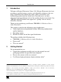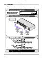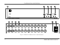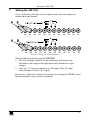
1
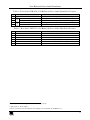
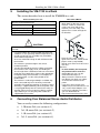
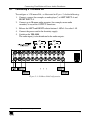
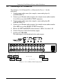
Kramer Electronics, Ltd.
Preliminary
USER MANUAL
Model:
VM-1120
1:10 Balanced Stereo Audio Distributor
Contents
Contents
1
2
2.1
3
4
5
6
6.1
6.2
6.3
6.4
7
8
Introduction
Getting Started
Quick Start
Overview
Your Balanced Stereo Audio Distributor
Installing the VM-1120 in a Rack
Connecting Your Balanced Stereo Audio Distributor
Connecting a 1:20 Mono DA
Connecting a 2x1:10 Mono DA
Connecting a 1:10 Stereo DA
Connecting a 2x1:5 Stereo DA
Setting the VM-1120
Technical Specifications
1
1
2
3
3
6
6
7
8
9
10
11
12
Figures
Figure 1: VM-1120 1:10 Balanced Stereo Audio Distributor
Figure 2: 1:20 Mono DA Configuration
Figure 3: 2x1:10 Mono DA Configuration
Figure 4: 1:10 Stereo DA Configuration
Figure 5: 2x1:5 Stereo DA Configuration
Figure 6: Using the Selector Button
4
7
8
9
10
11
Tables
Table 1: Front Panel VM-1120 1:10 Balanced Stereo Audio Distributor Features
Table 2: Rear Panel VM-1120 1:10 Balanced Stereo Audio Distributor Features
Table 3: VM-1120 Technical Specifications
5
5
12
i
Introduction
1
Introduction
Welcome to Kramer Electronics! Since 1981, Kramer Electronics has been
providing a world of unique, creative, and affordable solutions to the vast
range of problems that confront the video, audio, presentation, and
broadcasting professional on a daily basis. In recent years, we have
redesigned and upgraded most of our line, making the best even better! Our
1,000-plus different models now appear in 11 groups1 that are clearly
defined by function.
Thank you for purchasing your Kramer VM-1120 1:10 Balanced Stereo
Audio Distributor.
This product is ideal for the following typical applications:
Audio duplication and production studios, delivering undiminished
quality duplicates
Recording studios
Broadcast studios for on-line signal distribution
The package includes the following items:
VM-1120 1:10 Balanced Stereo Audio Distributor
Power cord2
This user manual3
2
Getting Started
We recommend that you:
Unpack the equipment carefully and save the original box and
packaging materials for possible future shipment
Review the contents of this user manual
Use Kramer high-performance high-resolution cables4
1 GROUP 1: Distribution Amplifiers; GROUP 2: Switchers and Matrix Switchers; GROUP 3: Control Systems;
GROUP 4: Format/Standards Converters; GROUP 5: Range Extenders and Repeaters; GROUP 6: Specialty AV Products;
GROUP 7: Scan Converters and Scalers; GROUP 8: Cables and Connectors; GROUP 9: Room Connectivity;
GROUP 10: Accessories and Rack Adapters; GROUP 11: Sierra Products
2 We recommend that you use only the power cord supplied with this device
3 Download up-to-date Kramer user manuals from our Web site at http://www.kramerelectronics.com
4 The complete list of Kramer cables is on our Web site at http://www.kramerelectronics.com
1
Getting Started
2.1
Quick Start
This quick start chart summarizes the basic setup and operation steps.
2
KRAMER: SIMPLE CREATIVE TECHNOLOGY
Overview
3
Overview
The VM-1120 is a high performance balanced stereo audio DA (distribution
amplifier) using XLR connectors that includes:
Front panel output level trimmer controls
Active J-FET amplifying circuitry that ensures hum-free, fullbandwidth operation
A high-power discrete buffering system providing excellent
performance
You can configure your VM-1120 as a mono DA (2x1:10 or 1:20) or as a
stereo DA (2x1:5 or 1:10).
Achieving the best performance means:
Connecting only good quality connection cables, thus avoiding
interference, deterioration in signal quality due to poor matching,
and elevated noise levels (often associated with low quality
cables)
Avoiding interference from neighboring electrical appliances that
may adversely influence signal quality
Positioning your Kramer VM-1120 in a location free from
moisture and away from excessive sunlight and dust
4
Your Balanced Stereo Audio Distributor
Figure 1 illustrates the front and rear panels of the VM-1120. Table 1 and
Table 2 define the front and rear panels of the VM-1120, respectively.
3
Your Balanced Stereo Audio Distributor
Figure 1: VM-1120 1:10 Balanced Stereo Audio Distributor
4
KRAMER: SIMPLE CREATIVE TECHNOLOGY
Your Balanced Stereo Audio Distributor
Table 1: Front Panel VM-1120 1:10 Balanced Stereo Audio Distributor Features
5
Feature
Power LED
1:10 / 2x1:5 Button
Level B and A Trimmers
RIGHT LEFT
#
1
2
3
4
1:10 / 2x1:5 Button
Level B and A Trimmers
Function
Illuminates when the unit is powered on
1
2
Push in to select 2x1:5 , release to select 1:10
3
Adjusts the output signal level for OUTPUTS A and B
1
2
Push in to select 2x1:5 , release to select 1:10
3
Adjusts the output signal level for OUTPUTS A and B
Table 2: Rear Panel VM-1120 1:10 Balanced Stereo Audio Distributor Features
#
6
7
8
9
10
11
Feature
INPUT A XLR Female Connector
INPUT B XLR Female Connector
OUT A XLR Male Connector
OUT B XLR Male Connector
Power Connector with Fuse
Power Switch
Function
Connects to the source A
Connects to the source B
Connects to the acceptor A (from 1 to 5)
Connects to the acceptor B (from 1 to 5)
230V AC, 50/60Hz, (115V AC, U.S.A.) power inlet
Turns the unit ON and OFF
1 Splits inputs A and B to outputs 1A-5A and 1B-5B, respectively
2 Splits input A to all 10 outputs
3 Insert a screwdriver into the small hole and carefully rotate it, trimming the OUTPUT level
5
Installing the VM-1120 in a Rack
5
Installing the VM-1120 in a Rack
This section describes how to install the VM-1120 in a rack.
Before Installing in a rack
Before installing in a rack, be sure that the environment is
within the recommended range:
Operating temperature range +5 to +45 C (41 to 113 F)
Operating humidity range
10 to 90% RHL, non-condensing
Storage temperature range
-20 to +70 C (-4 to 158 F)
Storage humidity range
5 to 95% RHL, non-condensing
How to Rack Mount
To rack-mount a machine:
1. Attach both ear brackets to the
machine. To do so, remove the
screws from each side of the
machine (3 on each side), and
replace those screws through the
ear brackets.
CAUTION!!
When installing on a 19" rack, avoid hazards by taking
care that:
1. It is located within the recommended environmental
conditions, as the operating ambient temperature of a
closed or multi unit rack assembly may exceed the
room ambient temperature.
2. Once rack mounted, enough air will still flow around
the machine.
3. The machine is placed straight in the correct
horizontal position.
4. You do not overload the circuit(s). When connecting
the machine to the supply circuit, overloading the
circuits might have a detrimental effect on overcurrent
protection and supply wiring. Refer to the appropriate
nameplate ratings for information. For example, for
fuse replacement, see the value printed on the
product label.
5. The machine is earthed (grounded) in a reliable way
and is connected only to an electricity socket with
grounding. Pay particular attention to situations where
electricity is supplied indirectly (when the power cord
is not plugged directly into the socket in the wall), for
example, when using an extension cable or a power
strip, and that you use only the power cord that is
supplied with the machine.
6
2. Place the ears of the machine
against the rack rails, and insert the
proper screws (not provided)
through each of the four holes in the
rack ears.
Note that:
In some models, the front panel
may feature built-in rack ears
Detachable rack ears can be
removed for desktop use
Always mount the machine in the
rack before you attach any cables
or connect the machine to the
power
If you are using a Kramer rack
adapter kit (for a machine that is not
19"), see the Rack Adapters user
manual for installation instructions
(you can download it at:
http://www.kramerelectronics.com)
Connecting Your Balanced Stereo Audio Distributor
You can easily connect the following configurations:
1:20 mono DA (see section 6.1)
2x1:10 mono DA (see section 6.2)
1:10 stereo DA (see section 6.3)
2x1:5 stereo DA (see section 6.4)
6
KRAMER: SIMPLE CREATIVE TECHNOLOGY
Connecting Your Balanced Stereo Audio Distributor
6.1
Connecting a 1:20 Mono DA
To configure a 1:20 mono DA, as illustrated in Figure 2, do the following:
1. Connect a source (for example, an audio player1) to LEFT INPUT A and
RIGHT INPUT A.
2. Connect up to 20 mono audio acceptors (for example, mono audio
recorders) to any of the OUTPUT connectors.
3. Release the LEFT and RIGHT selector buttons 1:10/2x1:5 to select 1:10.
4. Connect the power cord to the electricity supply.
5. Switch on the VM-1120.
The audio input(s) is/are distributed to the audio outputs.
Figure 2: 1:20 Mono DA Configuration
1 With 2 identical outputs, or via a 1:2 splitter
7
Connecting Your Balanced Stereo Audio Distributor
6.2
Connecting a 2x1:10 Mono DA
To configure a 2x1:10 mono DA, as illustrated in Figure 3, do the
following:
1. Connect mono audio source (for example, a mono audio player A)
to LEFT INPUT A.
2. Connect up to 10 mono audio acceptors (for example, mono audio recorders
1A to 10A) to any of the LEFT OUTPUT connectors.
3. Connect mono audio source (for example, a mono audio player B)
to RIGHT INPUT A.
4. Connect up to 10 mono audio acceptors (for example, mono audio recorders
1B to 10B) to any of the RIGHT OUTPUT connectors.
5. Release the LEFT and RIGHT selector buttons 1:10/2x1:5 to select 1:10.
6. Connect the power cord to the electricity supply.
7. Switch on the VM-1120.
The audio input(s) is/are distributed to the audio outputs.
Figure 3: 2x1:10 Mono DA Configuration
8
KRAMER: SIMPLE CREATIVE TECHNOLOGY
Connecting Your Balanced Stereo Audio Distributor
6.3
Connecting a 1:10 Stereo DA
To configure a 1:20 stereo DA, as illustrated in Figure 4, do the following:
1. Connect a stereo audio source (for example, a stereo audio player) to LEFT
INPUT A and RIGHT INPUT A.
2. Connect up to 10 stereo audio acceptors (for example, stereo audio
recorders 1 to 10) to the LEFT and RIGHT channels of any of the
OUTPUT connectors.
3. Release the LEFT and RIGHT selector buttons 1:10/2x1:5 to select 1:10.
4. Connect the power cord to the electricity supply.
5. Switch on the VM-1120.
The audio input(s) is/are distributed to the audio outputs.
Figure 4: 1:10 Stereo DA Configuration
9
Connecting Your Balanced Stereo Audio Distributor
6.4
Connecting a 2x1:5 Stereo DA
To configure a 2x1:5 stereo DA, as illustrated in Figure 5, do the following:
1. Connect a stereo audio source (for example, a stereo audio player A) to
LEFT and RIGHT INPUT A.
2. Connect up to 5 stereo audio acceptors (for example, mono audio recorders
1A to 5A) to any of the LEFT and RIGHT A OUTPUT connectors.
3. Connect a stereo audio source (for example, a stereo audio player B) to
LEFT and RIGHT INPUT B.
4. Connect up to 5 stereo audio acceptors (for example, mono audio recorders
1B to 5B) to any of the LEFT and RIGHT B OUTPUT connectors.
5. Push IN the LEFT and RIGHT selector buttons 1:10/2x1:5 to select 2x1:5.
6. Connect the power cord to the electricity supply.
7. Switch on the VM-1120.
The audio input(s) is/are distributed to the audio outputs.
Figure 5: 2x1:5 Stereo DA Configuration
10
KRAMER: SIMPLE CREATIVE TECHNOLOGY
Setting the VM-1120
7
Setting the VM-1120
Figure 6 illustrates how the selector button works when two inputs are
connected to one channel.
Figure 6: Using the Selector Button
Note the following when using the VM-1120:
The left and right channels are not connected. Left inputs only
distribute to left outputs and right inputs only distribute to right
outputs
Only the “A” input can distribute to 10 outputs. The “B” input
only distributes to the 5 “B” outputs
If necessary, adjust the volume on the outputs by turning the LEVEL A and
B potentiometers using a small screwdriver.
11
Technical Specifications
8
Technical Specifications
The VM-1120 technical specifications are shown in Table 3:
1
Table 3: VM-1120 Technical Specifications
INPUTS:
OUTPUTS:
MAX. OUTPUT LEVEL:
BANDWIDTH (-3dB):
S/N RATIO:
CROSSTALK:
CONTROLS:
COUPLING:
AUDIO THD + NOISE:
AUDIO 2nd HARMONIC:
POWER SOURCE:
DIMENSIONS:
WEIGHT:
ACCESSORIES:
4 balanced audio +4dBu/50k on XLR (F) connectors
20 balanced audio +4dBu/50 on XLR (M) connectors
>26dBu
>100kHz
89.3dB
-78dB
Level (x4): -0.7dB to +5.1dB, mode selector switches
AC (input); DC (output)
0.081%
0.006%
230V AC, (115V AC U.S.A) 15VA
19" x 7" x 2U W, D, H, rack mountable
3.5kg (7.7lbs) approx
Power cord, rack ears
1 Specifications are subject to change without notice
12
KRAMER: SIMPLE CREATIVE TECHNOLOGY
LIMITED WARRANTY
Kramer Electronics (hereafter Kramer) warrants this product free from defects in material and workmanship under the
following terms.
HOW LONG IS THE WARRANTY
Labor and parts are warranted for seven years from the date of the first customer purchase.
WHO IS PROTECTED?
Only the first purchase customer may enforce this warranty.
WHAT IS COVERED AND WHAT IS NOT COVERED
Except as below, this warranty covers all defects in material or workmanship in this product. The following are not covered
by the warranty:
1. Any product which is not distributed by Kramer, or which is not purchased from an authorized Kramer dealer. If you are
uncertain as to whether a dealer is authorized, please contact Kramer at one of the agents listed in the Web site
www.kramerelectronics.com.
2. Any product, on which the serial number has been defaced, modified or removed, or on which the WARRANTY VOID
IF TAMPERED sticker has been torn, reattached, removed or otherwise interfered with.
3. Damage, deterioration or malfunction resulting from:
i) Accident, misuse, abuse, neglect, fire, water, lightning or other acts of nature
ii) Product modification, or failure to follow instructions supplied with the product
iii) Repair or attempted repair by anyone not authorized by Kramer
iv) Any shipment of the product (claims must be presented to the carrier)
v) Removal or installation of the product
vi) Any other cause, which does not relate to a product defect
vii) Cartons, equipment enclosures, cables or accessories used in conjunction with the product
WHAT WE WILL PAY FOR AND WHAT WE WILL NOT PAY FOR
We will pay labor and material expenses for covered items. We will not pay for the following:
1. Removal or installations charges.
2. Costs of initial technical adjustments (set-up), including adjustment of user controls or programming. These costs are the
responsibility of the Kramer dealer from whom the product was purchased.
3. Shipping charges.
HOW YOU CAN GET WARRANTY SERVICE
1. To obtain service on you product, you must take or ship it prepaid to any authorized Kramer service center.
2. Whenever warranty service is required, the original dated invoice (or a copy) must be presented as proof of warranty
coverage, and should be included in any shipment of the product. Please also include in any mailing a contact name,
company, address, and a description of the problem(s).
3. For the name of the nearest Kramer authorized service center, consult your authorized dealer.
LIMITATION OF IMPLIED WARRANTIES
All implied warranties, including warranties of merchantability and fitness for a particular purpose, are limited in duration to
the length of this warranty.
EXCLUSION OF DAMAGES
The liability of Kramer for any effective products is limited to the repair or replacement of the product at our option. Kramer shall
not be liable for:
1. Damage to other property caused by defects in this product, damages based upon inconvenience, loss of use of the product, loss
of time, commercial loss; or:
2. Any other damages, whether incidental, consequential or otherwise. Some countries may not allow limitations on how long an
implied warranty lasts and/or do not allow the exclusion or limitation of incidental or consequential damages, so the above
limitations and exclusions may not apply to you.
This warranty gives you specific legal rights, and you may also have other rights, which vary from place to place.
NOTE: All products returned to Kramer for service must have prior approval. This may be obtained from your dealer.
This equipment has been tested to determine compliance with the requirements of:
EN-50081:
EN-50082:
CFR-47:
"Electromagnetic compatibility (EMC);
generic emission standard.
Part 1: Residential, commercial and light industry"
"Electromagnetic compatibility (EMC) generic immunity standard.
Part 1: Residential, commercial and light industry environment".
FCC* Rules and Regulations:
Part 15: “ Radio frequency devices
Subpart B Unintentional radiators”
CAUTION!
Servicing the machines can only be done by an authorized Kramer technician. Any user who makes changes or
modifications to the unit without the expressed approval of the manufacturer will void user authority to operate the
equipment.
Use the supplied DC power supply to feed power to the machine.
Please use recommended interconnection cables to connect the machine to other components.
* FCC and CE approved using STP cable (for twisted pair products)
13
For the latest information on our products and a list of Kramer
distributors, visit our Web site: www.kramerelectronics.com
where updates to this user manual may be found.
We welcome your questions, comments and feedback.
Safety Warning:
Disconnect the unit from the power supply before
opening/servicing.
Caution
P/N: 2900- 001029
Rev: 3
Kramer Electronics, Ltd.
Web site: www.kramerelectronics.com
E-mail: [email protected]
P/N: 2900-001029 REV 3