1
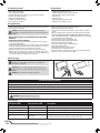
®
Instruction Manual
Bedienungsanleitung
Manuel d’utilisation
Manuale di Istruzioni
NOTICE
All instructions, warranties and other collateral documents are subject to change at the sole discretion of Horizon Hobby, LLC. For up-to-date product literature, visit
horizonhobby.com and click on the support tab for this product.
Meaning of Special Language
The following terms are used throughout the product literature to indicate various levels of potential harm when operating this product:
NOTICE: Procedures, which if not properly followed, create a possibility of physical property damage AND a little or no possibility of injury.
CAUTION: Procedures, which if not properly followed, create the probability of physical property damage AND a possibility of serious injury.
WARNING: Procedures, which if not properly followed, create the probability of property damage, collateral damage, and serious injury OR create a high probability of
superficial injury.
WARNING: Read the ENTIRE instruction manual to become familiar with the features of the product before operating. Failure to operate the product correctly
can result in damage to the product, personal property and cause serious injury.
This is a sophisticated hobby product. It must be operated with caution and common sense and requires some basic mechanical ability. Failure to operate this Product
in a safe and responsible manner could result in injury or damage to the product or other property. This product is not intended for use by children without direct
adult supervision. Do not use with incompatible components or alter this product in any way outside of the instructions provided by Horizon Hobby, LLC. This manual
contains instructions for safety, operation and maintenance. It is essential to read and follow all the instructions and warnings in the manual, prior to assembly, setup
or use, in order to operate correctly and avoid damage or serious injury.
Age Recommendation: Not for children under 14 years. This is not a toy.
Safety Precautions and Warnings
•Always keep a safe distance in all directions around your model to avoid collisions or injury. This model is controlled by a radio signal subject to interference
from many sources outside your control. Interference can cause momentary loss
of control.
•Always operate your model in open spaces away from full-size vehicles, traffic
and people.
•Always carefully follow the directions and warnings for this and any optional
support equipment (chargers, rechargeable battery packs, etc.).
•Always keep all chemicals, small parts and anything electrical out of the reach
of children.
•Always avoid water exposure to all equipment not specifically designed and
protected for this purpose. Moisture causes damage to electronics.
•Never place any portion of the model in your mouth as it could cause serious
injury or even death.
•Never operate your model with low transmitter batteries.
•Always keep aircraft in sight and under control.
•Always move the throttle fully down at rotor strike.
•Always use fully charged batteries.
•Always keep transmitter powered on while aircraft is powered.
•Always remove batteries before disassembly.
•Always keep moving parts clean.
•Always keep parts dry.
•Always let parts cool after use before touching.
•Always remove batteries after use.
•Never operate aircraft with damaged wiring.
•Never touch moving parts.
WARNING AGAINST COUNTERFEIT PRODUCTS: If you ever need to replace a Spektrum component found in a Horizon Hobby product, always purchase from
Horizon Hobby, LLC or a Horizon Hobby authorized dealer to ensure authentic high-quality Spektrum product. Horizon Hobby, LLC disclaims all support and
warranty with regards, but not limited to, compatibility and performance of counterfeit products or products claiming compatibility with DSM or Spektrum.
EN
2
®
Box Contents:
•
•
•
•
•
Blade 450 X
3S 11.1V 2200mAh 30C Li-Po Battery
DC Li-Po Balancing Charger
Spektrum DX6i Transmitter
4 AA Batteries
Table of Contents
First Flight Preparation . ....................................................................................... 4
Flying Checklist ................................................................................................... 4
Charging Warnings............................................................................................... 4
Battery Charging................................................................................................... 4
Low Voltage Cutoff (LVC)....................................................................................... 5
Installing the Transmitter Batteries . ..................................................................... 5
Transmitter Functions........................................................................................... 5
Transmitter Mode Conversion............................................................................... 5
Transmitter Setup................................................................................................. 6
Installing the Flight Battery................................................................................... 6
Transmitter and Receiver Binding.......................................................................... 7
Throttle Hold......................................................................................................... 7
Control Tests......................................................................................................... 7
Pre-Flight Checklist.............................................................................................. 8
Flying the Blade 450 X.......................................................................................... 8
Gyro Gain Adjustment........................................................................................... 9
Blade Helicopter Belt Tension................................................................................ 9
Post-Flight Inspections and Maintenance.............................................................. 9
AR7200BX Default Blade 450 X Setup................................................................. 10
AR7200BX Parameter Menu Tips........................................................................ 10
AR7200BX Fine-tuning and Adjustment............................................................... 11
Troubleshooting Guide........................................................................................ 11
Limited Warranty................................................................................................ 12
Warranty and Service Contact Information.......................................................... 12
FCC Information.................................................................................................. 13
IC Information..................................................................................................... 13
Compliance Information for the European Union.................................................. 13
Exploded Views................................................................................................... 50
Parts List............................................................................................................ 52
Optional Parts..................................................................................................... 54
Specifications
Length
34.3 in (870mm)
Tail Rotor Diameter
6.1 in (155mm)
Height
8.8 in (225mm)
Flying Weight
25.3 oz (717 g)
Main Rotor Diameter
28.5 in (725mm)
Components
Airframe
Blade® 450 X
Charger
DC Li-Po Balancing Charger
Motor
440H Brushless Outrunner, 4200Kv
Transmitter
Spektrum DX6i Transmitter
Receiver
Spektrum™ AR7200BX with BeastX Technology
Swash Servos
Digital Cyclic Servo 12 g Metal Gear
ESC
35-Amp Brushless ESC
Tail Servo
Digital Tail Servo 12 g Metal Gear
Battery
3S 11.1V 2200mAh 30C Li-Po
®
To register your product online, visit www.bladehelis.com
3
EN
First Flight Preparation
Flying Checklist
• Remove and inspect contents
• Begin charging the flight battery
• Install the flight battery in the helicopter (once it has been fully charged)
• Program your computer transmitter
• Bind your transmitter (BNF only)
• Familiarize yourself with the controls
• Find a suitable area for flying
❏❏Always turn the transmitter on first
❏❏Plug the flight battery into the lead from the ESC
❏❏Allow the ESC to initialize and arm properly
❏❏Fly the model
❏❏Land the model
❏❏Unplug the flight battery from the ESC
❏❏Always turn the transmitter off last
Charging Warnings
The Battery Charger (EFLC3115) included with your helicopter has been designed
to safely charge the Li-Po battery.
• Always charge batteries away from flammable materials.
• Always inspect the battery before charging.
• Always disconnect the battery after charging, and let the charger cool between
charges.
• Always constantly monitor the temperature of the battery pack while charging.
• ONLY USE A CHARGER SPECIFICALLY DESIGNED TO CHARGE LI-PO BATTERIES.
Failure to charge the battery with a compatible charger may cause a fire resulting
in personal injury and/or property damage.
• Never discharge Li-Po cells to below 3V under load.
• Never cover warning labels with hook and loop strips.
• Never leave charging batteries unattended.
• Never charge batteries outside recommended levels.
• Never charge damaged batteries.
• Never attempt to dismantle or alter the charger.
• Never allow minors to charge battery packs.
• Never charge batteries in extremely hot or cold places (recommended between
40–120° F or 5–49° C) or place in direct sunlight.
CAUTION: All instructions and warnings must be followed exactly.
Mishandling of Li-Po batteries can result in a fire, personal injury and/or
property damage.
• NEVER LEAVE THE POWER SUPPLY, CHARGER AND BATTERY UNATTENDED
DURING USE.
• NEVER CHARGE BATTERIES OVERNIGHT.
• By handling, charging or using the included Li-Po battery, you assume all risks
associated with lithium batteries.
• If at any time the battery begins to balloon or swell, discontinue use immediately. If
charging or discharging, discontinue and disconnect. Continuing to use, charge or
discharge a battery that is ballooning or swelling can result in fire.
• Always store the battery at room temperature in a dry area for best results.
• Always transport or temporarily store the battery in a temperature range of 40–
120º F (5–49° C). Do not store battery or model in a car or direct sunlight. If stored
in a hot car, the battery can be damaged or even catch fire.
Battery Charging
CAUTION: Charge only batteries that are cool to the touch and are not
damaged. Look at the battery to make sure it is not damaged e.g.,
swollen, bent, broken or punctured.
CAUTION: Only use a charger specifically designed to charge a Li-Po
battery. Failure to do so could result in fire causing injury or property
damage.
CAUTION: Never exceed the recommended charge rate.
The Battery Charging Process
1.Connect the charger to a 12V power source, noting proper polarity. 2.The CHARGE STATUS LED glows solid red.
3.Connect the battery balance lead to the charger. The balance connector is keyed to prevent reverse polarity.
4.The CELL STATUS LEDs glow solid green or yellow and the CHARGE STATUS LED glows solid red when the battery is charging.
5.Charging is complete when all LEDs glow solid red.
6.Always unplug the battery from the charger immediately upon completion of charging. CAUTION: Overcharging a battery can cause a fire.
LED Indications
EN
Cell Status LEDs
Charge Status LED
Instruction
Off
Red Solid
Battery charger is powered. Li-Po battery is not connected
Yellow
Red Solid
Li-Po battery is connected. Charger is balancing the battery pack cells
Green
Red Solid
Li-Po battery is connected and charging
Red
Red Solid
Li-Po battery is connected and charging is complete
Off
Blinking Red
No Li-Po battery connected: Voltage is outside the input voltage range
Li-Po battery connected: At least one battery cell voltage is below 2.6V
4
Low Voltage Cutoff (LVC)
The ESC will continuously lower power to the motor until complete shutdown when the battery reaches 9V under load. This helps prevent over-discharge of the
Li-Po battery. Land immediately when the ESC activates LVC. Continuing to fly after
LVC can damage the battery, cause a crash or both. Crash damage and batteries
damaged due to over-discharge are not covered under warranty.
Repeatedly flying the helicopter until LVC activates will damage the helicopter
battery.
Disconnect and remove the Li-Po battery from the aircraft after use to prevent
trickle discharge. During storage, make sure battery charge does not fall below 3V
per cell.
Installing the Transmitter Batteries
Replace transmitter batteries when the transmitter beeps and flashes a warning
screen.
1
2
Transmitter Functions
Function
A Antenna
B Throttle Cut
Mix/Throttle Hold (Mode 2)
C
Trainer/Bind (Mode 1)
Rudder Dual Rate (Mode 2)
D
Gear/Flight Mode (Mode 1)
E Aileron Dual Rate
Function
Function
Aileron/Elevator Stick (Mode 2)
F
Aileron/Throttle Stick (Mode 1)
Elevator Trim (Mode 2)
G
Throttle Trim (Mode 1)
H Aileron Trim
K Charge Port
L Rudder Trim
Throttle Trim (Mode 2)
M
Elevator Trim (Mode 1)
Throttle/Rudder Stick (Mode 2)
N
Elevator/Rudder Stick (Mode 1)
O Elevator Dual Rate
I Roller
J On/Off Switch
Function
Gear/Flight Mode (Mode 2)
P
Rudder Dual Rate (Mode 1)
Trainer/Bind (Mode 2)
Q
Mix/Throttle Hold (Mode 1)
R Flap/Gyro
S Trainer Port
T Battery Cover
A
Q
D
P
C
R
B
O
S
F
N
L
E
M
H
G
J
K
I
T
The transmitter comes with a thin clear plastic film applied to some front panels
for protection during shipping. Humidity and use may cause this film to come off.
Carefully remove this film as desired.
For more information on the transmitter, go to www.horizonhobby.com and click on
the support tab for the Spektrum DX6i to download the instruction manual.
Transmitter Mode Conversion
You can change transmitter modes between Mode 1 and Mode 2. This conversion
requires both a programming and a mechanical change.
4. Move the Aileron D/R switch forward and backward FOUR TIMES. A screen will
display Mode 1 and Mode 2.
5. Select the desired mode.
6. After you change the transmitter Mode in the Setup List, you will need to make
mechanical changes to the transmitter gimbals.
Programming set up
1. Power on the transmitter.
2. Press the roller, scroll to Setup List and press the roller to access the Setup
List.
3. Select Copy/Reset in the Setup List. When the Copy/Reset menu screen opens,
select Reset.
CAUTION: Always power off the transmitter and remove the batteries
before adjusting stick tension or friction straps. Not doing so could result
in property damage or injury.
5
EN
Mechanical Conversion
Mechanical conversion is required to change between Modes 1 and 2. The
mechanical conversion consists of the following steps:
Removing the Rear Case:
1. Power off the transmitter and remove the transmitter batteries.
2. Remove the six Phillips head screws that secure the rear transmitter case half.
3. Put the transmitter face down on a piece of foam or a towel and remove the
rear case.
the throttle gimbal. Tighten the opposite throttle strap to engage the desired
throttle ratchet.
Adjusting the Elevator Centering Screw:
When changing between Modes 1 and 2, you must adjust the elevator centering
screw.
1. Hold the Elevator or Throttle stick in the full up or full down position when you
are adjusting the elevator centering screw. Holding the gimbal stick reduces
the load on the elevator centering mechanism and makes it easier to adjust
the centering screw.
2. Locate the gimbal where the elevator centering spring is engaged. Use a
Phillips screwdriver to tighten the elevator centering screw. Tightening the
screw will disengage the centering spring.
3. Using a Phillips screwdriver, loosen the opposite elevator centering screw until
the lever engages.
CAUTION: Use care to not pull or disconnect any of the wires attached to
the back transmitter half.
Changing the Throttle Ratchet:
1. Locate the silver throttle friction straps on both gimbals.
2. To change the throttle ratchet, loosen the throttle strap so it does not touch
Transmitter Setup
Program your transmitter before attempting to bind or fly the helicopter.
SETUP LIST
Model Type
HELI
ADJUST LIST
Reverse
Swash Type
Timer
THRO N
AILE
N
Type: Down
ELEV
N
1 Servo 90 Degree Time: 4:00
RUDD R
Switch: Trainer
GYRO N
PITC
R
Switch
AILE
ELEV
RUDD
Dual Rate / Expo
Pos.
D/R Expo
0
100% INH
1
85% INH
0
100% INH
1
85% INH
0
100% INH
1
85% INH
Travel Adjust
THRO
AILE
ELEV
RUDD
GYRO
PITC
100%
100%
100%
100%
100%
100%
Sub-Trim*
THRO
AILE
ELEV
RUDD
GYRO
PITC
0
0*
0*
0*
0
0
* Never use sub-trims or trims on AILE, ELEV or RUDD channels with the AR7200BX.
Pos.
Gyro
Rate
SW-F. Mode
0
77.0% NORM
0
1
77.0% STUNT
0
NORM
STUNT
HOLD
Throttle Curve
L
2
3
0%
30% 60%
75%
75% 75%
10%
10% 10%
4
60%
75%
10%
H
60%
75%
10%
NORM
STUNT
HOLD
L
30%
0%
0%
Pitch Curve
2
3
40% 50%
25% 50%
25% 50%
Swash Mix
4
75%
75%
75%
H
100%
100%
100%
INHIBIT
Installing the Flight Battery
CAUTION: Make sure the flight battery does not come in contact with the
motor. Failure to do so will cause the motor, ESC and battery to overheat,
resulting in a crash causing property damage and injury.
1.Lower the throttle.
2.Power on the transmitter.
3.Center the throttle trim.
4.To allow the ESC to arm and to keep rotors from initiating at startup, turn on
throttle hold and normal flight mode before connecting the flight battery.
5.Attach hook material to the helicopter frame and loop material to the battery.
6.Install the flight battery on the helicopter frame. Secure the flight battery with a
hook and loop strap. Connect the battery cable to the ESC.
7.Do not move the helicopter until the AR7200BX initializes. The swashplate will
move up and down, indicating that the unit is ready. The AR7200BX will also
emit a solid BLUE Status LED when it is ready.
8.The helicopter motor will emit 2 tones, incdicating the ESC is armed.
CAUTION: Always disconnect the Li-Po battery from the aircraft
receiver when not flying to avoid over-discharging the battery. Batteries
discharged to a voltage lower than the lowest approved voltage may become
damaged, resulting in loss of performance and potential fire when batteries are
charged.
CAUTION: Always keep the power lead positioned AWAY from the
elevator servo. Failure to do so could cause the lead to get caught,
resulting in a crash causing property damage and injury.
EN
6
Transmitter and Receiver Binding
The transmitter comes prebound to the model. If you need to rebind, follow the directions below.
Binding Procedure
1. Insert the bind plug in the BND/DAT port on the receiver.
2. Connect the flight battery to the ESC. The H menu LED should be flashing, indicating the AR7200BX is in bind mode.
3. Move the throttle stick to the desired failsafe position (low throttle position in normal mode).
4. Power on the transmitter while holding the Trainer/Bind switch. Hold the Trainer/Bind switch until binding is complete. The system will connect within a few
seconds. Once connected, the H LED will turn off and the AR7200BX will start the initialization process.
5. When the initialization process is complete, menu LED H will turn OFF and the Status LED light will come ON solid BLUE.
6. Disconnect the flight battery and remove the bind plug from the AR7200BX. Store the bind plug in a convenient place.
WARNING: You must move the throttle to the LOW/OFF position during
binding. Failure to do so may cause the rotor blades to spin and the helicopter to lift during the AR7200BX initialization, which could result in damage to
property and injury.
NOTICE: Remove the bind plug to prevent the system from entering bind mode the
next time the power is turned on.
If you encounter problems, obey binding instructions and refer to transmitter
troubleshooting guide for other instructions. If needed, contact the appropriate
Horizon Product Support office.
Throttle Hold
Throttle hold only turns off the motor on an electric helicopter. You maintain pitch
and direction control.
The blades will spin if throttle hold is OFF. For safety, turn throttle hold ON any time
you need to touch the helicopter or check the direction controls.
Throttle hold is also used to turn off the motor if the helicopter is out of control, in
danger of crashing, or both.
Control Tests
CAUTION: You must complete the Rudder and Cyclic tests prior to flight. Failure to complete the tests ensuring the sensor directions are not reversed can cause
the helicopter to crash, resulting in property damage and injury.
Rudder
1. Power on the transmitter.
2. Turn TH HOLD ON and put transmitter in normal mode.
3. Connect the helicopter battery to the ESC.
4. Move the rudder stick to the right. The
tail rotor blades move as shown. If they
do not move as shown, reverse the rudder
channel in the transmitter (refer to your
transmitter manual for instructions).
5. Release the rudder control. Manually turn
the helicopter nose to the left. The tail rotor blades automatically move as shown.
If they do not move as shown, refer to the
AR7200BX manual for information on reversing the tail sensor direction (Setup menu point F).
NOTICE: Do not allow the helicopter to move until the Status LED is solid blue and
all menu LEDs are OFF. The gyro will not operate correctly if the helicopter moves
before the Status LED is solid blue.
Cyclic
When using a flybarless rotor head, you are controlling rotational rates while the
AR7200BX controls the servos. You are not directly controlling the servos with the
transmitter.
It is normal for the swashplate to slowly move back to its original position
after a stick input and for the servos to not move at the same speed as your
control sticks.
1. Tilt the helicopter forward. The swashplate should tilt backward.
2. Tilt the helicopter backward. The swashplate should tilt forward.
3. Roll the helicopter left. The swashplate should roll right.
4. Roll the helicopter right. The swashplate should roll left.
5. If the swashplate does not move in the correct direction, you will need to
reverse the cyclic sensor direction. Refer to the AR7200BX manual for more
information (Setup menu point M).
7
EN
Cyclic and Collective Control Test
Turn on Throttle Hold when doing the control tests.
Elevator
Side View
Side View
Aileron
ail
ail
Rear View
Rear View
Rear View
Rear View
Collective Pitch
ail
Motor
WARNING: Stay at least 30 feet (10 meters) away from the helicopter
when the motor is running. Do not attempt to fly the helicopter at this
time.
Place the helicopter outdoors on a clean, flat and level surface (concrete or
asphalt) free of obstructions. Always stay clear of moving rotor blades.
1. The motor beeps twice when the helicopter’s ESC arms properly. Before you
continue, confirm that TH HOLD is ON.
3. Ensure the throttle is lowered completely. Confirm the transmitter is still set
to normal flight mode. Turn throttle hold off at this time. Slowly increase the
throttle until the blades begin to spin. The main blades spin clockwise when
viewing the helicopter from the top. The tail rotor blades spin counterclockwise
when viewing the helicopter from the right-hand side.
WARNING: The motor will spin when throttle is increased while TH HOLD
is OFF.
2. Check the swashplate directions to ensure they are moving in the correct
direction. Please refer to the diagrams above for reference.
Pre-Flight Checklist
❏❏Check all screws and ensure that they are tight
❏❏Check belt tension and ensure that it is not too tight or too loose
❏❏Check main and tail blades to ensure they are not damaged
❏❏Check all links and make sure they move freely but do not pop off easily
❏❏Check that flight battery and transmitter battery are fully charged
❏❏Check all wires to ensure that they are not cut, pinched, or chaffed and are
properly secured
❏❏Check all wire connections
❏❏Check gears and make sure no teeth are missing
❏❏Do a complete control test
❏❏Check that servos are functioning properly
❏❏Check to make sure flight battery is properly secured
❏❏Check to make sure AR7200BX is properly secured
Flying the Blade 450 X
ail
EN
• Always keep aircraft in sight and under control
• Always turn on throttle hold at loss of control or rotor strike
• Always use fullly charged batteries
• Always keep transmitter powered on while aircraft is powered
• Always remove batteries before disassembly
• Always keep moving parts clean
• Always keep parts dry
ail
8
• Always let parts cool after use before touching
• Always remove batteries after use
• Always keep people and pets at least 30 feet away when the flight battery
is connected
• Never operate aircraft with damaged wiring
• Never touch moving parts
Consult local laws and ordinances before choosing a location
to fly your aircraft.
First flights should be performed in normal mode and low cyclic and rudder dual
rates until you are familiar with the flying manner of the Blade 450 X. Discover
the rates that fit your flying style.
Select a large, open area away from people and objects. Your first flights should
be outdoors in low-wind conditions. Always stay at least 30 feet (10 meters) away
from the helicopter when it is flying.
CAUTION: Always fly the helicopter with your back to the sun and the
wind to prevent loss of flight control.
The Blade 450 X is intended to be flown outdoors.
Landing
CAUTION: The Blade 450 X is intended for pilots with experience
flying aerobatic, collective pitch helicopters. The Blade 450 X is more
responsive than other Blade helicopters. If you are not an experienced 3D or
collective pitch helicopter pilot, do not attempt to fly this product.
Establish a low level hover. Deliberately lower the throttle until the helicopter
lands. Do not give any aileron, elevator or rudder commands when the helicopter
is landing.
When the helicopter is in stunt mode:
• The rotor head speed is constant.
• The main rotor will increase negative pitch as the throttle/collective stick is
moved from the middle stick position to the low stick position. Negative pitch
allows the helicopter to fly upside down and perform aerobatics.
Change between stunt and idle up modes in a hover with the throttle near the
hovering stick position. The helicopter may go up or down when you change between modes due to the
difference in the throttle and pitch curves.
Takeoff
Deliberately increase throttle and establish a hover at least 24” (0.6 meter) high,
outside of ground effect.
CAUTION: Do not give any aileron, elevator or rudder commands before
takeoff or the helicopter may crash during takeoff.
Flying
The helicopter lifts off the ground when the rotor head reaches a suitable speed.
Establish a low-level hover to verify proper operation of your helicopter. You must
not set any trim; the flybarless design of the Blade 450 X renders trim unnecessary. Setting trim or sub-trim can cause an unwanted drift or rotation of the
helicopter.
WARNING: Do not use wooden main blades with the Blade 450 X or injury and/or property damage could occur. Only use Blade 450 X approved
carbon fiber main blades.
Gyro Gain Adjustment
• If the tail wags or oscillates, lower the gain on the gyro.
• If the tail is drifting while hovering, increase the gain on the gyro.
On your transmitter’s gyro menu, decrease the gyro gain values a small amount
at a time until the helicopter is stable within a particular flight mode.
On your transmitter, increase the gyro gain values a small amount at a time until
the tail starts to wag/oscillate. Afterwards, reduce the gain until the tail stops
wagging/oscillating within a particular flight mode.
Blade Helicopter Belt Tension
Belt tension that is too tight results in loss of power and causes the belt to wear more quickly. Tension that is too loose can cause belt damage and loss of tail rotor
control in flight.
To check for proper belt tension:
1. View the tail rotor drive belt through the opening at the back of the main
frame.
2. Use a hex wrench or standard screwdriver to compress the belt through the
opening.
3. Apply light pressure on the belt, compressing the belt toward the left side of
the tail boom.
4. The belt tension is correct if the compressed side of the belt reaches approximately halfway to the opposite side of the belt.
a.If the compressed side of the belt reaches farther than halfway to the
other side of the belt, the tension is too loose.
b.If the compressed side of the belt does not reach halfway to the other
side of the belt, the tension is too tight.
To adjust belt tension:
1. Loosen the two horizontal stabilizer screws.
2. Loosen the four screws at the back of the main frame.
3. Slide the boom forward or aft to adjust the belt tension.
4. When the belt tension is properly adjusted, tighten the four screws at the back
of the frame.
5. Tighten the horizontal stabilizer screws.
Post-Flight Inspections and Maintenance
Ball Links
Make sure the plastic ball link holds the control ball, but is not tight (binding) on the ball. When a link is too loose on the ball, it can separate from the ball
during flight and cause a crash. Replace worn ball links before they fail.
Cleaning
Make sure the battery is not connected before cleaning. Remove dust and debris with a soft brush or a dry lint free cloth.
Bearings
Replace bearings when they become notchy (sticky in places when turning) or draggy.
Wiring
Make sure wiring does not block moving parts. Replace damaged wiring and loose connectors.
Fasteners
Make sure there are no loose screws, other fasteners or connectors. Do not over tighten metal screws in plastic parts. Tighten screw so parts are mated
together, then turn screw only 1/8th of a turn more.
Rotors
Make sure there is no damage to rotor blades and other parts which move at high speed. Damage to these parts includes cracks, burrs, chips or scratches.
Replace damaged parts before flying.
Gyro
Make sure the AR7200BX is securely attached to the frame. Replace the double-sided tape when necessary. The helicopter will crash if the AR7200BX
separates from the helicopter frame.
9
EN
Firmware version 4503.0.0
AR7200BX Default Blade 450 X Setup
SETUP MENU Menu LED solid
Status-LED:
OFF
Purple
Red Flashing
Red Solid
A
Mounting orientation
B
Swashplate servo - frequency
User defined
50 Hz
C
Tail servo - center position pulse length
User defined
960 μs
D
Tail servo - frequency
User defined
50 Hz
E
Tail servo - rotor endpoints
Tail stick - move to right endpoint and wait/left endpoint and wait
F
Tail - sensor direction
Blue Flashing
upright (vertical)
65 Hz
120 Hz
flat (horizontal)*
165 Hz
760 μs
165 Hz
270* Hz
333 Hz
reversed
AIL center pos.
PIT center pos.
Swashplate - servo centering
H
Swashplate - mixer
User defined
mechanical
I
Swashplate - servo directions
nor|rev|rev
nor|nor|rev*
J
Swashplate - cyclic pitch geometry
Aileron stick – adjust 6° cyclic pitch on the roll axis (blades aligned with fuselage)
K
Collective pitch range
Collective stick on max and min position and use tail stick to adjust desired pitch. Stock settings provide +/- 12 degrees of collective pitch.
120°*
140°
nor|rev|nor
L
Swashplate - cyclic limit
Move aileron, elevator and pitch sticks – adjust max limits with tail stick
M
Swashplate - sensor directions
rev | rev
N
Pirouette optimization direction
rev | nor
560 Hz
normal*
G
90°
200 Hz*
1520 μs*
Reference
position
ELE center pos.
Blue Solid
140° (1=1)
nor|nor|nor
nor | rev
nor | nor*
normal
reversed*
PARAMETER MENU Menu LED is flashing quickly
Status-LED:
B
Swashplate cyclic center adjustment
Control behavior
C
D
E
F
G
H
A
OFF
Purple
Red Flashing
Red Solid
Blue Flashing
Blue Solid
Aileron and elevator stick – reset with tail stick
User defined
normal
sport*
pro
extreme
transmitter*
Swashplate - pitching up behavior
User defined
very low
low
medium*
high
very high
Tail - HeadingLock gain
Stick deadband
Tail - torque precompensation IX)
Cyclic response
Pitch boost
User defined
User defined
User defined
User defined
User defined
very low
1
off*
normal*
off*
low
2*
low - nor
slightly increased
low
medium*
3
high - nor
increased
medium
high
4
low - rev
high
high
very high
5
high - rev
very high
very high
* The AR7200BX included with your Blade 450 X helicopter is pre-programmed with these default settings. If you perform a factory reset on the included AR7200BX
will default back to these helicopter settings.
To perform a Blade 450 X AR7200BX factory reset, enter any Setup menu and press the setup button for 10 seconds. After performing the factory reset, you will need to
re-center the swashplate servos by using setup menu G.
If you update the firmware on the AR7200BX to non-Blade 450 X firmware, all Blade 450 X helicopter default settings will be deleted. You will need to complete the entire AR7200BX setup process before flying the helicopter again. Please refer to the Spektrum AR7200BX instruction manual included with your
helicopter for more information.
AR7200BX Parameter Menu Tips
Refer to the Spektrum AR7200BX manual to fine tune the Blade 450 X to your flying and control style via the AR7200BX parameter menu.
If you would like to change the control behavior of the flybarless system to a
pre-defined behavior in the AR7200BX, adjust parameter B (default behavior is
transmitter).
EN
If you would like to have the cyclic behavior to feel more linear OR more like a
flybarred helicopter, increase the cyclic response by adjusting parameter G (default
is ‘slightly increased’).
Refer to the Spektrum AR7200BX manual for specific details on each parameter.
10
AR7200BX Fine-tuning and Adjustment
Observed Behavior
Suggested Adjustment
Cyclic response too slow or too fast
Control inputs feel delayed
The helicopter seems to overshoot control input and then return
The helicopter tail stops too abruptly
The helicopter tail does not stop precisely
Adjust the control behavior parameter in the AR7200BX to fit your flying style.
Increase Dial 2 on the AR7200BX
Decrease Dial 2 on the AR7200BX
Decrease Dial 3 on the AR7200BX
Increase Dial 3 on the AR7200BX
Increase the rudder gain in your transmitter
Adjust the rudder heading lock gain parameter in the AR7200BX
Make sure the tail drive belt tension is adjusted correctly
Troubleshooting Guide
Problem
Helicopter will not bind
to the transmitter
(during binding)
Helicopter will not link to
the transmitter
(after binding)
AR7200BX will not initialize
Helicopter will not respond
to the throttle but responds
to other controls
Helicopter power is lacking
Helicopter will not lift off
Flight battery will not
charge
The helicopter tail spins out
of control
The helicopter wobbles in
flight
Possible Cause
Solution
Low flight battery or transmitter battery voltage
AR7200BX is not in bind mode
Fully charge or replace the flight battery and/or transmitter batteries
Make sure the bind plug is connected to the AR7200BX BND/DAT port
Power on the transmitter while holding the Trainer/Bind switch. Hold the Trainer/Bind switch
Transmitter is not in bind mode
until binding is complete
Transmitter too close to the helicopter during binding Power off the transmitter. Move the transmitter to a larger distance from the helicopter.
process
Disconnect and reconnect the flight battery to the helicopter and follow binding instructions
Helicopter is bound to a different model memory Disconnect the flight battery. Select the correct model memory on the transmitter
(ModelMatch radios only)
Reconnect the flight battery
Flight battery/Transmitter battery charge is too low Replace or recharge batteries
The helicopter was moved during initialization
Lay the helicopter on its side during initialization if windy
The transmitter is powered off
Power on the transmitter
Controls are not centered
Center elevator, aileron and rudder controls. Make sure the throttle is at idle
Throttle not at idle and/or throttle trim is too high
Lower the throttle stick and lower the throttle trim
The transmitter is not in normal mode or throttle hold
Make sure the transmitter is in normal mode and throttle hold is off
is on
The motor is not connected to the ESC or the motor
Connect the motor wires to the ESC and check motor wires for damage
wires are damaged
Flight battery charge is too low
Replace or recharge flight battery
Throttle channel is reversed
Reverse the throttle channel on the transmitter
Flight battery has low voltage
Fully charge the flight battery
Flight battery is old or damaged
Replace the flight battery
Flight battery cells are unbalanced
Fully charge the flight battery, allowing the charger time to balance the cells
Excessive current is being drawn through the BEC
Check all servos and the helicopter motor for damage
Tail drive belt tension is not correct.
See "Checking Tail Drive Belt Tension" in this manual
Main rotor head is not spinning in the correct
Make sure the main rotor head is spinning clockwise. Refer to the motor control test
direction
Transmitter settings are not correct
Check throttle and pitch curve settings and pitch control direction
Flight battery has low voltage
Fully charge the flight battery
Main rotor blades are installed backwards
Install the main rotor blades with the thicker side as the leading edge
Input voltage to the charger is too low
Input voltage must be between 11.5–15V DC with a minimum 3A current
The battery balance tab is damaged
Make sure the balance tab wires are fully seated in the balance plug
The flight battery is overdischarged
If any cell voltage drops below 3V, the battery is damaged and must be replaced
Rudder control and/or sensor direction reversed
Make sure the rudder control and the rudder sensor are operating in the correct direction
Tail servo is damaged
Check the rudder servo for damage and replace if necessary
Inadequate control arm throw
Check the rudder control arm for adequate travel and adjust if necessary
Tail belt is too loose
Make sure the tail drive belt tension is adjusted correctly
Cyclic gain is too high
Decrease Dial 1 on the AR7200BX
Increase the helicopter's head speed via your transmitter settings and/or using a freshly
Headspeed is too low
charged flight pack
Dampers are worn
Replace the main rotor head dampers
11
EN
Limited Warranty
What this Warranty Covers
Horizon Hobby, LLC, (Horizon) warrants to the original purchaser that the product
purchased (the “Product”) will be free from defects in materials and workmanship at
the date of purchase.
What is Not Covered
This warranty is not transferable and does not cover (i) cosmetic damage, (ii) damage
due to acts of God, accident, misuse, abuse, negligence, commercial use, or due to
improper use, installation, operation or maintenance, (iii) modification of or to any part
of the Product, (iv) attempted service by anyone other than a Horizon Hobby authorized
service center, (v) Product not purchased from an authorized Horizon dealer, or (vi)
Product not compliant with applicable technical regulations.
OTHER THAN THE EXPRESS WARRANTY ABOVE, HORIZON MAKES NO OTHER
WARRANTY OR REPRESENTATION, AND HEREBY DISCLAIMS ANY AND ALL IMPLIED
WARRANTIES, INCLUDING, WITHOUT LIMITATION, THE IMPLIED WARRANTIES OF
NON-INFRINGEMENT, MERCHANTABILITY AND FITNESS FOR A PARTICULAR PURPOSE.
THE PURCHASER ACKNOWLEDGES THAT THEY ALONE HAVE DETERMINED THAT
THE PRODUCT WILL SUITABLY MEET THE REQUIREMENTS OF THE PURCHASER’S
INTENDED USE.
Purchaser’s Remedy
Horizon’s sole obligation and purchaser’s sole and exclusive remedy shall be that
Horizon will, at its option, either (i) service, or (ii) replace, any Product determined by
Horizon to be defective. Horizon reserves the right to inspect any and all Product(s)
involved in a warranty claim. Service or replacement decisions are at the sole
discretion of Horizon. Proof of purchase is required for all warranty claims. SERVICE
OR REPLACEMENT AS PROVIDED UNDER THIS WARRANTY IS THE PURCHASER’S
SOLE AND EXCLUSIVE REMEDY.
Limitation of Liability
HORIZON SHALL NOT BE LIABLE FOR SPECIAL, INDIRECT, INCIDENTAL OR
CONSEQUENTIAL DAMAGES, LOSS OF PROFITS OR PRODUCTION OR COMMERCIAL
LOSS IN ANY WAY, REGARDLESS OF WHETHER SUCH CLAIM IS BASED IN CONTRACT,
WARRANTY, TORT, NEGLIGENCE, STRICT LIABILITY OR ANY OTHER THEORY OF
LIABILITY, EVEN IF HORIZON HAS BEEN ADVISED OF THE POSSIBILITY OF SUCH
DAMAGES. Further, in no event shall the liability of Horizon exceed the individual price
of the Product on which liability is asserted. As Horizon has no control over use, setup,
final assembly, modification or misuse, no liability shall be assumed nor accepted for
any resulting damage or injury. By the act of use, setup or assembly, the user accepts
all resulting liability. If you as the purchaser or user are not prepared to accept the
liability associated with the use of the Product, purchaser is advised to return the
Product immediately in new and unused condition to the place of purchase.
Law
These terms are governed by Illinois law (without regard to conflict of law principals).
This warranty gives you specific legal rights, and you may also have other rights which
vary from state to state. Horizon reserves the right to change or modify this warranty
at any time without notice.
WARRANTY SERVICES
Questions, Assistance, and Services
Your local hobby store and/or place of purchase cannot provide warranty support
or service. Once assembly, setup or use of the Product has been started, you must
contact your local distributor or Horizon directly. This will enable Horizon to better
answer your questions and service you in the event that you may need any assistance.
For questions or assistance, please visit our website at www.horizonhobby.com, submit
a Product Support Inquiry, or call the toll free telephone number referenced in the
Warranty and Service Contact Information section to speak with a Product Support
representative.
Inspection or Services
If this Product needs to be inspected or serviced and is compliant in the country you
live and use the Product in, please use the Horizon Online Service Request submission
process found on our website or call Horizon to obtain a Return Merchandise
Authorization (RMA) number. Pack the Product securely using a shipping carton.
Please note that original boxes may be included, but are not designed to withstand
the rigors of shipping without additional protection. Ship via a carrier that provides
tracking and insurance for lost or damaged parcels, as Horizon is not responsible for
merchandise until it arrives and is accepted at our facility. An Online Service Request
is available at http://www.horizonhobby.com/content/_service-center_render-servicecenter. If you do not have internet access, please contact Horizon Product Support to
obtain a RMA number along with instructions for submitting your product for service.
When calling Horizon, you will be asked to provide your complete name, street
address, email address and phone number where you can be reached during business
hours. When sending product into Horizon, please include your RMA number, a list of
the included items, and a brief summary of the problem. A copy of your original sales
receipt must be included for warranty consideration. Be sure your name, address, and
RMA number are clearly written on the outside of the shipping carton.
NOTICE: Do not ship Li-Po batteries to Horizon. If you have any issue with a Li-Po
battery, please contact the appropriate Horizon Product Support office.
Warranty Requirements
For Warranty consideration, you must include your original sales receipt
verifying the proof-of-purchase date. Provided warranty conditions have been
met, your Product will be serviced or replaced free of charge. Service or replacement
decisions are at the sole discretion of Horizon.
Non-Warranty Service
Should your service not be covered by warranty, service will be completed
and payment will be required without notification or estimate of the expense
unless the expense exceeds 50% of the retail purchase cost. By submitting
the item for service you are agreeing to payment of the service without notification.
Service estimates are available upon request. You must include this request with your
item submitted for service. Non-warranty service estimates will be billed a minimum
of ½ hour of labor. In addition you will be billed for return freight. Horizon accepts
money orders and cashier’s checks, as well as Visa, MasterCard, American Express,
and Discover cards. By submitting any item to Horizon for service, you are agreeing to
Horizon’s Terms and Conditions found on our website http://www.horizonhobby.com/
content/_service-center_render-service-center.
ATTENTION: Horizon service is limited to Product compliant in the country of
use and ownership. If received, a non-compliant Product will not be serviced.
Further, the sender will be responsible for arranging return shipment of the
un-serviced Product, through a carrier of the sender’s choice and at the
sender’s expense. Horizon will hold non-compliant Product for a period of 60
days from notification, after which it will be discarded.
Warranty and Service Contact Information
Country of Purchase
Horizon Hobby
Contact Information
Horizon Service Center
(Repairs and Repair Requests) servicecenter.horizonhobby.com/RequestForm/
Horizon Product Support
United States of America (Product Technical Assistance)
Sales
United Kingdom
Service/Parts/Sales:
Horizon Hobby Limited
Germany
Horizon Technischer Service
Sales: Horizon Hobby GmbH
France
Service/Parts/Sales:
Horizon Hobby SAS
China
Service/Parts/Sales: Horizon Hobby – China
EN
www.quickbase.com/db/bghj7ey8c?a=GenNewRecord
888-959-2304
[email protected]
888-959-2304
[email protected]
+44 (0) 1279 641 097
[email protected]
+49 (0) 4121 2655 100
[email protected]
+33 (0) 1 60 18 34 90
[email protected]
+86 (021) 5180 9868
12
Address
4105 Fieldstone Rd Champaign, Illinois, 61822 USA
Units 1–4 , Ployters Rd, Staple Tye
Harlow, Essex, CM18 7NS, United Kingdom
Christian-Junge-Straße 1
25337 Elmshorn, Germany
11 Rue Georges Charpak
77127 Lieusaint, France
Room 506, No. 97 Changshou Rd.
Shanghai, China 200060
FCC Information
CAUTION: Changes or modifications not expressly approved by the party
responsible for compliance could void the user’s authority to operate the
equipment.
Antenna Separation Distance
When operating your Spektrum transmitter,
please be sure to maintain a separation distance
of at least 5 cm between your body (excluding
fingers, hands, wrists, ankles and feet) and the
antenna to meet RF exposure safety requirements as determined by FCC regulations.
This product contains a radio transmitter with wireless technology which has been
tested and found to be compliant with the applicable regulations governing a radio
transmitter in the 2.400GHz to 2.4835GHz frequency range.
The following illustrations show the approximate
5 cm RF exposure area and typical hand placement when operating your Spektrum transmitter.
This device complies with part 15 of the FCC rules. Operation is subject to the following two conditions: (1) This device may not cause harmful interference, and (2)
this device must accept any interference received, including interference that may
cause undesired operation.
IC Information
This device complies with Industry Canada license-exempt RSS standard(s).
Operation is subject to the following two conditions:
(1) this device may not cause interference, and (2) this device must accept any interference, including interference that may cause undesired operation of the device.
Compliance Information for the European Union
Declaration of Conformity
Instructions for disposal of WEEE by users in the European Union
(in accordance with ISO/IEC 17050-1)
No. HH2014070201U1
Product(s):
Blade 450 X RTF
Item Number(s):
BLH1900C, BLH1900CM1
Equipment class:
1
The object of declaration described above is in conformity with the requirements
of the specifications listed below, following the provisions of the European R&TTE
Directive 1999/5/EC, EMC Directive 2004/108/EC and LVD Directive 2006/95/EC:
This product must not be disposed of with other waste. Instead, it is the
user’s responsibility to dispose of their waste equipment by handing it over to a
designated collections point for the recycling of waste electrical and electronic
equipment. The separate collection and recycling of your waste equipment at
the time of disposal will help to conserve natural resources and ensure that it is
recycled in a manner that protects human health and the environment. For more
information about where you can drop off your waste equipment for recycling,
please contact your local city office, your household waste disposal service or
where you purchased the product.
EN 300-328 V1.8.1
EN 301 489-1 V1.9.2: 2012
EN 301 489-17 V2.1.1: 2009
EN 60950-1:2006+A11:2009+A1:2010+A12: 2011
EN 62311: 2008
EN 55022:2010 + AC:2011
EN 55024:2010
Signed for and on behalf of:
Horizon Hobby, LLC
Champaign, IL USA
November 10, 2014
Mike Dunne
Executive Vice President Product Divisions
Horizon Hobby, LLC
13
EN