1
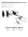
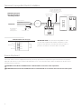
INSTRUCTION BOOK FOR
Tensioned Cosmopolitan Electrol
For Sizes Up To 10' x 10'
Important Safety Instructions
Pre-Installation
When using your video equipment, basic safety precautions
should always be followed, including the following:
1. Carefully unpack screen and remove outer wrapping
from case.
1.
2. Remove shipping brackets by removing the screws from
the slat bar and wooden board and use supplied 1/8" next
key to remove silver shipping brackets attached to slat.
Read and understand all instructions before using.
2. Position the cord so that it will not be tripped over, pulled, or
contact hot surfaces.
3. Always handle screen in horizontal position.
3. If an extension cord is necessary, a cord with a current rating
at least equal to that of the appliance should be used. Cords
rated for less amperage than the appliance may overheat.
4. To reduce the risk of electric shock, do not disassemble this
appliance. Contact an authorized service dealer when repair
work is required. Incorrect reassembly can cause electric
shock when the appliance is used subsequently.
5. The use of an accessory attachment not recommended by
the manufacturer may cause a risk of fire, electric shock, or
injury to persons.
Save These Instructions
Installation
There are three methods of mounting to include:
Flush against wall; Suspended from ceiling (use extension brackets); and recessed above ceiling.
Wall Mounted
Concealed (Allow Room For Access)
Ceiling
Mounted
Picture
Surface
Picture
Surface
Picture
Surface
Use No. 6
Brackets To
Hang Behind
Beam or
Valance
Picture
Surface
NOTE: Under no circumstances should unit be completely sealed in recessed installation. Allow access for service. Picture surface is centered
in case. Case extends 5-1/2" beyond surface on either end. Do not attach anything to screen slat rod or bottom fabric pocket.
1. Make sure screen is level. Use a carpenter‘s level and plumb level.
CAUTION! Do not cut wrapping paper or tape with knife or any
sharp tool. Remove by hand.
ATTENTION! Ne coupez pas le papier d'emballage ou le ruban
adhésif avec un couteau ou un outil tranchant. Retirez à la
main.
2. Install electrical hook-up that applies to your unit. Make sure to
review your Electrical Installation Checklists and Wiring Diagrams
(included) for either 120 Volt Switch, 220/240 Volt Switch, or Low
Voltage Control.
2
3. Test installation by running screen up and down a few times. Be
prepared to stop screen. Standard Duty Cycle:
1 MIN. ON / 3 MIN. OFF.
NOTE: Must be installed in accordance with the requirements of
the Local Building Codes, the Canadian Electrical Code (CEC),
CAN/CSA C22.1 and the National Electric Code (NEC), NFPA 70.
Tensioned Cosmopolitan® Electrol® Installation
Motor
End
4 5/8"
13/32"
Overall Length of Case
1 7/8"
3/4" Diameter
Hole For Wall
Installation
Between Hanger Eyes
3/8" Diameter For
Ceiling Mounting
5 7/8"
Enclosure Cover
7/8" Diameter Opening
For Electrical Settings
Picture
Surface
Slat
Overall Length of Slat
Wiring Enclosure Cover
120V Wiring Diagram
Up
Off
Down
Side View
Of Switch
And Box
Down
White Limit
Switch
Adjustment
Up Red
Common
White
Black
Rocker
Switch
Down Black
To Junction Box, Mounted In Screen Case,
In Which Internal Wiring Terminates In
White, Black and Red Leads
White
Red
Black With
Yellow
AC Common
AC Hot
120 V. 60 Hz. 2.5 Max. Amp
Operating Switch
And Plate Furnished
With Screen (SPDT
With Center Off)
This Switch Cannot Be Used With LVC.
In Multiple Control
Installations This
Switch Is Replaced By
The Low Voltage
Control, Operated
From Push Button
Stations.
NOTE: A single switch cannot be used to operate more
than one screen. Contact the factory for further
information.
240 VOLT WIRING DIAGRAM FOR STANDARD WALL SWITCH:
Da-Lite offers two styles of 240 volt wall switches for standard
operation. Please see wiring diagram included in wall switch box
included with screen.
3
120V Wiring Diagram with Optional Built-In Low Voltage Control
3-conductor 20-24 gauge wire can be used in place of the
supplied RJ-14 cable to connect the wall switch. Connect the BUS
terminals on the wall switch to the corresponding BUS terminals
on the splitter board.
IMPORTANT NOTE: The wall switch is REQUIRED to make any
limit switch adjustments, EVEN if a third party control system is
used. Therefore, it is advised to wire the switch or provide a
3-conductor connection that is accessible.
RJ-22
Jack
LED
RJ-22 Output
RJ-22
Jack
Up Limit
Tactile
Button
UP
Up
Down
Common
Bus
5V
RJ-22
Inputs
Dry Contacts
BUS
RJ-45 Receptacle
STO
P
RJ-45 Jack
5V
COM
BUS
DOW
N
Down
Limit
Tactile
Button
Front Of
Wall Switch
Data Cable
BUS
Back Of
Wall Switch
Power Wire
Green (Ground)
Black (Hot)
White (Common)
Ground–Must Be Connected
To Building Ground
Power Input 120VAC / 60Hz
RJ-14 Pin-Outs (Tab Is Facing Up)
RJ-22 Pin-Outs (Tab Is Facing Up)
+12V
White
Bus (RP Data)
Yellow
RQ Data
Green
RQ Data
Green
+5V
Ground
Red
Black
Supplied RJ-14 cable
4
Blue
Bus (RP Data)
+5V
Red
Ground
Black
RQ Clock
White
Standard RJ-22 can be used in place of RJ-14
RJ-45 Pin-Outs (Tab Is Facing Up)
Manual 2
+12V
Bus (RP Data)
RQ Data
+5V
Ground
RQ Clock
Manual 1
Brown
Blue
Yellow
Green
Red
Black
Orange
Purple
120V Wiring Diagram with Optional Built-In Video Projector Interface
CAUTION: The projector must be turned off before
connecting the trigger wires to the projector. Failure to do
so may damage the controller.
ATTENTION: Le projecteur doit être éteint avant de brancher
les fils de déclenchement à celui-ci. Tout manquement à
cette instruction pourrait endommager le contrôleur.
Use 2-conductor 20-24 gauge wire to extend the low voltage
connection from the projector’s 5 or 12-volt screen trigger output
to the length required to reach the VPI. When extending the low
voltage connection from the projector’s screen trigger output
polarity does not matter. The red and black wires from the VPI
are interchangeable.
Up
Limit
Tactile
Button
Up
Down
Common
Bus
5V
RJ-22
Inputs
RJ-22
Jack
STO
P
Down
Limit
Tactile
Button
5V
COM
BUS
DO
WN
Front Of
Wall Switch
3-conductor 20-24 gauge wire can be used in place of the
supplied RJ-14 cable to connect the wall switch. Connect the
BUS terminals on the wall switch to the corresponding BUS
terminals on the splitter board.
RJ-22 Jack
RJ-22 Output
LED
UP
IMPORTANT NOTE: The wall switch is REQUIRED to make any
limit switch adjustments, EVEN if a third party control system is
used. Therefore, it is advised to wire the switch or provide a
3-conductor connection that is accessible.
Dry Contacts
BUS
RJ-45 Receptacle
RJ-45 Jack
BUS
Data Cable
Back Of
Wall Switch
Power
Wire
Black
Red
VPI Trigger Module
5/12 Volt Screen
Trigger On Projector
Green (Ground)
Black (Hot)
White (Common)
Ground–Must Be Connected
To Building Ground
Power Input 120VAC / 60Hz
5
Tensioned Cosmopolitan® Electrol® Installation
Connect Supplied RJ9 Cable
to Splitter and Switch, or use
4 Cable Conductor to Connect
to Screw Terminals.
240V Wiring Diagram
With Optional Built-In
Low Voltage Control
Optional IR and RF
Remote Control
Low-Voltage Wall Switch
Blue (Common)
Brown (Hot)
240VAC 50Hz
Motor
RJ9
RJ9
Green
GND +5V
3-Position
Switch
RJ9
Stop
Down
Ground–Must be
Connected to
Building Ground
UP DN
Up
Ground to Case
UP
+5V
COM
DN
Green
Front
Back
Splitter
Dry Contacts
ILT RJ9 Pin-Outs (Tab Is Facing Up)
IR or Up
Ground Common
Black
Red
+5V
Green
DN or Data
White
IMPORTANT NOTE: The wall switch is REQUIRED to make
any limit switch adjustments, EVEN if a third party control
system is used. Therefore, it is advised to wire the switch or
provide a 4-conductor connection that is accessible.
Screen Adjustment
The screen surface travel is stopped automatically in the fully opened and closed positions by limit switches that are properly
adjusted at Da-Lite. The screen should not be adjusted for more or less drop. The fabric cables are adjusted for proper vertical
and lateral tension at Da-Lite.
CAUTION! Contact Da-Lite at 800-622-3737 or 574-267-8101 if screen motor needs adjustment.
ATTENTION! Contactez Da-Lite au 800-622-3737 ou au 574-267-8101 au cas le moteur de l'écran a besoin d'être ajusté.
6
Troubleshooting
Visit www.da-lite.com to find installation and troubleshooting
tutorials. You will also find a link to Live Chat for interactive
support and you can contact us by email at
Symptom
Screen will not operate.
Motor does not hum.
[email protected] or by phone at (800) 622-3737 or (574) 267-8101
with any troubleshooting questions.
Cause
Solution
Incorrect line voltage.
Verify 115-125V (or 220-240V). If insufficient voltage, rewire
incoming electric line.
Blown fuse.
Replace fuse.
Tripped circuit breaker.
Reset circuit breaker.
Check above. Tighten all loose wire connections.
Correct any improper connections.
“Down” Position
No power to operating switch or junction.
Check for power across black and white leads.
“Up” Position
Check for power across red and white leads.
Power at junction box.
Thermal overload tripped.
Let motor cool down for 15 minutes. Try again.
Broken wire in the “up” or ”down” position.
Check for continuity. Cut off old splice and reconnect.
Defective motor, limit switch or capacitor.
Replace motor assembly.
NOTE: Motor is a sealed assembly.
Temporary binding.
With power “off”, turn roller by hand to free binding.
Capacitor burned out.
Replace motor assembly.
Incorrect stopping position in
downward direction.
“Down” limit switch out of adjustment.
Contact Da-Lite at 800-622-3737 or 574-267-8101.
Incorrect stopping position in
upward direction.
“Up” limit switch out of adjustment.
Contact Da-Lite at 800-622-3737 or 574-267-8101.
Noise.
NOTE: Screen will operate
with a low pitched hum.
Gear noise.
Replace motor assembly.
Coasting.
Defective brake.
Replace motor assembly.
Roller displaced from
mounting bracket.
Pin end slipped out of nylon bearing.
Realign pin end bracket.
Motor hums.
7
LIMITED ONE YEAR WARRANTY ON DA-LITE PRESENTATION PRODUCTS
Milestone AV Technologies LLC warrants certain Da-Lite branded products to the original purchaser only, to be free from defects in
materials and workmanship for a period of one (1) year from the date of purchase by the original purchaser; provided they are properly
operated according to Da-Lite's instructions and are not damaged due to improper handling or treatment after shipment from the
factory.
This warranty does not apply to equipment showing evidence of misuse, abuse or accidental damage, or which has been tampered
with or repaired by a person other than authorized Da‑Lite personnel.
Da-Lite’s sole obligation under this warranty shall be to repair or to replace (at Da-Lite’s option) the defective part of the merchandise.
Returns for service should be made to your Da-Lite dealer. If it is necessary for the dealer to return the screen or part to Da-Lite,
transportation expenses to and from Da-Lite are payable by the purchaser and Da-Lite is not responsible for damage in shipment.
To protect yourself against damage or loss in transit, insure the product and prepay all transportation expenses.
TO THE MAXIMUM EXTENT PERMITTED BY APPLICABLE LAW, THIS WARRANTY IS IN LIEU OF ALL OTHER WARRANTIES, EXPRESS
OR IMPLIED, INCLUDING WARRANTIES AS TO FITNESS FOR USE AND MERCHANTABILITY. Any implied warranties of fitness for use,
or merchantability, that may be mandated by statute or rule of law are limited to the one (1) year warranty period. This warranty gives
you specific legal rights, and you may also have other rights, which vary from state-to-state. TO THE MAXIMUM EXTENT PERMITTED
BY APPLICABLE LAW, NO LIABILITY IS ASSUMED FOR EXPENSES OR DAMAGES RESULTING FROM INTERRUPTION IN OPERATION
OF EQUIPMENT, OR FOR INCIDENTAL, DIRECT, OR CONSEQUENTIAL DAMAGES OF ANY NATURE.
In the event that there is a defect in materials or workmanship of a Da-Lite product, you may contact our Sales Partners at PO Box 137,
Warsaw, IN 46581-0137, (574) 267-8101, (800) 622-3737.
IMPORTANT: THIS WARRANTY SHALL NOT BE VALID AND DA-LITE BRANDED PRODUCTS SHALL NOT BE BOUND BY THIS
WARRANTY IF THE PRODUCT IS NOT OPERATED IN ACCORDANCE WITH THE DA-LITE WRITTEN INSTRUCTIONS.
Keep your sales receipt to prove the date of purchase and your original ownership.
A Milestone AV Technologies Brand
3100 North Detroit Street
Warsaw, Indiana 46582
P: 574.267.8101 or 800.622.3737
F: 574.267.7804 or 877.325.4832
E: [email protected]
www.da-lite.com
DL–0264 (Rev. 2) 10.14
© 2014 Milestone AV Technologies LLC. Printed in U.S.A.
76063