1
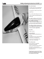
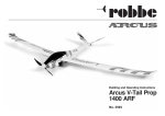
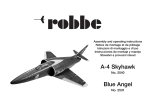
Building and Operating Instructions
Arcus V-Tail EDF
ARF
No. 2592
Building and Operating Instructions Arcus V-Tail EDF
Contents Page
Specification2
Essential accessories
2
Recommended accessories
2
Set contents
2
Radio control system
3
Colour scheme
3
Glued joints
3
Power system
3
Installing the tail panels
4, 5
Installing the wings
5
Installing the RC system components
6
Control surface travels
6
Centre of Gravity
6
Checking the working systems,
setting up the control surfaces
7
Test-flying, flying notes
7
Specification, 20 A speed controller
8
Programmable settings
8
The speed controller in use
8
Setting the throttle travel
8
Normal procedure when flying
8
Protective functions
8
Programming the speed controller
8
1. Starting programming mode
8
2. Selecting the programming point
8
3. Setting the programming point (value)
8
4. Quitting programming mode
8
Safety Information 8
Replacement Parts list
9
Guarantee9
Service Centre addresses
10
Conformity Declaration
10
2
Dear customer,
Congratulations on your choice of a factory-assembled model aircraft from the robbe
Modellsport range. Many thanks for placing your trust in us.
The model can be ready for the air when you have completed
just a few simple procedures.
Please read right through these instructions and the separate
information sheets before attempting to assemble and fly the
model, as this will make it much easier to complete the tasks
required.
Please study the illustrations and the brief instructions
to obtain a clear understanding of the individual stages of
construction. All parts must be trial-fitted “dry” (without glue)
before you reach for the glue. Assign the individual components to the various stages of assembly.
All directions, such as “right-hand”, are as seen from the tail
of the model, looking forward.
We constantly strive to update our products to reflect the latest developments. You can find details of technical improvements and revised documentation on the Internet by calling
up the appropriate product description at our website: www.
robbe.com.
The model
Not an everyday model; not just like all the others!
That's the Arcus V-tail EDF.
A compact model glider with the characteristic sound of an
EDF model jet. The model is equally suitable for the experienced pilot as well as the advanced beginner who is looking
for an EDF trainer, or simply fancies flying something rather
different for once.
The design and look of the Arcus V-Tail EDF are just as exclusive as its power system.
The model can also be fitted with an optional rudder servo.
Specification:
Wing loading approx.:
Length approx.:
Total surface area approx.:
All-up weight approx.:
Wingspan approx.: No. 2592
33.3 g/dm2
770 mm
15 dm2
500 g
1400 mm
RC functions:
Elevator, ailerons, throttle
Optional: Rudder
Essential accessories:
ROXXY® POWER ZY 3S 1300mAh 30C T6J-R2006GS 2.4 GHz FHSS T-socket pack of 10
Recommended accessories:
Charge lead, T-plug
POWER PEAK® A4 EQ-LCD 230V/12V Optional:
1x Servo 8.1 g 6913
F4100
8895
8881
8560
8975
Set contents:
• EPO foam fuselage, tail and wing with applied decals
• Finished canopy
• Control surface linkage hardware pack
• Assembled Ø 50 mm Fan unit with Brushless-Motor and
robbe E-COLINE controller
• 3 factory-installed robbe E-COLINE 8G servos
• Multi-lingual illustrated assembly instructions
Building and Operating Instructions Arcus V-Tail EDF
No. 2592
Note re. radio control system
For this model you require a radio control system with at least
4 channels. We particularly recommend 2.4 GHz systems.
The receiving system is powered by the speed controller’s
integral BEC system.
Before you check the model's working systems, set the control surfaces to neutral from the transmitter (transmitter sticks
and trims central).
Before flying the model always move the throttle stick to
the “motor stopped” position before switching the transmitter on. Only then connect the battery.
To switch off, first disconnect the flight pack from the
speed controller, and only then switch the transmitter off.
When installing or setting up the receiving system components, including the speed controller, be sure to read
and observe the instructions supplied with them.
Colour scheme
Painting is not necessary.
Carrying out glued joints
All parts must be trial-fitted “dry” (without glue) before you reach for the glue.
Please take great care to avoid excess adhesive running onto
the painted surfaces, as this will damage the finish.
The general rule is this: sand all painted joint surfaces
and remove all traces of dust before gluing.
Notes on the power system
A brushless outrunner motor is factory-installed.
The ducted fan unit is fully assembled.
The motor is connected to the speed controller, ready for use,
and the controller is correctly set up at the factory.
Prior to flying the model all you have to do is connect the LiPo
flight battery and the receiver.
Read right through the safety notes for the LiPo battery,
and the instructions supplied with the battery charger,
before using these items for the first time.
3
Building and Operating Instructions Arcus V-Tail EDF
1
Fig. 1
- The illustration shows both V-tail halves with the hard plastic joiner prior to assembly.
4
Fig. 4
- Finally fix the tailplane to the fuselage using the supplied
screws inserted from below and thread the pushrods into
the openings in the control horns. Dont screw the pushrods on yet!
4
2
Fig. 2
-Using Ropoxi 5-minute epoxy, glue both V-tail halves to the
hard plastic joiner.Allow the glue joint to harden.
5
Fig. 5
- Set the servo to centre (neutral) using the transmitter.
You can install a second optional servo for the rudder function if desired (see marking). If using this option, the V-tail
mixer must be used in your radio.
No. 2592
3
Fig. 3
- Place the V-tail unit into the opening in the fuselage. The
hard plastic joiner guide spigot must be inserted into the
guide tube in fuselage. Reinforce the tail to fuselage joint
with a 50 mm long strip of Tesa adhesive tape (see small
illustration on right)
6
Fig. 6
- Check the servo neutrals once more. The servo arm must be
at right angles to the servo.
Now you can permanently screw the pushrod to the control
horns.
Building and Operating Instructions Arcus V-Tail EDF
7
Fig. 7
- The illustration shows the assembled V-tail with linkages.
10
Fig. 10
- The illustration shows the completely installed ducted fan
unit with motor hatch. A magnetic catch secures the hatch
to the fuselage in operation.
8
Fig. 8
- Cut the aileron servo cover so that they fit into the cut-outs
in the foam servo mounts.
11
Fig. 11
- Insert the left hand wing and servo lead into the fuselage
opening. Slide the small connecting tubes through the right
hand fuselage side and into the left hand wing. Insert the
right hand wing onto the wing spar. Feed the servo lead
through the fuselage opening and slide the wing fully on
until it touches the fuselage.
No. 2592
9
Fig. 9
- Once the covers have been fitted, fix these to the wings
using strips of adhesive tape (see illustration).
- Repeat stages 8 and 9 on the other wing panel.
12
Fig. 12
- Insert the wing fixing plate and attach using the supplied
screw to the fuselage.
5
Building and Operating Instructions Arcus V-Tail EDF
13
14
Fig. 13
- Note: the ailerons should be connected to the receiver using
a Y-lead.
- Installing the receiver: connect the servos and the speed
controller to the receiver, referring to the RC system instructions for the correct channel assignment and connector
pin configuration. (the orange signal wire corresponds to the
white wire used for robbe-Futaba systems).
- Place the receiver in the fuselage and route the receiver
aerial(s).
16
15
Fig. 14
- Solder the T-socket to the battery. Ensure it has the same
polarity as that on the controller.
Insulate each soldered joint with a heat-shrink sleeve.
17
+15 mm
-10 mm
+10 mm
-10 mm
Fig. 16
- Aileron throw (a-b). +15 mm / -10mm
- Elevator throw +/- 10mm
6
No. 2592
mm
60
.
G
C.
Fig. 15
- Fix the receiver in the fuselage using Velcro tape.
Do not connect the battery at this point.
Fig. 17
- On this model the Centre of Gravity “C.G.” is located at
approximately the 60 mm point (measured from the wing
root leading edge).
- Place the battery in the model for balancing; do not connect it.
- Mark the Centre of Gravity on both sides of the fuselage,
as shown in the view of the underside.
- Support the model at the marked points and allow it to
hang freely. Ideally the model will now balance level, with
the nose inclined slightly down.
- Adjust the position of the flight battery if necessary.
- Mark the battery location in the fuselage, so that you can
be confident of replacing it in the same position after removing it.
- With the battery in the correct position, pack pieces of
scrap foam round it, so that it cannot shift in flight and alter
the model’s balance.
- The model is ready for flying once you have recharged the
battery.
Building and Operating Instructions Arcus V-Tail EDF
Checking the functions and setting up the control surfaces
- Charge the flight battery.
- Switch the transmitter on, and move the throttle stick to the
“motor off” end-point.
- Give the flight battery a full charge, apply Velcro (hookand-loop) tape to the pack, place it in the fuselage, and
connect it. Wait for the speed controller to emit a series of
beeps.
- Place the canopy on the fuselage.
- Check the channel assignment of the control surfaces, and
swap over the connectors at the receiver if necessary.
- Check the neutral position of the control surfaces. If necessary, loosen the clamping screws in the pushrod connectors, set the control surfaces to centre, then re-tighten the
screws.
- Check the direction of rotation of the servos.
- When you move the aileron stick to the right (a), the righthand aileron (a) should rise, the left-hand aileron (b) fall.
- Pull the elevator stick back towards you (c), and the rear
edge of both elevators should rise (c).
- If any of the control surface functions works the wrong way
round, correct it using your transmitter’s servo reverse
facility for that function.
-Check that all the linkages are firmly fixed, but freemoving. Check in particular that the nuts securing the
pushrod connectors are tight.
- The travels are measured at the inboard end of the control
surfaces.
- The stated control throws are just a guide for the first few
flights. The exact settings should be selected to suit the
individual pilot's flying style.
- The Expo settings should also be adjusted to suit the pilot's
preference.
No. 2592
Test-flying, flying notes
- Read the sections in the Safety Notes entitled “Routine
pre-flight checks” and “Flying the model” before attempting
to fly the model for the first time.
- For your initial test-flights please wait for a day with no
more than a gentle breeze.
- A good flying site consists of a large, flat, open grassy field,
devoid of trees, fences, high-tension overhead cables etc.
- Repeat the check of all the working systems.
- Ask an experienced modelling friend to hand-launch the
aircraft for you. He should be capable of giving the model
a reasonably strong, flat launch.
- The model must always be launched directly into any wind.
- With the motor running at full-throttle, give the aeroplane a
firm launch directly into any breeze, with the fuselage and
wings level.
- Keep the Arcus V-tail EDF flying straight and level at first;
don’t turn while it is still close to the ground.
- Adjust the control surface trims if necessary, so that the
model flies straight with a reasonable rate of climb “hands
off”.
- Check the model's response to control commands You
may need to increase or reduce the control surface travels
after the first landing.
- Check the glider's stalling speed at a safe height.
- Keep the model’s speed well above the stall for the landing
approach.
- If you needed to adjust the trims during the test-flight, correct the length of the appropriate pushrod once the model
is back on the ground, then return the transmitter trims to
centre so that full trim travel is available to both sides of
neutral for subsequent flights.
7
Building and Operating Instructions Arcus V-Tail EDF
Specification - 20 A speed controller:
Continuous current:
20 A
Peak current: 25 A, (max. 10 seconds)
BEC mode: Linear
BEC output: 5V / 2A
NiMH cell count:
5-9
LiPo cell count: 2-3
Dimensions (speed controller): 42 x 25 x 8 mm
Weight:
19 g
Caution: this controller is not protected against reversed polarity. Connecting a battery to the controller's
terminals with reversed polarity will instantly destroy the unit.
If you prefer to use a separate receiver battery instead of the BEC system, you must withdraw
the red wire from the receiver lead attached to the controller, and insulate the bare end to
avoid short-circuits.
VERY IMPORTANT: since different transmitters feature different throttle settings, we strongly advise you to use
the "Throttle range set-up function" to calibrate the throttle range. Please read the appropriate section in the
instructions.
Programmable settings:
1. Brake: on / off
2. Battery type: LiPo / NiMH
3. Low-voltage guard (Cut-Off mode): Soft Cut-Off (power reduction / cut-off (switches off immediately)
4. Low voltage cut-off voltage (Cut-Off threshold): low / medium / high
The cell count is detected automatically when Lithium batteries are used.
low (2.85 V) / medium (3.15 V) / high (3.3 V / 2.85 V / 3.15 V / 3.3 V.2)
5. Start mode: normal / soft / super-soft (300 ms / 1.5 s / 3 s)
6. Timing: low / medium / high (3.75° / 15° / 26.25°)
The normal setting is "low". A different setting can also be selected for higher motor speed.
The speed controller in use
Since the throttle travel is not the same for all radio control systems, it is essential to calibrate the throttle travel
before flying the model. If you are using a Futaba RC system, it is always necessary to set the throttle channel
(3) to "reverse".
Setting the throttle travel:
(the throttle travel should be re-adjusted if you change the radio control system)
1. Switch the transmitter on, and move the throttle stick to the full-throttle position.
2. Connect the battery to the speed controller and wait about two seconds.
3. You will hear a ”beep-beep” sound; this confirms the full-throttle setting.
4. Now move the throttle stick to the bottom position (towards you): you will hear several "beeps", indicating the
cell count.
5. You should hear a long “beep” to confirm the Idle end-point of the throttle stick.
Normal procedure when flying:
1. Move the throttle stick to the bottom position (towards you), and switch the transmitter on.
2. Connect the battery to the speed controller. A special sound similar to ♪“123” indicates that the power supply
is OK.
3. You should hear several “beeps” to indicate the cell-count of the Lithium battery.
4. You will hear a long "beep----" when the self-test is concluded.
5. To start the motor, move the throttle stick slowly forward until it reaches the end-point.
Protective functions:
1. Safety functions:
If the motor does not start running within two seconds of being switched on, the speed controller automatically switches itself off. The throttle stick must now be moved back to the "OFF" position.
8
No. 2592
Programming the speed controller:
(Note: please check that the throttle curve is set to 0%, the throttle stick is at the neutral position, and the
throttle travel is set to 100%).
1. Starting programming mode
2. Selecting the programming point
3. Setting the programming point (value):
4. Quitting programming mode
1. Starting programming mode
1) Switch the transmitter on, and move the throttle stick to "full-throttle". Connect the speed controller to the battery.
2) Wait two seconds: you should hear a “beep- beep-” sound.
3) Wait a further five seconds; you should hear a special ♪“56712” sound. The controller is now in programming mode.
2. Selecting the programming point:
When programming mode starts, the controller emits a sequence of eight different tones in a loop; the
sequence is described below. Move the throttle stick back to the neutral position within three seconds.
1. “beep” Brake (1 x brief beep)
2. “beep-beep-” Battery type
(2 x brief beep)
3. “beep-beep-beep-” Low voltage
(3 x brief beep)
4) “beep-beep-beep-beep-” Cut-off voltage (4 x brief beep)
5. “beep-----” Start mode (1 x long beep)
6. “beep-----beep-” Timing (1 x long, 1 x brief)
7. “beep-----beep-beep-” Reset to default (1 x long, 2 x brief)
8. “beep-----beep-----” Quit (2 x long beep)
3. Setting the programming point (value):
You will hear different sounds in a loop. You can set the sound value by moving the throttle stick to full-throttle,
after which you will hear a special ♪“1515” sound, which confirms and stores your chosen value. (You can return
to Step 2 by holding the throttle stick at the full-throttle position, and can then select a different point. Moving the
throttle stick back to the Neutral position within two seconds quits programming mode.)
Point
“beep” sound
“beep-beep-” sound
“beep-beep-beep” sound
(one brief beep)
(two brief beeps)
(three brief beeps)
Brake Off On
Battery type LiPo NiMH
–
Cut-off Soft cut Cut-off
–
Cut-off threshold low medium high
Start mode normal soft super-soft
Timing low medium high
4. Quitting programming mode
There are two methods of quitting programming mode:
1. In programming point 3: move the throttle stick back to the Neutral position within two seconds of hearing the special ♪“1515” sound.
2. In programming point 2: move the throttle stick back to the Neutral position within three seconds of
hearing the “beep-----beep-----” sound (e.g. Point No. 8).
Safety Notes
- Always keep to the power-on sequence: switch the transmitter on first, and then the receiver. Reverse
the sequence when switching off.
- Observe the limits stated in the Specification.
- Maintain correct polarity in all connections.
- Take great care to avoid short-circuits.
- Install and protect the speed controller in such a way that it cannot come into contact with grease, oil or water.
- Ensure that air circulation is adequate.
- Keep well clear of the rotational plane of the propeller when the motor is running - injury hazard.
Building and Operating Instructions Arcus V-Tail EDF
Replacement parts list Arcus V-Tail EDF
No.
Article description
Fuselage25920001
Wing set
25920002
V-tail set
25920003
Linkages and small parts 25920004
BL-Controller20A 25920005
Fan and shroud, 25920006
Decal sheet
25920007
BL-Motor
25920008
No. 2592
Guarantee
Naturally all our products are guaranteed for 24 months as
required by law. If you wish to make a justified claim under
guarantee, please contact your dealer in the first instance,
as he is responsible for the guarantee and for processing
guarantee claims. During the guarantee period we will rectify
any functional defects, production faults or material flaws at
no cost to you. We will not accept any further claims, e.g. for
consequential damage.
Goods must be sent to us carriage-paid; we will pay return
carriage costs. We wil l not accept any packages sent without
pre-paid postage.
We accept no liability for transport damage, nor for the loss
of your shipment. We recommend that you take out appropriate insurance.
Send your device to the approved Service Centre in your
country.
The following requirements must be fulfilled before we
can process your guarantee claim:
• You must include proof of purchase (till receipt) with the
returned product.
• You must have operated the product in accordance with
the operating instructions.
• You must have used recommended power sources and
genuine robbe accessories exclusively.
• There must be no damage present caused by moisture,
unauthorised intervention, polarity reversal, overloading
and mechanical stress.
• Please include a concise, accurate description of the fault
to help us locate the problem.
9
Building and Operating Instructions Arcus V-Tail EDF
Service Centre addresses
Country Andorra Denmark
Germany England France Greece Italy Netherlands / Belg. Norway Austria Sweden Switzerland Slovakian Rep.
Spain Czech Rep. Company Sorteney Nordic Hobby A/S
robbe-Service
robbe-Schlüter UK
S.A.V Messe
TAG Models Hellas
MC-Electronic
Jan van Mouwerik
Norwegian Modellers
robbe-Service
Minicars Hobby A.B.
robbe Futaba Service
Ivo Marhoun
robbe-Service
Ivo Marhoun
Street Santa Anna, 13
Bogensevej 13 Metzloser Str. 38
LE10-UB
6, Rue Usson du Poitou, BP 12
18,Vriullon Str.
Via del Progresso, 25
Slot de Houvelaan 30
Box 2140
Puchgasse 1
Bergsbrunnagatan 18
Hinterer Schürmattweg 25
Horova 9 Metzloser Str. 38
Horova 9
Town
AND-00130 Les escaldes- Princip. D‘Andorre
DK-8940 Randers SV
D-36355 Grebenhain
GB-LE10 3DS Leicestershire
F-57730 Folschviller
GR-14341 New Philadelfia/Athens
I-36010 Cavazzale di Monticello C.Otto (Vi)
NL-3155 Maasland
N-3103 Toensberg
A-1220 Wien
S-75323 Uppsala
CH-4203 Grellingen
CZ-35201 AS
D-36355 Grebenhain
CZ-35201 AS
Telephone
Fax
00376-862 865
00376-825 476
0045-86-43 61 00
0045-86-43 77 44
0049-6644-87-777
0049-6644-87-779
0044-1455-637151
0044-1455-635151
0033 3 87 94 62 58
0033-3-87 94 62 58
0030-2-102584380
0030-2-102533533
0039 0444 945992
0039 0444 945991
0031-10-59 13 594
0031-10-59 13 594
0047-333 78 000
0047-333 78 001
0043-1259-66-52
0043-1258-11-79
0046-186 06 571
0046-186 06 579
0041-61-741 23 22
0041-61 741 23 34
00420 351 120 162
0049-6644-87-777
0049-6644-87-779
00420 351 120 162
No. 2592
E-mail
[email protected]
[email protected]
[email protected]
[email protected]
[email protected]
[email protected]
[email protected]
[email protected]
[email protected]
[email protected]
[email protected]
[email protected]
[email protected]
[email protected]
[email protected]
robbe Modellsport GmbH & Co. KG hereby declares that this device conforms to the fundamental requirements and other relevant regulations of the corresponding EC Directive.
You can read the original Conformity Declaration on the Internet at www.robbe.com: click on the "Conformity Declaration" logo button which you will find next to the corresponding
device description.
This symbol means that you should dispose of electrical and electronic equipment separately from the household waste when it reaches the end of its useful life.
Take your unwanted equipment to your local council collection point or recycling centre. This requirement applies to member countries of the European Union as well as other nonEuropean countries with a separate waste collection system.
robbe Modellsport GmbH & Co.KG
Metzloserstraße 38 · D-36355 Grebenhain
Technical hotline: +49 (0)66 44 / 87-777 · [email protected]
Commercial register: Gießen Regional Court HRA 2722
Partner with personal liability:
robbe Modellsport Beteiligungs GmbH Gießen / HRB 5793 Managing Director: E. Dörr
Errors and technical modifications reserved. - Copyright robbe-Modellsport 2013
Duplication and copying of the text, in whole or in part, is only permitted with the prior written approval of robbe-Modellsport GmbH & Co. KG
10