1
USER’S MANUAL
Programming:
Robert Bocquier (v2.0)
Emilie de Fouchécour (v2.0)
Vincent Travaglini (v2.0)
Nicolas Bronnec
Sylvain Gubian
Xavier Oudin
Cedric Rossi
Graphics:
Morgan Perrier (v2.0)
Yannick Bonnefoy
Manual:
Robert Bocquier (v2.0)
Antoine Back (v2.0)
Jean-Michel Blanchet
Yuji Sano
Tom Healy
Mitsuru Sakaue
Xavier Oudin
Cedric Rossi
Kentaro Wakui
Sound Designers:
Jean-Michel Blanchet
Celmar Engel
Klaus Schulze
Ruff & Jam
Kevin Lamb from Neptunes
Chris Pitman
Silvère Letellier (v2.0)
Noritaka Ubukata
Darrell Diaz
Glen Darcy
Katsunori Ujiie
Pietro Caramelli
Very special thanks to:
Celmar Engel, Mark Vail, Alan R. Perlman, Wally Badarou, Chad from Neptunes
Thanks to:
John Leimseder, Matt Lupo, Ron Kuper, Mephistoff Ellys, Pietro Caramelli
and the numerous beta testers.
© ARTURIA SA – 1999-2014 – All rights reserved.
30, Chemin du Vieux Chêne
38240 Meylan
FRANCE
http://www.arturia.com
Information contained in this manual is subject to change without notice and does not represent a commitment
on the part of Arturia. The software described in this manual is provided under the terms of a license
agreement or non-disclosure agreement. The software license agreement specifies the terms and conditions for
its lawful use. No part of this manual may be produced or transmitted in any form or by any purpose other than
purchaser’s personal use, without the express written permission of ARTURIA S.A.
Other products, logos or company names quoted in this manual are trademarks or registered trademarks of
their respective owners.
November 2014 edition
2
Table of Contents
1 Introduction
1.1 The birth of ARP Instruments and the ARP2600
1.2 A better emulation thanks to TAE®
1.2.1 Aliasing-free oscillators
1.2.2 A better reproduction of analog oscillator waveforms
1.2.3 A better reproduction of analog filters
1.2.4 Ring modulator
2 ACTIVATION & FIRST START
2.1 Register & Activate
3 Quick start
3.1 Using presets
3.1.1 Now modify a preset
3.2 The 3 sections of the ARP2600 V
3.3 Overview of the Synthesizer
3.4 The sequencer
3.4.1 The ARP sequencer
3.4.2 The LFO
3.5 The effects
3.5.1 Chorus
3.5.2 Delay
3.6 Real-time controllers and MIDI assign
4 The interface
4.1 Using the presets
4.1.1 Choice of bank, sub-bank, preset
4.1.2 Creation of a bank, sub-bank, preset
4.1.3 Saving a user preset
4.1.4 Importation / Exportation of a preset bank
4.2 Use of controllers
4.2.1 Vertical linear potentiometers
4.2.2 Horizontal linear potentiometers
4.2.3 Knobs
4.2.4 The selectors:
4.2.5 Switches
4.2.6 Pitch Bend
4.3 Using cables
4.3.1 Audio and modulation connections
4.3.2 Modifying a connection
4.3.3 Setting the level of modulation
4.3.4 Separate the cables
4.3.5 Virtual keyboard
4.3.6 MIDI control
4.4 The sound map
4.4.1 The MAP main interface
4.4.2 The Sound Map overview
4.4.3 The LIST preset manager
4.4.4 The COMPASS morphing interface
5 The modules
5.1 Sound programming cabinet
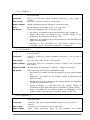
5.1.1 Description
5.1.2 The Oscillators (VCO)
5.1.3 The Filter (VCF)
5 5 6 6 7 8 8 9 9 10 10 11 13 13 16 16 19 20 20 21 22 23 23 23 24 24 25 26 26 26 26 27 27 27 27 27 29 29 30 30 31 34 35 37 39 40 43 43 43 44 47 3
5.1.4 The envelopes
5.1.5 Output amplifiers (Voltage Control Amplifier - VCA)
5.1.6 Noise Generator
5.1.7 Voltage processor (Mixer / inverter / lag generator)
5.1.8 Sample and Hold generator
5.1.9 The “electronic switch” module (Electronic switch)
5.1.10 Envelope follower
5.1.11 Ring modulator
5.1.12 “Tracking” generator
5.1.13 Reverberation
5.1.14 Chorus and delay effects
5.1.15 Control voltages (CV control)
5.2 Keyboard interface (Model 3620)
5.3 Low frequency oscillator (LFO)
5.4 The ARP sequencer
50 52 52 53 53 54 55 55 56 57 58 58 59 60 60 6 The basics of subtractive synthesis
63 6.1 The three main elements
6.1.1 The oscillator or VCO
6.1.2 The filter or VCF
6.1.3 The amplifier or VCA
6.2 Complementary modules
6.2.1 The keyboard
6.2.2 The envelope generator
6.2.3 The low frequency oscillator
6.2.4 The ring modulator
6.2.5 Sample and hold
63 63 67 69 70 70 71 72 73 73 7 A few elements of sound design
7.1 7.2 7.3 7.4 7.5 Simple patch without cabling
Polyphonic patch with cabling
Special effects patch with the help of the tracking generator
Patch using the sequencer to create a melody
Patch using the sequencer to create a modulation sequence
8 Modes of operation
8.1 Standalone
8.1.1 Launch the application
8.1.2 Configuration of the instrument
8.2 VST 2
8.3 VST 3
8.4 RTAS
8.5 AU
8.6 64 bit compatibility
8.7 Use in Cubase/Nuendo (VST)
8.7.1 Instrument use in VST mode
8.7.2 Rescan the plug-in directory in Cubase
8.7.3 Saving of presets
8.8 Using in Pro Tools (RTAS)
8.8.1 Opening of the plug-in
8.8.2 Saving the presets
8.8.3 Automation under Pro Tools
8.9 Using in Logic, Mac OS X (AU)
8.10 Using in Ableton Live (AU and VST)
ARP2600V END USER LICENSE AGREEMENT
4
75 75 78 81 84 86 88 88 88 88 89 89 89 89 89 90 90 91 91 91 91 92 92 92 93 95 1
1.1
INTRODUCTION
The birth of ARP Instruments and the ARP2600
Alan R. Pearlman, whose initials would form the name of ARP Instruments, became interested
in instruments for electronic music as early as 1948, when he was a student at the Worcester
Polytechnic Institute. This was a means for him to associate his two passions: electronic
music and the piano.
It was by commercializing the amplifier models for the NASA Gemini and Apollo programs
that he would start his career. Around 1968 he started seriously imagining the possibility of
building electronic instruments – after hearing a recording of “Switched-on Bach,” according
to legend.
In 1969, Alan R. Pearlman, David Friend and Lewis G. Pollock created ARP Instruments
(originally called Tonus Inc.). The company, based in Newton Highlands (Massachusetts,
USA), conceived electronic products, but also and above all else a large modular synthesizer,
the ARP 2500. The machine used a matrix which connected the different sections of the
synthesizer, instead of the traditional cables found in the Moog Modulars. The ARP 2500
found success in American universities.
The growth of ARP instruments was fast and in 1972 the ARP 2600, probably the most
legendary of the entire range, was unveiled. This semi-modular synthesizer, conceived with
an educational goal, was to become hugely successful after a shaky start. The ARP 2600 was
notably used by Stevie Wonder, Joe Zawinul (Weather Report), Tony Banks (Genesis), JeanMichel Jarre, Herbie Hancock... ARP was the market leader in synthesizers during the 70’s
with around 40% of the market share.
In ten years, three versions of the ARP 2600 were commercialized: The first version was
called “Blue meanie” because of its steely blue finish. The “blue meanie” was quickly replaced
by a second version, with a grey background finish and white silk screening (1972). This was
to be more popular. In 1978 ARP decided to change the graphic chart for all of its machines:
a black background color with orange silk screening was introduced. The ARP2600 benefited
from its third and last version.
The great rival of ARP was Moog Music. The competition between the two manufacturers can
easily be seen when we observe the machines: The ARP, for example, has linear
potentiometers, while the Moog has rotating pitch bend and modulation wheels.
A well known episode of this competition was the 24 dB/octave filter, the 4012, used by the
ARP. This was a replica of the famous Moog filter. In 1973, Moog threatened ARP with legal
action and the firm decided to change the circuits on its filter. The 4072 was born and took
the place of the 4012. This possessed a calibration error in the high frequencies – the
maximum cut-off frequency was less than 11 kHz instead of the 16 kHz promised in the
press. Luckily the repair for users was fast and not much of a burden. On the first ARP
2600’s, the 4012 filter was still used (this was the case for the “Blue meanie” and on the first
examples of the “grey and white”) while the models that followed offered the 4072.
The ARP synthesizers possess very stable oscillators, more reliable than the Moog
synthesizers (a fact admitted by Robert Moog himself). On the other hand, ARP for a long
time dipped the electronic circuits for filtering in resin to avoid industrial piracy... this made
for major problems when trying to perform a repair.
In 1972, ARP launched the Odyssey, which would be in direct competition with Moog Music
and their Minimoog released one year earlier. The same year, the Pro-Soloist, a preset
instrument, was also unveiled.
5
In 1976, ARP released a small 16 step sequencer in the form of 2 independent 8 step
sequences. This became famous and is still very sought after (it is emulated in the ARP2600
V.) The same year they presented the Omni, which would become one of ARPs biggest
successes. The instrument allowed the combination of two polyphonic violin sounds – a great
innovation for the company – and 2 monophonic bass sounds.
In 1976, ARP released a small 16-step sequencer in the form of two independent 8-step
sequences. This became famous and is still very sought after (it is emulated in the ARP2600
V.) The same year they presented the Omni, which would become one of ARPs biggest
successes. The instrument allowed the combination of two polyphonic violin sounds – a great
innovation for the company – and two monophonic bass sounds.
But in 1981, ARP was finally bought out by CBS. The following year, CBS with part of the ARP
development team would produce the Chroma, a programmable polyphonic synthesizer, and
in 1984 the Chroma Polaris, a simplified and MIDI-capable version of the Chroma.
1.2
A better emulation thanks to TAE®
TAE® - True Analog Emulation - is a new technology dedicated to the digital reproduction of
analog circuits used in vintage synthesizers.
When implemented in software code, TAE’s algorithms guarantee authentic emulation of
hardware specifications. This is why your ARP2600 V offers an unparalleled quality of sound.
In detail, TAE® combines four major advances in the domain of synthesis:
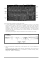
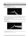
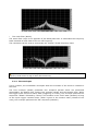
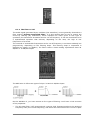
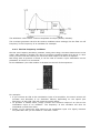
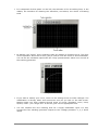
1.2.1 Aliasing-free oscillators
Standard digital synthesizers produce aliasing in high frequencies, and also when using Pulse
Width Modulation or FM.
TAE® allows the production of totally aliasing-free oscillators in all contexts (PWM, FM…), and
at no extra CPU cost.
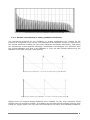
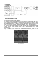
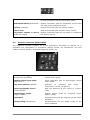
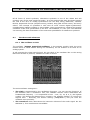
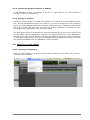
Aliasing
Linear frequency spectrum of an existing well-known software synthesizer
6
Linear frequency spectrum of the ARP2600 V oscillator made with TAE
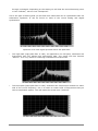
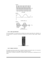
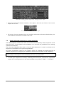
1.2.2 A better reproduction of analog oscillator waveforms
The waveforms produced by the oscillators in analog synthesizers are marked by the
presence of a capacitor in the circuits. The discharge of the capacitor results in a light bend in
the original waveform (notably for saw tooth, triangular and square waveforms). TAE allows
the reproduction of this capacitor discharge. Underneath is the analysis of a waveform from
the original ARP2600, and that of the ARP2600 V. They are both equally deformed by the
ARP2600 V low-pass and high—pass filtering.
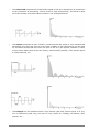
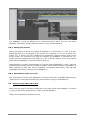
Temporal representation of a “saw tooth” waveform of the original ARP2600
Temporal representation of an ARP2600 V “saw tooth” waveform reproduced by TAE
What’s more, the original analog oscillators were unstable. In fact, their waveform varied
slightly from one period to another. If we add to this the fact that the starting point for each
period (in Trigger mode) can vary with the temperature and other environmental conditions,
7
we find one of the characteristics that contributed to the typical sound of vintage
synthesizers.
TAE reproduces the instability of oscillators, bringing a fatter and “bigger” sound.
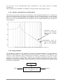
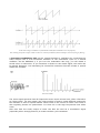
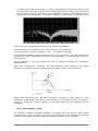
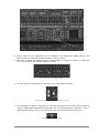
1.2.3 A better reproduction of analog filters
TAE allows more precise emulation of analog filters than standard digital filters. To obtain this
result, the TAE technology is based on the analysis of the analog circuits to be reproduced,
and converts them into algorithms that faithfully mimic the characteristics of the original
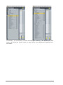
filters. The curve underneath shows the comparison of the original ARP2600 filter and that of
the ARP2600 V.
Response curve of
the 12 dB low-pass
filter of the original
ARP2600
Response curve of
the 12 dB low-pass
filter of the ARP2600
V
Response curve of the 12 dB low-pass filter of the original ARP2600 and the ARP2600 V
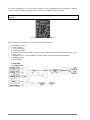
1.2.4 Ring modulator
The ARP2600 V includes a ring modulator, just like the original ARP2600. The ring modulator
allows the application of a waveform (a sinusoid) to another, in order to transform it. The
result is a more brilliant sound, distorted, and enriched in harmonics. As a result of this
increase in the number of harmonics, standard ring modulation algorithms create an audible
aliasing. To avoid this unwanted effect, TAE includes a module for the dynamic control of the
amplitude with aliasing correction, which removes every trace of aliasing in the signal coming
from the ring modulator.
Sine wave
form
Input
8
Amplitude control module
(VCA) with aliasing correction
Output
2
ACTIVATION & FIRST START
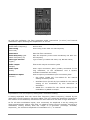
ARP 2600 V works on computers equipped with Windows 7 or 8 and Mac OS X 10.7 or
later. You can use the stand-alone version or use ARP 2600 V as an Audio Units, AAX,
VST2 or VST3 instrument.
2.1
Register & Activate
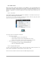
Once the ARP 2600 V has been installed, the next step is to register the software in order
to obtain the activation code that will enable you to use it.
The registration process will require you to enter the serial number and the unlock code
you received with the product.
In order to proceed, go to this web page and follow the instructions:
http://www.arturia.com/register
Note: If you don’t have an Arturia account yet, you will need to create one. The process
is quick, but it does require that you can access your e-mail address during the registration process.
Once you have acquired an Arturia account you will be able to register the product.
ARTURIA – ARP2600– USER’S MANUAL
9
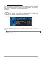
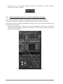
3
QUICK START
This chapter will help you to familiarize yourself with the general basics of using the
ARP2600 V. A summary of the different parts of the synthesizer will be presented to you
as we guide you through your first use of the program. You will find a detailed and
precise description of all settings and controllers in the following chapters.
Chapter 7, A few elements of sound design, is highly recommended for users who have
never worked with a subtractive synthesizer and who wish to become familiar with the
fundamentals in this domain.
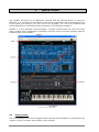
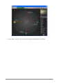
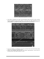
Overview of the ARP 2600V
3.1
Using presets
The use of presets is one of the biggest improvements of the ARP2600 V compared to the
original. In fact, the latter was unable to save sounds!
10
ARTURIA – ARP2600– USER’S MANUAL
In the ARP2600 V, a preset contains all of the parameter settings of the synthesizer,
including the synthesizer and different real-time controllers (eg: velocity, aftertouch,
pitch-bend) as well as the effects (delay, chorus) needed to reproduce a sound.
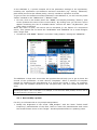
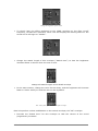
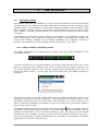
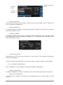
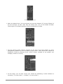
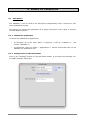
To get to know the different sounds contained in the ARP2600 V, we will use the preset
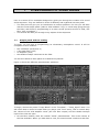
“Bass1” situated in the “JMBlanchet” / “Basses” bank.
! For this, click on the button above the “BANK” LCD display indicating “Factory” (this
screen presents the name of the current bank). By clicking here you will see a menu
appear containing the list of available banks. Choose the bank “JM_Blanchet” (the
bank name is checked) .
When this menu is open, sub menus can be accessed (in the fashion of a drop-down
menu). This system lets us access the “SUB BANK” and “PRESETS” for a sound designer
with a single click.
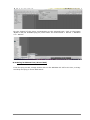
! Choose the “SUB BANK” “Basses” and select “JMB_Simple1” among the “PRESETS”.
Select the preset JMB_Simple1
The ARP2600 V ships with more than 400 presets that will help you to get to know the
sounds of the synthesizer. A bank named “Templates” offers a selection of template
presets for beginning the programming of a sound (the sound “1_Osc”, for example,
comes with: an oscillator directed to the low-pass filter, and then routed towards the
VCA).
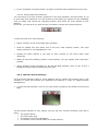
It is also possible to visualize the entirety of the presets corresponding to a type of sub bank by
selecting the option “All” in the bank. For example, to see all of the bass presets, click on “All” in
the bank selection and then on “Bass”.
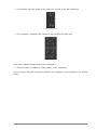
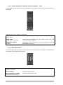
3.1.1 Now modify a preset
For this, we will start with a very simple manipulation.
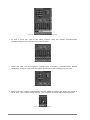
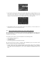
! Modify the brightness of the sound “JMB_Simple1” with the linear “Initial Cutoff
Frequency” potentiometer of the filter. Raise or lower the potentiometer and notice
the sound become more or less “bright”. Set this potentiometer to a pleasing value.
ARTURIA – ARP2600– USER’S MANUAL
11
Change the brightness of the sound
! In the same manner, you can change the range of oscillator 1 by setting the “Range”
selector to one of the values expressed in steps: LF = low frequencies, 32’ = -2
octaves, 16’ = -1 octave, 8’ = standard tuning, and 4’ = + 1 octave.
Setting the range of oscillator1
By performing these first settings, you have already modified the preset “JMB_Simple1”.
You will now see how to save the sound that you have created.
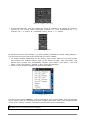
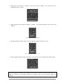
! To choose another destination for the sound, click on the “Save as” icon and choose
the location. For example select “new” in the choice of bank. Two new banks, sub
banks and a preset are immediately created. The names “new bank”, “new sub
bank…” and “new preset…” appear in their respective displays.
! Click on each of these displays to rename the 3 parts.
Saving a preset
To save a user preset (“Users”), click on the “Save” icon in the toolbar: The new settings
will be saved in the current preset without changing the name (but if the selected preset
is one of the “factory” presets, the factory setting will not be overwritten).
It is important to specify that changing the name of a preset does not create a new one! Only
the name of the current preset will be changed.
12
ARTURIA – ARP2600– USER’S MANUAL
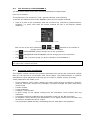
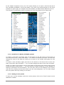
3.2
The 3 sections of the ARP2600 V
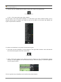
The ARP 2600V offers three main sections separated into flight cases:
From top to bottom:
The synthesizer, the sequencer / LFO / general settings, and keyboard
To access the different parts of the ARP2600 there are two simple methods:
! Click on a part of the synthesizer that des not have any controllers (potentiometers,
switches..) or jacks, then slide the mouse towards the top or the bottom without
releasing.
Slide the mouse towards the top or bottom
Click on one of the three shortcuts
,
and
situated on the toolbar to
quickly move from one section to another:
•
The
(SYNTHESIZER) section brings you to the synthesizer.
•
The
(SEQUENCER and KEYBOARD) section brings you to the sequencer.
•
The
(“ALL”) section brings you all the interface of the ARP2600 V
If you are in the “All” section, you can resize the window by clicking on the 2 arrows situated on
the right of the 3 sections shortcuts.
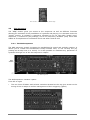
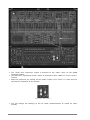
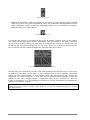
3.3
Overview of the Synthesizer
The “SYNTH” section contains 73 synthesis parameters as well as jack inputs and outputs
that you can connect to one another with virtual cables. The potentiometers or switches
associated to these parameters will help you to create an infinite variety of sounds.
These parameters are made up of:
•
•
•
•
•
•
•
•
Three oscillators (VCO) which release the audio signal through waveforms (triangle,
sinusoid, saw-tooth, square and rectangle) and which manage the pitch (frequency)
of the sound.
A noise module.
A ring modulator
A sample / hold module.
A mixer acting on the signals coming from the oscillators, noise module and ring
modulator.
A low-pass resonant 24 dB filter and multimode 12 dB (LP, HP, BP and notch)
An amplifier (VCA) allowing the amplification of the signal coming from the filter and
its direction towards the stereo output.
Two envelopes (ADSR and AR) modulating the low–pass filters and amplifier.
ARTURIA – ARP2600– USER’S MANUAL
13
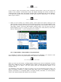
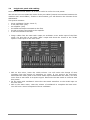
Synthesis parameters
Let’s look at quickly creating an evolving lead sound:
! To really understand the programming of the ARP2600 V, let’s use a very simple
sound. Select the preset “1_Osc” in the “Template / Temp_Synth” sub bank. The
structure of synthesis for this sound is relatively simple: the square waveform
oscillator1 is active and the signal is directed through the low-pass filter after an
intermediary mixer, and then on to the output amplifier. An ADSR envelope
modulates the filter cut-off frequency and a second envelope, AR, modulates the
volume of the amplifier.
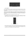
The following block diagram recaps the architecture of the creation of the sound:
The routing taken by the sound of preset “1_Osc”
! Start by reducing the low-pass filter cut-off frequency (LPF). This will dampen the
sound.
For this, set the linear “Initial Cutoff frequency” potentiometer (for fine tuning, use
the “Fine tune” potentiometer).
Notice that the filter cut-off frequency is modulated by an ADSR envelope (Attack,
Decay, hold - Sustain – and Release).
14
ARTURIA – ARP2600– USER’S MANUAL
Change the brightness of the sound
! To clearly hear the effect produced by the ADSR envelope on the filter cut-off
frequency, increase the resonance value. This will amplify the filtering effect on the
sound and it will begin to “whistle”.
Increase the resonance value
! Change the attack length of this envelope (“Attack time”) so that the brightness
increases faster or slower when the note is sent.
Change the attack length of the ADSR envelope
! In the same manner, change the value for the decay, and the brightness will increase
faster or slower while you hold the note on the keyboard.
The “Decay time” parameter on the filter envelope
Now let’s perform a short modification on the second envelope, the “AR” envelope.
! Increase the “Attack time” for this envelope so that the volume of the sound
progressively increases.
ARTURIA – ARP2600– USER’S MANUAL
15
Increase the “Attack time” of the AR envelope
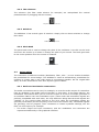
3.4
The sequencer
The “SEQ” section gives you access to the sequencer as well as different functions
allowing an extension of the possibilities of synthesis and playing. It is situated under the
“Synth” section. It contains a sequencer identical to the 16 step ARP (model 1601)
sequencer, a module for play settings, and a low frequency oscillator (LFO) which was
added as a complement to oscillator2 which was often used as LFO.
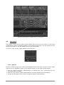
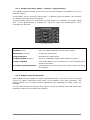
3.4.1 The ARP sequencer
The ARP sequencer greatly increases the possibilities for sound and melodic creation. It
allows you to create two simultaneous 8-step melodic lines, or one 16-step line (by
putting two 8-step lines in a series). It is also possible to modulate any parameter of
synthesis through one of the two sequencer outputs.
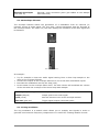
The ARP sequencer
The ARP sequencer contains 3 parts:
From left to right:
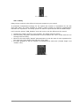
•
The two lines of faders and selector switches situated at the top give access to the
tuning of the 16 steps as well as management of their triggering (gates).
The two lines of faders and selector switches
16
ARTURIA – ARP2600– USER’S MANUAL
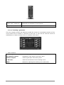
•
The oscillator sets the speed of the sequencer as well as the start and stop.
Set the oscillator speed
•
The “Quantizer” quantifies the values for the 16 steps by semi-tone.
The quantizer section
Let’s take a simple melodic sequence for example:
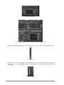
! Load the preset “Template”/ “Temp_SEQ”/ “1x16_sequencer”
You will notice that the connections between the sequencer and synthesizer are already
done:
ARTURIA – ARP2600– USER’S MANUAL
17
The connections between the sequencer and synthesizer
! The “Clock Out” sequencer output is directed to the “Gate” input on the ADSR
envelope module.
! The sequencer “Quantized A Out” output is directed to input “KBD CV” of the “VCO 1”
module.
! Start the sequencer by clicking on the “Start” button. This “turns” in a loop and you
will hear the repetition of the melody.
Click on the “Start” button
! You can change the settings of the 16 linear potentiometers to create an other
melody.
18
ARTURIA – ARP2600– USER’S MANUAL
Set the 16 linear potentiometers
3.4.2 The LFO
On the original ARP 2600, oscillator2 could be set to low frequency position (“LF” position
in the range) for use in LFO mode. Although practical, this solution prevented us from
using 3 oscillators simultaneously and a slow modulation on the filter cut-off frequency
for example.
Thanks to the LFO module situated on the “Keyboard control” module of the “All” mode,
you can keep the third oscillator as base sound and obtain an additional source of
modulation for one of the 13 available destinations. It is also possible to synchronize the
clock speed of the LFO to that of the MIDI sequencer by clicking on the “MIDI sync”
interrupter.
Apply two additional types of modulation to the preset “1_Osc”:
! For example: the LFO is “pre-cabled” to obtain a vibrato (simultaneous frequency
modulation) of the two oscillators. Simply raise the linear potentiometer “Vibrato
Depth”, situated on the LFO module, to create this effect.
Raise the “Vibrato Depth” potentiometer
! Another example would be to click on the LFO triangle output and direct the cable to
the “VCO2 sin” modulation input of the filter module. Raise the potentiometer above
it. Lower the cut-off frequency to hear the result more clearly. The brightness of the
sound will vary in a cyclic fashion, to the rhythm of the LFO.
ARTURIA – ARP2600– USER’S MANUAL
19
Modulate the filter frequency (“Cutoff Frequency”) with the LFO
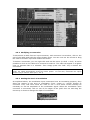
3.5
The effects
The effects section lets you add a Stereo Delay and Chorus to your sound on top of the
reverberation which is already present in the original instrument. The two effects can be
found in the place of the left speaker grid on the synthesizer.
To open it, click on the “open” button under this grid.
Open the effects grid
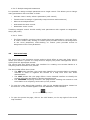
3.5.1 Chorus
Chorus is used to copy your sound, and slightly detune the copy, to give it more depth
and the Chorus “ON/OFF” button in the effects section, on the right of the toolbar.
! Set the Chorus “Dry/Wet” potentiometer to balance the “raw” sound and the one
returning from the effect.
! Next turn the Chorus “Rate” potentiometer to set the speed of the oscillations.
! Finally set the depth of the chorus using the “Depth” potentiometer.
20
ARTURIA – ARP2600– USER’S MANUAL
The chorus effect settings
3.5.2 Delay
Delay brings a stereo echo effect to bring more space to your sound.
It possesses independent settings for the speed and number of repetitions for the left
and right sides. It is also possible to create a large number of rhythmic combinations
between the repetitions. The delay speed can also be synchronized with the MIDI tempo.
Let’s keep the preset “JMB_Simple1” and see how to use the effects on this sound:
! Activate the “Delay” button on the toolbar. The effect becomes active.
! Set the Delay “Dry/Wet” potentiometer so as to balance the “raw” sound with the one
coming from the delay.
! Next turn the two Delay “Speed” potentiometers to set the rate of echo repetitions for
the right side (Time Right) and left side (Time Left).
! It is also possible to set the number of repetitions for each side (“Feedb. Right” and
“Feedb. Left”).
The Delay effect settings
ARTURIA – ARP2600– USER’S MANUAL
21
3.6
Real-time controllers and MIDI assign
Like its brilliant ancestor, the ARP2600 V is particularly adapted to real-time playing. One
of the main improvements when compared to the original is that we can assign any
potentiometer on the ARP2600 V to an external MIDI controller.
For example:
! Click on “MIDI Learn” button of the toolbar
! Click on the “Initial Cutoff frequency” potentiometer of the filter. A MIDI assign dialog
appears.
! Move the MIDI controller of your choice (the modulation wheel for example). The
ARP2600 V potentiometer will start to move at the same time.
! You can then record movements from your MIDI controller on your MIDI sequencer or
simply play live.
MIDI assign for “Cutoff frequency” potentiometer
To save the settings that we have seen in this chapter, click on the “Save” button in the
toolbar.
The MIDI assign settings are only saved when you quit the ARP2600 V application – be it
standalone or plug-in.
22
ARTURIA – ARP2600– USER’S MANUAL
4
4.1
THE INTERFACE
Using the presets
The presets memorize the ARP2600 V sounds. A preset contains all of the inter-module
connections and the different controller information necessary for the recreation of an
identical sound. In the ARP2600 V, presets are classed in “banks” and “sub-banks”. Each
bank contains a certain number of sub-banks, which determine a type of sound: subbank “basses”, sub-bank “sound effects”, etc. Each sub-bank contains a certain number
of presets.
The ARP2600 V comes with several “factory” sound banks. It is possible to create new
“user” sound banks, each containing an arbitrary number of sub-banks and presets. For
security, the “factory” settings are not directly modifiable. It is, however, possible to
modify a sound based on a factory preset and to record it to a “user” bank.
4.1.1 Choice of bank, sub-bank, preset
The banks, sub-banks and presets being currently used are always displayed in the
synthesizer toolbar.
Display of bank, sub-bank, and preset being used
To choose a preset in the current sub-bank, click on the button on the left of the current
preset, a drop-down menu appears with a list of presets from the same sub-bank. You
can choose another preset in the menu by selecting the corresponding line. Once the
preset has been chosen, you can play the new sound from your MIDI keyboard or
sequencer.
Choice of preset in the same sub-bank
To choose a preset in the same main bank, but in a different sub-bank, click on the
button on the left of the current sub-bank, a drop-down menu will appear with the list of
sub-banks contained in the same main bank. Each sub-bank in the menu allows you to
open a sub-menu containing its presets. A click on a preset lets you directly choose a
preset in the new sub-bank.
To choose a preset in another main bank, click on the button
next to the bank name. A
drop-down menu appears with the choice of the main banks that are available, and the
sub-lists corresponding to the sub-banks defined in each main bank and the presets
contained in each sub-bank. You can now freely choose a preset by clicking on its name.
Once a preset has been changed (modification of a controller or connection), an asterisk
appears next to its name in the tool bar.
ARTURIA – ARP2600– USER’S MANUAL
23
In the “BANK” dropdown menu, the “All” option allows you to open a sub-list with all of
the sub-banks available in all of the banks. This gives you access directly to all of the
presets of a given type, for example all of the basses, no matter which bank they are in.
This function is particularly useful to quickly see all of the presets of the same type.
The “All” option
4.1.2 Creation of a bank, sub-bank, preset
To create a new bank of sounds, click on the button on the left of the current bank. In
the drop-down menu, select “New bank...” to create a new bank of sounds. You can then
change the name of this bank by clicking on its name in the toolbar and typing the new
name.
To create a new sub-bank, again just click on the button on the left of the current subbank, and select “New sub bank...”. You can also change the name of the new sub-bank.
Finally, to create a new preset, click on the button on the left of the name of the current
preset and select “New preset...”. The new preset is created using the current ARP2600 V
settings (controllers and connections). You can then work on the settings of the sound,
and save it by clicking on the save button (see the next paragraph). You can also change
the new preset name by clicking on its name.
4.1.3 Saving a user preset
To save your current settings under the current preset, click on the “Save” button on the
ARP2600 V toolbar.
24
ARTURIA – ARP2600– USER’S MANUAL
“Save” button on the toolbar
If you want to save your preset under a different preset name, click on the “Save As”
button in the toolbar. A drop-down menu will appear allowing the choice of either an
existing preset (in this case, the preset contents will be replaced by the current setting),
or to save your preset as a new preset (in this case, click on “New Preset…” in the subbank of your choice).
“Save As” menu on the toolbar
! When you are working on a factory preset, which cannot be erased, clicking on the
“Save” button will not replace the current factory setting, but will automatically open
the “Save As” function to save the current setting as a user preset. Click on the
“New bank” option. The three LED displays indicate “New”: you can click on each of
these displays to give it a name or save your setting as a new preset (in this case,
click on “New preset...” in the sub-bank of your choice).
The “New preset...” option
4.1.4 Importation / Exportation of a preset bank
It is possible to import new preset banks created for the ARP2600 V. To import a new
bank of presets, click on the preset bank import button in the toolbar:
Preset bank import button on the toolbar
When you click on this button, a dialog appears allowing the choice of ARP2600 V preset
bank files (.AMB file type on PC, AMpB file type on Mac). Choose the file that you want to
import, and click on “Open”. The new preset bank will automatically appear in the
available banks.
The ARP2600 V also offers the option to export your own sound banks to save them, use
them on another machine, or share them with other users. It is possible to export a
preset, a sub-bank, or a complete bank. To export a bank, sub-bank, or current preset,
click on the export preset bank button on the toolbar:
ARTURIA – ARP2600– USER’S MANUAL
25
Current preset bank export button in the toolbar
Select the type of export that you wish to perform (bank, sub-bank or preset) from the
list and a window will appear prompting you to choose a destination folder and a name
for the file you are about to export.
4.2
Use of controllers
4.2.1 Vertical linear potentiometers
The ARP 2600V mainly uses linear potentiometers. To change the value of a vertical
potentiometer, click on it and move it vertically to the desired value.
Linear potentiometer
4.2.2 Horizontal linear potentiometers
To move these potentiometers, click on it and slide to the right or left to reach the
desired value.
Horizontal potentiometer
4.2.3 Knobs
You can find some knobs among the global settings, by exemple.
The default mode of control for knobs with the mouse is the linear mode: the knob can
be set only by vertically moving the mouse. It is possible to obtain a higher precision by
right clicking or Shift+Click on the concerned knob.
Knob
In circular mode, click on the knob and turn around it in order to change the value of the
controller. The circular mode gives high precision in the manipulation of controls: The
further the mouse goes from the knob, the higher the precision of the setting.
The linear mode is often more simple to use than rotation. But at the same time it cam be less
precise (the precision is limited by the number of vertical pixels on the screen from which the
mouse movements are evaluated). It is possible to attain a higher level of precision by rightclicking, or shift-click, on the potentiometer you want to control.
26
ARTURIA – ARP2600– USER’S MANUAL
4.2.4 The selectors:
The selectors (the filter mode selector for example) are manipulated like vertical
potentiometers by dragging with the mouse).
The filter “Modes” selector
4.2.5 Switches
The ARP2600 V has several types of switches. Simply click on these switches to change
their state.
MIDI sync on/off switch
4.2.6 Pitch Bend
The pitch bend knob is used to change the pitch of the oscillators. Just click on the knob
and move the mouse up or down to change the pitch of your sound. The knob goes back
to the center position when the mouse is released.
The pitch bend knob
4.3
Using cables
The connection of different modules (Oscillators, Filter, VCA...) to one another broadens
the possibilities for sound design. The ARP2600 V owes its extraordinary possibilities for
creation in a large part to the wide range of connections possible. On the original ARP
2600, all of the connections were done by two types of cables:
4.3.1 Audio and modulation connections
The audio connections can be used, for example, to route the audio output of a waveform
from an oscillator to the audio input of the filter or VCA mixer. In the same manner, the
modulation connections allow you to route the output of a LFO or envelope generator to
an oscillator PWM or the VCA modulation input. These audio and modulation signals are
perfectly compatible with each other, the only difference being that the audio signals are
“audible” of you connect them directly to the VCA, while the modulation signals are
generally not audible (as the frequency is too low for the human ear). Modulation signals
are generally used to program “slow” variations on certain synthesis settings, like the
filter cut-off frequency for example.
•
The audio output and input connectors, and the modulation out connectors are
represented differently in the graphical interface:
ARTURIA – ARP2600– USER’S MANUAL
27
Audio input connector
•
Additional modulation input connectors can be found on the tracking module located
under the grid of the right loud speaker. They are graphically distinguished from the
other connectors as they include an additional function: the modulation level setting,
described later on in this chapter:
Modulation input connector
To connect the output of a module to the input of another module, click on the output
and, while holding the mouse button depressed, drag the mouse to the input connector
of the second module. When you pass over a connector on which the current cable can
be placed, the connector will light up. In this case, when you release the mouse button,
the connection will be created between the selected input and output.
Creation of a new connection by drag and drop
Another way is to right click (on Mac: click while holding down the shift key) on the input
or output of a module. In this case, a menu appears with a list of possible connection
points for this input/output. It can happen that the input/output will already be
connected to certain modules; in this case the connection points already in use will
appear in this menu. Simply choose a connection point in the “Connect to” menu to
create a connection. It is also possible to delete the current connection by choosing the
“Remove connection” option.
Remark: Each modulation input can only receive one connection, but each output connector can be
connected to any number of inputs. This allows us to use one modulation signal on several
synthesis settings.
28
ARTURIA – ARP2600– USER’S MANUAL
Right click for input/output connection menu (or Shift + click)
4.3.2 Modifying a connection
To disconnect a cable from an input connector, and reconnect it to another, click on the
end of the cable and hold the mouse button down. You can now use the mouse to drag
the cable to another input and release the button.
To delete a connection, you can right click and use the menu (or Shift + click). It is also
possible to click on the cable to be removed to select it. The cable will appear in a lighter
color to indicate that it is selected. Then simply press the “DEL” key to delete the
connection.
Remark: You will have trouble selecting a cable if the “Move away cables” option is active! In this
mode, the cables automatically avoid the mouse pointer. To avoid this, deactivate this option
before trying to select a cable (see. 1.4.4.3)
4.3.3 Setting the level of modulation
As explained above, the modulation input connectors have an interesting property: they
allow the setting of the level of modulation (from –100% to +100%) directly at
connector level, and thus avoid the need to use a VCA which would normally be
necessary to set the amplitude of the modulation signal. When the modulation input
connector is connected, click on one of the edges of the jack’s hex nut and drag the
mouse up or down to change the depth of modulation:
Setting the quantity of modulation
By right clicking (or Shift + click) instead of the left click, you will obtain a more precise setting.
ARTURIA – ARP2600– USER’S MANUAL
29
If you click on the centre of the connector, you will select the cable end to change the
connection. To access the modulation setting, make sure you click on the nut. In the same way, if
you right click (or Shift + click) on the centre of the connector, you will reach the connection menu
instead of the precise modulation quantity setting.
4.3.4 Separate the cables
Visualizing the existing connections between different modules is very useful when
creating a patch on the ARP2600 V. At the same time, the cables can sometimes hide
access to some of the settings available on the modules. So as not to be hindered in your
manipulations, it can be useful to activate the “Move away cables” mode. In this mode,
the cables will automatically avoid the mouse pointer, leaving you with a clearer view to
checking or modifying potentiometer values. Don’t forget to deactivate this mode when
you want to select a cable with the mouse!
Deactivate the “separate the cables” mode
4.3.5 Virtual keyboard
The keyboard lets you listen to the synthesizer sounds without the need for an external
master MIDI keyboard, and without programming a melody in the sequencer. Just click
on a virtual key to hear the corresponding sound.
30
ARTURIA – ARP2600– USER’S MANUAL
4.3.6 MIDI control
Most of the knobs, sliders and switches on the ARP2600 V can be manipulated with
external MIDI controllers. Before anything else, make sure that the MIDI device that you
wish to use is correctly connected to the computer, and that the sequencer or the
ARP2600 V application is correctly configured to receive MIDI events coming from the
device.
4.3.6.1 Learn Menu
A new button and menu have been introduced in ARP2600 V. The button and menu provide access to MIDI assign functionalities.
The left part of the button activates the MIDI learn mode, while the right part (small
down arrow) opens the control management menu.
“Learn” Menu
“Learn Mode” Button
The “Learn” Menu is composed of 2 sections:
•
•
First section provides:
o
“New Config” creates a new controller set
o
“Save Config As” saves current configuration to a new one
o
“Delete Current Config” removes current configuration from list
The second section contains the list of existing configurations:
o
The checked one is the currently selected MIDI map
o
Click on a configuration to load it
4.3.6.2 Assigning MIDI Controls
In order to start assigning MIDI controls, click the “Midi Learn” button (left part). The
button remains highlighted to indicate that the “learn mode” is ON.
Click on a knob or button in the GUI to open the MIDI assignment popup.
ARTURIA – ARP2600– USER’S MANUAL
31
Plug-in parameter
name
Assigned
or not
Control
number
MIDI assignation popup
•
Learn assignment
The fastest and easiest way to assign a control is to move the fader, knob or button for it
to be recognized by ARP2600 V.
•
Manual assignment
It is also possible to change the assigned MIDI control number by clicking on Control#xx
and select a specific value.
•
Support for NRPN
In addition to MIDI Control Change messages, NRPN messages are now supported: either
send NRPN MIDI control messages to ARP2600 V, or check NRPN, then manually select
LSB# and MSB# numbers:
MIDI assignation popup, NRPN activated
•
Remove assignment
Assignments can be removed by clicking the “Clear” button. The message “Unassigned”
will then be displayed.
Continue selecting the parameters you want to map to create a complete configuration.
4.3.6.3 Manages Configurations
New in ARP2600 V: the possibility to maintain multiple configurations.
•
Default configuration
By default, ARP2600 V loads the configuration for Arturia Analog Experience keyboards.
•
Select one configuration
A configuration is loaded by clicking the corresponding entry in bottom part of “Learn
menu”.
32
ARTURIA – ARP2600– USER’S MANUAL
•
Create a new configuration
A new configuration can be created by clicking on the “Learn menu”, “New Config” entry.
This will open a popup: enter the name you want to call your configuration and click on
the “SAVE” button. A new entry for your configuration now exists in the list of available
configurations.
You may now fill in this initially empty configuration by performing the assignment operations described in the previous section.
•
Copy a configuration
It is possible to copy a configuration by loading it and then clicking on “Save Config As”.
A popup opens: enter the name of your configuration. A new entry for your configuration
now exists in the list of available configurations.
•
Remove a configuration
It is possible to remove a configuration by first loading it and then clicking on “Delete
Current Config”.
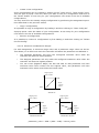
4.3.6.4 Minimum and Maximum Ranges
For each assignment, a minimum range value and a maximum range value can be set.
This allows you to limit how much the controller will affect the parameter on ARP2600 V.
•
The assigned parameter will have the configured minimum value when the
controller will be at its lowest position
•
The assigned parameter will only reach the configured maximum value when the
controller will be at its highest position
•
You can invert (Negative Slope) the Min and Max so that parameter will have
minimum value when control has the highest value, and parameter will have
maximum value when control has the lowest value
Output parameter values
MAX
Input
control
values
MIN
DEFAULT
Output parameter values
Output parameter values
MAX
Input
control
values
MIN
POSITIVE SLOPE
MIN
MAX
Input
control
values
NEGATIVE SLOPE
parameter_value = MIN + (MAX – MIN) * control_value
ARTURIA – ARP2600– USER’S MANUAL
33
4.3.6.5 Multiple Assigned Parameters
It is possible to assign multiple parameters to a single control. This allows you to change
many parameters with one fader or knob.
•
Activate “Learn” mode, select a parameter (GUI control)
•
Tweak control to assign it (optionally setup minimum and maximum)
•
Select a second parameter
•
And tweak the same control
•
Deactivate “Learn” mode
Tweaking assigned control should modify both parameters with regards to assignation
setup (Min, Max).
4.3.6.6 Tricks
•
4.4
The filter/amplifier envelope control points have two parameters: Level and Time.
If “Learn” mode is ON, clicking on control point provides access to the assignment
of the Level parameter, shift+clicking on control point provides access to
assignment of the Time parameter.
The sound map
The sound map is an innovative preset explorer which offers an easy and funky way to
locate and choose a preset on a map area to simplify the preset management and to
quickly find the appropriate sounds.
The sound map also offers brand new interface for creating new sounds thanks to a
morphing feature between four presets.
The Sound Map offers three views:
§ The MAP main interface: the sound map classifies the presets thanks to statistic
methods in order to organize the sounds on a map from their own audio
characteristics.
§ The LIST presets list: this page offers a more classical interface to classify the
presets using lists and filters to find the desired sound.
§ The COMPASS morphing interface: this page allows creating new sounds in real
time thanks to a morphing result with up to 4 presets.
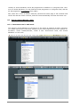
! To open the main Sound Map interface, click on the SOUND MAP button located on
the tool bar. A new window appears over the ARP2600 V main interface.
Open the main Sound Map interface
! To open the preset list page, click on the LIST button, on the top right of the sound
map interface
34
ARTURIA – ARP2600– USER’S MANUAL
Open the List interface
! To open the preset morphing page, click on the COMPASS button.
Open the Morphing interface
! To return back on the main sound map interface, click on the MAP button
Return back on the map interface
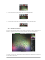
4.4.1 The MAP main interface
The sound map interface shows a map where are shared out all the presets of the
ARP2600 V organized for their types of sound and their own audio characteristics.
The Map interface
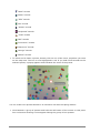
The types of presets are represented by different geometrical characters and colors for
an easy way to locate them:
ARTURIA – ARP2600– USER’S MANUAL
35
“Bass” sounds
“Brass” sounds
“EFX” sounds
“FM” sounds
“Guitar” sounds
“Keyboard” sounds
“Lead” sounds
“Pad” sounds
“Percussive” sounds
“Sequence” sounds
“Strings” sounds
“Others” sounds
! To select and to listen a preset, directly click on one of the icons, anywhere you want
on the map area. The icon is now highlighted in red. If you hold a few seconds on the
selected preset, a popup appears and indicates the name of the preset.
Select a preset
You can create new presets thanks to an exclusive real time morphing feature:
! Click between a group of presets and hold the left button of the mouse on this point.
Four red arrows drawing a cross appear linking the group of four presets.
36
ARTURIA – ARP2600– USER’S MANUAL
Morphing between a group of presets
! You can now drag your mouse between those presets. The green arrow shows you
the starting point of your motion.
! When you release the left mouse button, you can play the resulted sound and, if you
wish, you can save it on an ARP2600 V user bank.
By this way it is very easy to quickly get some new and exciting sounds without
programming anything on the synthesizer interface.
4.4.2 The Sound Map overview
On the top right of the Sound Map main interface, you can see an overview of this map.
You can use the map overview for navigating into the map and to zoom in or out inside
of the map area.
The map overview interface
! To navigate into the map, click inside of the red square and drag it on the map area
to view other sections of the Sound map.
! To zoom in the view on the sound map, click on the Zoom slider, under the overview
window, and drag it on the right to increase the size of the map.
! To zoom out the view on the sound map, click on the Zoom slider, and drag it on the
left to decrease the size of the map.
The zoom slider
ARTURIA – ARP2600– USER’S MANUAL
37
You can also use the “ZOOM +” or “ZOOM -” buttons, under the slider, to increase or decrease the map size
step by step (by factor 1).
! Click on the FIT ZOOM button allows resizing the map to its global size.
The FIT ZOOM button
4.4.2.1 The instrument type filter window
On the right of the map main interface, an instrument type filter window allows you to
choose which type of preset you want to see (or to hide) on the map. By default, all
types of presets are selected.
The instrument type filter
To select an individual or a group of instrument types:
! First click on the All button, on the bottom of the type filter window: this will hide all
the instrument types from the sound map.
The ALL button
! Then, select the type(s) you want to see by clicking on the corresponding square
box(es). A nock appears on the selected box(es) and the type(s) of presets appears
on the map interface.
Show pad presets
This is a good way to simplify and to refine the preset search.
38
ARTURIA – ARP2600– USER’S MANUAL
! If you click again on the All button, all types of presets will be displayed on the map.
4.4.2.2 Preset snap shot memories
You can select up to four presets, anywhere on the map interface, and save them on up
to four snap shot memories. You will be able to use those four presets on the COMPASS
view to create new sounds by morphing feature (see below for more details on this
feature).
Of course, you can save any kind of type of presets on these four snap memories.
Select a snap memory
To save a preset on a snap memory:
! Select a preset on the sound map main interface.
! Hold the [Shift] key and select one of the four snap memory button. The snap
memory button is now highlighted in red.
! Repeat the same actions if you wish to save presets on the three other snap
memories.
! When all memories already contain a saved preset, you can replace them with other
presets.
! Select another preset anywhere on the Sound Map interface, click on any of the 4
snapshot buttons while pressing the [Ctrl] key.
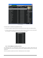
4.4.3 The LIST preset manager
The list preset manager offers a more classical way to explore the presets using a list
interface in which the presets are classified and filtered in order to simplify preset
management.
! To open the list interface, click on the LIST button located on the toolbar of the Sound
Map.
Click on the LIST button
The list preset interface is very simple, you can see four columns showing, from left to
right:
§ The preset names
§ The instrument type
§ The name of the sound designers
§ A reminder of the presets added to a snap memory
ARTURIA – ARP2600– USER’S MANUAL
39
Preset list interface
All those data are classified by alphabetical order.
! To select a preset, simply browse the list and click on the name of a desired preset.
! You can inverse the order (from A to Z or from Z to A) by clicking on the column title:
an ascendant or descendant arrow shows you the order type.
Inverse the order of the instrument types
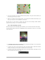
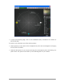
4.4.4 The COMPASS morphing interface
The Morphing page is an independent module allowing you to quickly create some new
sounds thanks to a real time morphing from the four selected presets saved on the snap
memories.
The four presets are placed on the four cardinal points of the compass.
40
ARTURIA – ARP2600– USER’S MANUAL
The Morphing interface
! To open the Morphing page, click on the COMPASS button, situated on the toolbar of
the Sound map.
To create a new morphed sound from those presets:
! Click anywhere on the centre of the compass area (four red arrows appear converging
to the group of presets)
! Hold the left button of your mouse and drag the convergence point until having the
good sound. The green arrow shows you the starting point of your motion.
ARTURIA – ARP2600– USER’S MANUAL
41
Create a new sound
!
42
If you wish, you can save it on a User bank of the ARP2600 V memory.
ARTURIA – ARP2600– USER’S MANUAL
5
THE MODULES
The ARP2600 V can be separated into 3 parts: from top to bottom, the first is a cabinet
dedicated to sound programming and effects, the second concerns the ARP sequencer
and the playing mode configuration interface with the keyboard and LFO, and finally the
third contains the keyboard.
5.1
Sound programming cabinet
5.1.1 Description
The programming section groups all modules which can be used to program sounds. It is
also in this screen where the different patches needed in the programming of a sound are
made.
It is sometimes necessary to connect a module in the programming section to a module
located in the sequencer section.
The sound programming section contains:
•
3 oscillators, which can also be used as modulation sources. (VCO)
•
1 multimode filter. (VCF)
•
1 amplifier (VCA)
•
2 envelopes dedicated to modulations
•
1 noise generator
•
1 ring modulator
•
1 envelope follower
•
1 sample and hold
•
2 mixers (on the filter and the VCA)
•
1 electronic switch
•
A tracking generator module
•
5 mixer / lag module
•
2 effects (chorus / delay)
ARTURIA – ARP2600– USER’S MANUAL
43
5.1.2 The Oscillators (VCO)
There are three oscillators in the ARP2600.
The oscillators permit the management of the base frequency and tone of the ARP 2600.
It also manages the impulse width of the waveforms. These changes can either be made
with linear potentiometers, or thanks to modulation inputs which can be connected to the
output of any module (envelope, low frequency oscillator - LFO -, modulation wheel…).
The oscillators can also be tuned and modulated separately with the potentiometers and
a range selector. These oscillators supply up to 4 waveforms that can be used
simultaneously.
These 3 oscillators, tuned separately and providing mixed waveforms, quickly give us
very rich sounds. The tone can also be easily modified with modulation inputs.
The 3 oscillators settings
44
ARTURIA – ARP2600– USER’S MANUAL
5.1.2.1 Oscillator 1
Range
General tuning of the oscillator by octaves. Up or down 4 octaves and
low frequencies
Frequency
Fine tuning
Tuning by semi-tone (Initial Oscillator Frequency). Up or down 2
octaves
Fine tune up or down by up to a semi-tone
Audio outputs
Output sawtooth & square waveform connection jacks
Sync
Synchronization of oscillator1 with 2, 3, or 2 and 3
FM Inputs
Frequency modulation input connection jacks
•
Key follow: pre-cabled for the manual setting of the (KYBD CV)
•
Sample and hold: pre-cabled for the manual setting of the
modulation by sample and hold (S/H out)
•
ADSR Env: pre-cabled for the manual setting of the modulation by
ADSR envelope ADSR
•
Oscillator 2 Sin: pre-cabled for the manual setting of the
modulation by sine waveform of oscillator 2 (VCO2 Sin)
5.1.2.2 Oscillator 2
Range
General tuning of the oscillator by octaves. Up or down 4 octaves and
low frequencies
Frequency
Tuning by semi-tone (Initial Oscillator Frequency). Up or down 2
octaves
Fine tuning
Fine tune up or down by up to a semi-tone
Audio outputs
Connection jacks for 4 waveform outputs: triangle, sine, saw-tooth
and square
Impulse width
Impulse width for “Sawtooth”, “Square”, “Triangle” waveforms
FM Inputs
Connection jack for frequency modulation inputs
•
Key follow: pre-cabled for manual setting of the key follow (KYBD
CV)
•
ADSR Env: pre-cabled for the manual setting of modulation by
ADSR envelope
•
Sample and hold: pre-cabled for the manual setting of modulation
by sample and hold (S/H out)
•
Square oscillator 1: pre-cabled for the manual setting of
modulation by the square waveform of oscillator1 (VCO1 square)
•
Noise: pre-cabled for the manual setting of modulation of the
impulse width of the square by the noise (PWM _ noise out)
5.1.2.3 Oscillator 3
Range
General tuning of the oscillator by octaves. Up or down 4 octaves and
low frequencies
Frequency
Fine tuning
Tuning by semi-tone (Initial Oscillator Frequency). Up or down 2
octaves
Fine tune on up or down by up to a semi-tone
Audio output
Audio
output
connection
ARTURIA – ARP2600– USER’S MANUAL
jacks
for
the
sawtooth
and
square
45
waveforms
Impulse width
Impulse width of the “Square” signal
FM Inputs
Frequency modulation input connection jacks:
•
Key follow (KYBD CV): pre-cabled for the manual setting of the
key follow
•
Noise (Noise): pre-cabled for the manual setting of the modulation
by the noise
•
ADSR Env: pre-cabled for the manual setting of the modulation by
ADSR envelope
•
Sine oscillator 2 (VCO1 sin): pre-cabled for the manual setting of
the modulation by the sine waveform of oscillator 2
•
Triangle oscillator2: pre-cabled for the manual setting of the
modulation of the impulse width of the square by the oscillator2
triangle (Pulse width modulation _ VCO2 Triangle)
! The general tuning of the 3 oscillators is done with the “VCO Initial frequency”
potentiometer by +- one octave per semi-tone.
! For fine tuning, set the Fine tune potentiometer to +/- one semi-tone.
! Depending on the position of the “Range” selector switch, the range is of +/- 4
octaves. It is also possible to set it to low frequency position (LF – for low frequency).
You will no longer hear any sound, but can now use it as LFO source of modulation.
! The impulse width applied to the “sawtooth”, “triangle” and “square” waveforms of
oscillators 2 and 3, can be modified with the “pulse width” potentiometer.
Oscillator 1 possesses two audio outputs for the sawtooth and square waveforms. These
can be used simultaneously. The second and third oscillators possess four outputs for the
sawtooth, sine, triangle and square.
The frequency modulation inputs (FM Control) and Pulse Width Modulation allow the
control of these parameters thanks to the outputs of other modules (an envelope, a LFO
for example) They are all pre-cabled to a defined module in advance by the developer of
the ARP 2600V2. This is to simplify the use of the synthesizer. For example: the
frequency of oscillator 1 can be modulated, from the left to the right, by the key follow,
the sample and hold, the ADSR envelope and the oscillator 2 sine. In low frequency
position (LF), the oscillators perform modulation using the lower CPU power compared to
the other positions.
! To set the modulation rate, use the linear potentiometer situated above the
corresponding jack.
! You can also connect another source of modulation to each input. This considerably
widens the possibilities for sound creation.
For a conventional key follow setting (in relation to the scale) place the potentiometer completely
to the top.
Here are graphical representations of the different waveforms used by ARP 2600V
oscillators:
46
ARTURIA – ARP2600– USER’S MANUAL
Sawtooth
Square
Triangle
Sine
5.1.3 The Filter (VCF)
The ARP2600 V possesses a multimode filter module (the original had only one resonant
low pass mode). It is possible to choose a filter type among the five offered: a low pass
24 dB (identical to that found on the ARP2600), a low pass, a high pass, a band-pass and
a notch 12 dB of the same kind as the one found on the ARP 2500 modulars. The change
of type is done by setting the selector situated on the right of the filter module.
ARTURIA – ARP2600– USER’S MANUAL
47
The filter settings
As with the oscillators, the filter possesses audio connections (a mixer) and internal
modulation inputs allowing the simplification of its use.
Frequency
(Initial Filter Frequency)
Sets the filter cut-off frequency, tuned between 10 Hz
and 10 KHz
Fine tuning
(Fine tune)
Fine tuning of the filter cut-off frequency
Resonance
Sets the filter resonance
Notch frequency / fc
(Notch Frequency/ fc)
Sets the frequency of the notch divided by the filter cutoff frequency
Filter type selector
(Types)
Type of filter (LP 2600 and 2500, HP, BP and notch)
Audio output
(Output)
Filter audio output connection jacks
Audio input
(Audio)
Filter input connection jacks (initially connected to the
ring modulator, to the oscillators1 and 2 square,
oscillator3 sawtooth and noise)
Modulation inputs
(Control)
Filter frequency modulation input connection jacks.
•
Key follow (KYBD CV): Pre-cabled for the manual
setting of the key follow
•
Oscillator3 sine (VCO3 Sin):pre-cabled for the manual
setting of the modulation by sine waveform of
oscillator2
•
ADSR Env: re-cabled for the manual setting of the
modulation by ADSR envelope.
It possesses a cut-off frequency setting and a resonance setting.
A setting separated from the notch filter frequency (Notch frequency) divided by the
initial filter cut-off frequency has been added. This very particular parameter (present on
the module of the ARP2500) transforms the notch filter to a low shell or high shell filter.
As for all other modulation inputs, once connected, its amplitude is set by raising the
linear potentiometer. With a right click, we obtain a higher level of precision. Receiving a
modulation coming directly from the output of a generator (envelope, oscillator,
sequencer), the maximum amplitude of modulation of +/- 9 octaves.
48
ARTURIA – ARP2600– USER’S MANUAL
Only the cut-off frequency can be dynamically modulated by one of the 3 modulation
inputs.
For a conventional key follow setting (in relation to the scale) place the potentiometer completely
to the top.
5.1.3.1 The filter types:
• The low pass 24dB / oct Low pass (LP 24)
The low pass 24dB filter is typical of the ARP2600. It eliminates the frequencies situated
below the pivotal frequency (the cut-off frequency).
The low pass filter
The four other filtering modes didn’t exist on the original ARP2600 but existed on the
ARP2500 modular systems. They all use a filtering slope at 12 dB/ octave. These modes
were added to increase the possibilities for sound creation on the ARP 2600 V 2.5.
• The low pass 12dB / octave (LP 12)
The low pass 12 dB filter is works in the same manner as the 24 dB/ oct. on the the
ARP2600. It will just give you a slightly different result due to the fact that its filtering
slope is not as fast.
• The high pass (HP 12)
The high pass filter is the opposite of the low pass filter. It eliminates the frequencies
above the cut-off frequency.
The high pass filter
• The band pass filter (BP 12)
The band pass filter is a combination of the low pass and high pass: It eliminates the
frequencies on each side of the cut-off frequency.
ARTURIA – ARP2600– USER’S MANUAL
49
The band pass filter
• The notch filter (Notch)
The notch filter coupe is the opposite of the band pass filter. It eliminates the frequency
band situated on both sides of the cut-off frequency.
The resonance can be used to accentuate the “hollow” of this frequency band.
The notch filter
if you raise the resonance too high, the result of the filtering will no longer be heard as the
frequency band will be too big to allow efficient filtering.
5.1.4 The envelopes
Two in number, the modulation envelopes allow the evolution of the sound in relation to
the time.
The first envelope (ADSR) possesses four temporal periods which are performed
sequentially: the Attack time, Decay time, Sustain voltage and the Release time. When
the trigger input moves to active state (triggering of a note), the envelope performs the
sequences “Attack” followed by “Decay” and remains in the “hold” state (Sustain) as long
as the input trigger remains active. When it goes to the inactive state (release of the
note), the envelope performs the “fall” sequence (Release).
50
ARTURIA – ARP2600– USER’S MANUAL
ADSR and AR envelopes settings
5.1.4.1 ADSR
Attack
(Attack time)
Sets the attack time
Decay
(Decay time)
Sets the decay time
Hold
(Sustain Voltage)
Sets the level of the hold
Release
(Release time)
Sets the release time
Output
(Output)
Envelope output signal
5.1.4.2 AR
Attack (Attack time)
Sets the attack time
Release (Release time)
Sets the release time
5.1.4.3 Trigger modes
Trigg input
(S/H gate)
“Gate”
(Gate)
output
Input connection for an external trigger signal (pre-cabled to
the Sample and Hold clock)
type
Output connection for a “gate” type signal: for every note
played on the keyboard, the signal remains active as long as
the note is held down.
“Trigger” output type
(trig)
Output connection for a “trigger” type signal: each note played
by the keyboard presents a sustain time reduced to the
minimum.
Switch
Sample
clock”
(S/H gate): Selection of the choice of envelope trigger - AR and
ADSR – by the keyboard or Sample and Hold clock. This
function reactivates the envelopes at every clock cycle.
“trigger
by
and
Hold
ARTURIA – ARP2600– USER’S MANUAL
51
5.1.5 Output amplifiers (Voltage Control Amplifier - VCA)
The amplifier is the last step in the conception of a preset. It sets the general volume of
the sound.
The VCA settings
This module is very simple; it contains:
Gain
(Initial Gain)
Sets the general synthesizer volume
Audio input
(Audio VCF / ring mod)
Audio input connection jack (pre-cabled to the filter and
ring mod audio outputs).
Modulation inputs
(Control)
Modulation input connection jacks (pre-cabled on the AR
and ADSR envelopes).
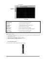
5.1.6 Noise Generator
The noise generator generates white noise or colored noise. It possesses a low pass filter
to dampen high pitched frequencies.
The noise generator
Low pass frequency
(White / Low Freq)
Sets the cut-off frequency of the low pass filter.
Noise volume
Sets the noise volume.
Noise generator output
(Noise generator output)
Noise out connection jack.
52
ARTURIA – ARP2600– USER’S MANUAL
5.1.7 Voltage processor (Mixer / inverter / lag generator)
The voltage processor allows you to mix up to 8 inputs (audio or modulation) to one (or
several) outputs.
It also allows you to invert the input signal – a positive-going modulation (an envelope
for example) will thus become negative.
A lag generator allows you to smooth an input signal. For example, the square signal
from a LFO approximates a triangle the more we raise the potentiometer value,
increasing the lag time.
The voltage processor
8 signal inputs (input)
Audio or modulation signal input connection jacks.
4 balance (mix)
Sets the balance between the two input signals
4 inverters (inverter)
Inverts the input signal
4 lag generators
Smoothes the input signal
4 signal outputs (output)
Audio or modulation signal output connection jacks
4 “Mix” switches
This switch allows you to merge one or several inputs pairs
into the one above.
4 “Volume” potentiometers
Potentiometer to set the volume of 2 input signals (A and B
for example)
5.1.8 Sample and Hold generator
This module lets you sample the signal connected as input. The source can be external
(source of trigger connected to the input) or pre-cabled to the noise generator. This
module allows you to create random modulations by sampling the noise signal, for
example.
You can also connect an external clock source to pilot the sample and hold speed (the
waveform output of an oscillator for example).
ARTURIA – ARP2600– USER’S MANUAL
53
The sample and hold settings
Level (Level)
Sets the Sample & Hold modulation level.
Rate (Rate)
Sets the Sample & Hold clock speed.
External Input
(“Noise gen”)
Audio or modulation external signal input connection
jack. (pre-cabled to the noise module)
Sample and Hold output
Sample and Hold output connection jack
Internal clock output
(Int Clock out)
Sample and Hold internal clock output connection jack
External clock input
(Ext Clock in)
External clock input connection jack
MIDI Synchronization
(MIDI sync)
Selector switch for the synchronization of the clock to a
MIDI sequencer.
5.1.9 The “electronic switch” module (Electronic switch)
The “Electronic switch” module allows you to alternate the two sources connected to
inputs A and B depending on the speed of the clock connected (pre-cabled to the Sample
and Hold clock) to create a composite source of modulation.
The electronic switch
An example:
! Connect the output of the square waveform of oscillator 1 to input A and the sine
output of oscillator 2 to input B.
! Place these two oscillators to low frequency position (LF) so as to slow the oscillation
speed. Set the frequency potentiometers for the two oscillators to 0.3 Hz.
! Connect output C of the interrupter to one of the filter modulation inputs.
! Set the Sample and Hold clock speed potentiometer towards the bottom to clearly
hear the alternation between the two modulations.
Inputs (A / B)
54
Audio or modulation signal input connection jacks.
ARTURIA – ARP2600– USER’S MANUAL
Selector switch (C)
Selector switch C connection jacks between signals A and B
External clock input
(Ext clock In)
External; clock connection jacks (pre-cabled to the Sample
and Hold clock)
5.1.10 Envelope follower
The envelope follower allows the generation of a modulation from an external (or
internal) source of audio signal. The (Pre amp.) volume parameter sets the fineness of
the envelope follow. The lower it is, the more closely the variations of the input signal will
be followed.
The preamplifier
The envelope follower
An example:
! Try for example to insert an audio signal coming from a drum loop sample to the
input of the envelope follower.
! Connect the output of the envelope follower to one of the filter modulation inputs.
! Increase the modulation rate for the amp (VCA).
! Do the same for the envelope follow level. The VCA volume will modulate the volume
of the VCA with the envelope of the drum loop audio sample.
Audio input (Pre-Amp)
Envelope follower audio input connection jack
Output (Output)
Output jack fo the audio signal
Level (Level)
Sets the amount level of the envelope follower
Gate out (gate out)
Trigger signal output connection jacks
5.1.11 Ring modulator
The ring modulator is a module which allows you to multiply two signals in order to
generate non-harmonic frequency components. It is useful for creating metallic sounds.
ARTURIA – ARP2600– USER’S MANUAL
55
The ring modulator
2 Audio inputs
(VCO1 Saw / VCO2 Sin)
Audio input connection jacks (pre-cabled to the oscillator1
sawtooth and oscillator 2 sine outputs).
Output (Output)
Ring modulator output connection jacks
5.1.12 “Tracking” generator
This very original module was added to modify the course of a modulation thanks to four
curves which can be edited in real-time by the user. It can also be used as source of
modulation to create envelope forms or complex LFO waves.
The tracking generator’s main interface
• Main interface:
4 audio inputs
Audio input signal connection jacks.
4 modulation inputs
Modulation input signal connection jacks
4 audio outputs
Audio signal input connection jacks.
4 “Smooth”
Sets the smoothness of the tracking curve.
4 Edit
Button for opening the tracking curve edit mode.
•
56
Edit interface
ARTURIA – ARP2600– USER’S MANUAL
Curve editing screen
Screen for real-time curve editing.
Drawing tool
Tool for drawing a freehand curve.
Line tool
Tool for drawing a straight line.
Curve tool
Tool for drawing an exponential curve.
Sine tool
Tool for drawing a sinusoid.
Square tool
Tool for drawing a square signal.
Noise tool
Tool for adding noise to an existing signal.
Eraser tool
Tool for erasing an existing signal.
Undo / Redo
To undo or redo a drawn signal.
A few tips for using it:
! To create an exponential curve: Firstly click on the editing screen to place the starting
curve for the curve.
! Drag (without releasing) to draw the curve.
! Click and drag up or down to set the amplitude.
! Click once again to validate this curve.
5.1.13 Reverberation
This module lets us add reverberation to the sound.
The reverb module
ARTURIA – ARP2600– USER’S MANUAL
57
Right effect level (Level)
Sets the output level for the right reverberation
Left effect level (Level)
Sets the output level for the left reverberation
Right output (Output R)
Right output connection
reverberation)
Left output (Output L)
Left output connection
reverberation)
Dry input right (Dry input right)
Dry right input connection jack
Dry input left (Dry input Left)
Dry left input connection jack
jack
jack
(with
or
without
(with
or
without
5.1.14 Chorus and delay effects
Chorus has three potentiometers, “Rate” “Depth” and “Dry/Wet” which allow us to
respectively set the speed, the depth and the relation between the original and modified
signals.
The chorus effect
Delay has two potentiometers, “Time Left” and “Time Right”, respectively for setting the
time for the left channel, and the right channel. The two potentiometers, “FeedB Left”
and “FeedB Right” respectively set the channel return gain for left and right channels.
Finally the “Dry/Wet” potentiometer sets the ratio between the original and modified
signals.
The delay effect
The “Midi Sync” selector switch allows us to synchronize the return time for the delay to
the tempo of the host application.
5.1.15 Control voltages (CV control)
These modulation outputs allow us to control the synthesizer parameters with the realtime controllers of your MIDI keyboard.
58
ARTURIA – ARP2600– USER’S MANUAL
The CV controls
Pitch bend wheel (Pitch bend)
Output connection jack for the control of modulation
of three oscillators with the pitch bend wheel.
Modulation wheel (Mod Wheel)
Output connection jack for modulation control with
the help of the modulation wheel.
Velocity (Velocity)
Output connection jack for velocity control.
After Touch
Output connection jack for After Touch control.
Key follow outputs x1 and x4
(KYBD CV output)
Output connection jacks for key follow x1 (tempered
key follow) and x4
5.2
Keyboard interface (Model 3620)
The keyboard interface contains all of the parameters necessary for playing on a
keyboard: the monophonic or polyphonic playing modes, the portamento, the LFO
(mainly used for vibrato), keyboard triggering modes, etc...
The keyboard interface
Portamento trigger input
(portamento footswitch)
pedal
Output connection jack for portamento trigger
control with a pedal.
Sustain trigger input pedal
(KBd Latch)
Input connection jack for Hold trigger control
with a pedal.
Play mode selector (Modes)
Selection
of
keyboard
play
monophonic, unison, polyphonic.
Detune polyphonic voices
(Unison detune)
Sets the detuning of the voices in “unison”
mode.
Select trigger modes
(Trigger modes)
Selects trigger
legato / retrig
Pitch Bend
Simultaneously sets the frequency of the three
oscillators.
Global tuning (Global tune)
Simultaneously set the global tuning of the
three oscillators
ARTURIA – ARP2600– USER’S MANUAL
mode
for
mode
keyboard
-
notes:
59
5.3
Low frequency oscillator (LFO)
The use or a low frequency oscillator as source of modulation is quite common. It allows
us to make the tone of a sound evolve gently or to create a vibrato or tremolo effect.
Even though three oscillators can be used at very low frequencies, there is a specific
module for this, allowing you to dedicate the oscillators to generation in the audible
domain.
The LFO
Low
frequency
speed (LFO speed)
oscillator
Sets the clock speed for the low frequency oscillator.
Low
frequency
delay (LFO delay)
oscillator
Sets the delay of the low frequency oscillator action.
Vibrato depth (vibrato depth)
Sets the depth of the vibrato.
MIDI synchronization
(MIDI sync)
The “Midi Sync” selector switch lets you synchronize
the low frequency oscillator clock with the MIDI tempo.
Triangle output (LFO triangle)
Audio output of the LFO triangle waveform.
Square output (LFO Square)
Audio output of the LFO square waveform.
Sawtooth output (LFO Saw)
Audio output of the LFO sawtooth waveform.
Sine output (LFO Sine)
Audio output of the LFO sinusoid waveform
External vibrato input
(LFO External Vibrato in)
Audio input for external LFO source.
5.4
The ARP sequencer
This module was born of the original ARP sequencer model 1601 (18). It was one of the
most widely used sequencers in the 70’s and early 80’s.
With this module, you will create melodic sequences or step by step variations applied to
synthesizer parameters (a sequence line applied to the opening of the frequency of a
filter can be very effective, for example).
60
ARTURIA – ARP2600– USER’S MANUAL
16 sequencer
steps and bus
management
•
Sequence step management, setting and management of the 16 sequencer steps
2x8 output levels
(1 ... 16 faders)
Sets the modulation or tuning level for sequence steps.
Bus 1, 2 and 3
(switches Gate bus 1, 2, 3)
Trigger selector switch for steps by bus 1, 2 or 3
Bus inputs 1, 2 and
(inputs Gate bus 1, 2, 3)
3
Position
Sequencer clock
(Clocked gate out)
•
Input jacks for bus 1, 2 or 3
Position input jacks
output
Sequencer clock output jack
Sequencer oscillator
The sequencer oscillator
Skip / return
(Skip/Off/reset Steps)
Selector switch for skipping steps or returning to step 1
Skip steps (Step)
Button for manual choice of steps.
Return input (Reset)
Input jack for a forced return to step 1.
Start input (trig or gate)
Input jack to start the sequencer with a trig or gate
ARTURIA – ARP2600– USER’S MANUAL
61
(Jack Start)
signal.
Trig or Gate (trig / gate)
Selector switch for choice of trig or gate (starting the
sequencer).
Start / stop (Start / Stop)
Button for manual starting / stopping of the sequencer.
Start / stop jack
(Start / Stop jack)
Input jack for sequencer start / stop.
Start / stop pedal
(Start / Stop pedal)
Pedal to start and stop the sequencer.
Clock frequency
(Clock Freq)
Sets the sequencer clock speed
Clock frequency output
(Clock out)
Input jack for the sequencer clock output.
Clock FM (FM)
Sets the modulation rate for the clock frequency.
FM input (Clock FM)
Jack input for the modulation of the clock frequency
(initially connected to the “gate” input)
Impulse modulation
(Pulse width)
Sets the rate of modulation for the signal impulse width.
PW input (PWM)
Jack input for the modulation of the impulse width of the
signal.
•
Setting the sequencer input / outputs (quantizer)
The sequencer input / outputs
Quantized
outputs
(Quantized outputs A/B)
A
and
B
CV input (CV input)
Quantized
inputs
(Quantized inputs A/B)
Jack inputs manage the reference voltage for
the sequencer (generally connected to CV
keyboard control - Kybd CV output)
A
and
B
Non quantized outputs A and B
(Sequencer outputs A/B)
62
Output jacks A and B for the quantization of
the step signals in semi tones.
Input jacks
quantization.
A
and
B
for
the
signal
Output jacks A and B non quantized
(continuous values to +/- 4 octaves)
ARTURIA – ARP2600– USER’S MANUAL
6
THE BASICS OF SUBTRACTIVE SYNTHESIS
Of all forms of sound synthesis, subtractive synthesis is one of the oldest and still
certainly one of the most employed today. It is this method that was developed toward
the end of the 60’s on analog synthesizers like the ARP, Moog, Oberheim, Yamaha,
Buchla, Sequential Circuits (Prophet series), Roland, Korg (MS and PS series) and many
others. This concept of synthesis is still used on most current digital synthesizers,
complementing sample reading or wave tables, which progressively replaced the analog
oscillators of the first synthesizers in the 80’s. The ARP2600, or even your own ARP2600
V are among the best illustrations of the enormous possibilities of subtractive synthesis.
6.1
The three main elements
6.1.1 The oscillator or VCO
The oscillator (Voltage Controlled Oscillator) is the starting module (with the noise
module which is often classed among the oscillators) for the creation of a sound on an
analog system.
It will generate the initial sound signal. We can think of the oscillator like a violin string
that once stroked or plucked, vibrates to create its sound.
The oscillator settings on the ARP2600 V
The main oscillator settings are:
! The pitch is determined by the oscillation frequency. You can set the frequency of
the oscillator with 2 controllers: first, the “RANGE” selector which determines the
fundamental frequency – it is expressed in feet- : Low, 32, 16, 8, 4, 2; the highest
number (32) brings the deepest tone, inversely, the smallest number (2) brings the
highest tone. – Secondly, the detune setting (“FREQUENCY”) lets you tune the
oscillator more precisely.
! The waveform which determines the harmonic richness of the audio signal. On the
ARP2600 V, four waveforms are available:
ARTURIA – ARP2600– USER’S MANUAL
63
•
The saw tooth presents the richest audio signal of the four waveforms (it contains all
of the harmonics at decreasing volume levels in high frequencies). Its sound is ideal
for brass sounds, percussive bass sounds or rich accompaniments.
•
The square possesses a more “hollow” sound that the saw tooth (it only contains odd
harmonics) but none the less, its rich sound (notably in low frequencies) can be used
for sub-bass sounds that will come out well in the mix (the square oscillator is often
set an octave below that of the saw tooth), wood sounds (clarinet, if the square signal
is a little filtered), etc.
•
The triangle can be considered like a very filtered (and soft) square signal. It is very
low in harmonics (odd only) and will be very useful for creating sub basses, flute
sounds, etc.…
64
ARTURIA – ARP2600– USER’S MANUAL
! The sinusoid is the purest of all. It is a single harmonic and produced a very
“damped” sound. It can be used to reinforce the low frequencies of a bass sound or
as a frequency modulator in order to create harmonics that don’t exist in the original
waveforms.
PWM (Pulse Width Modulation) is a setting that allows you to modify the waveform cycle
(or wave length). This can be done manually with the help of a knob “PW” or by
modulation (with an envelope or LFO). This pulse width variation translates to a
spectrum modification, resembling a waveform change.
The ARP2600 V waveforms on the oscillator2
The synchronization of an oscillator with another creates more complex waveforms. If
for example, you synchronize oscillator2 with oscillator1, oscillator2 will restart a new
period every time the first oscillator completes a period, even if oscillator2 has not
completed a complete period (this signifies that it is not tuned to the same tonality!) The
more you tune oscillator2 upwards, the more you will encounter composite waveforms.
ARTURIA – ARP2600– USER’S MANUAL
65
In the above image, oscillator2 is synchronized with the first and tuned to twice its frequency.
The resulting waveform is unique in that it cannot be created by standard synthesis techniques such as layering or filtering.
A frequency modulation (FM) can be created between 2 oscillators by connecting the
audio output from a first sinusoidal oscillator to the modulation input of a second
oscillator. On the ARP2600 V, if you turn the modulation rate ring, you will obtain a
sound richer in harmonics. If you introduce a square or saw tooth signal, the result can
be quickly distorted… but interesting for inharmonic sonorities like bell sounds or special
effects for example.
The noise module
The noise signal spectrum has all frequencies at an equal volume level, often referred to
as “white noise”. For this reason, the noise module is used to create different noises like
the imitation of wind or special effects. White noise is the richest of noises. Pink noise is
also regularly present on synthesizers. It is less rich in the high frequencies than white
noise.
Also note that the audio output of noise can also be used as a modulation signal
(especially when strongly filtered) to create random cyclic variations.
66
ARTURIA – ARP2600– USER’S MANUAL
The ARP2600 V noise module
6.1.2 The filter or VCF
The audio signal generated by an oscillator (the waveform) is next generally directed to a
filter module (Voltage Controlled Filter). It is this module that we use to control the
sound by filtering (by subtraction, which explains the name given to this type of
synthesis) the harmonics situated around a cut-off frequency. It can be considered to be
a sophisticated equalizer that reduces, depending on the case, the high or low
frequencies of a sound.
The removal of undesirable frequencies at the cut-off frequency is not done suddenly but
progressively, depending on the filtering slope. This filtering slope is expressed in
decibels per octave (or dB/Oct). The filters used in classic analog synthesizers have 24
dB/Oct or 12 dB/Oct slopes.
The ARP2600 V filter module
The ARP 2600 V offers two types of slope: 24 and 12 dB/Oct slopes.
On the ARP2600 V, you have access to four types of filtering. Let’s have a look at some
of his properties:
•
The low-pass filter (LPF) progressively removes high frequencies above the assigned
frequency limit (the cut-off frequency) and allows the sound below the cut-off to pass
ARTURIA – ARP2600– USER’S MANUAL
67
through unchanged. Depending on the setting we will hear the sound becoming more
or less “brilliant”, more or less “dampened”.
This is the type of filtering that you will find more often than not on synthesizers that use
subtractive synthesis. It can be found on most of the recent analog and digital
synthesizers.
Spectrum of a noise signal proceed with a low-pass filter
•
The high-pass (high-pass filter or HPF), as opposed to the low-pass, eliminates low
frequencies and only allows high frequencies past. The sound will thus become
“thinner”. It is very useful for removing redundant low frequencies.
•
The band-pass (band-pass filter or BPF) eliminates the frequencies situated on either
side of the cut-off frequency. Use it to make a certain band of frequencies that you
wish to emphasize appear. This will make the sound more “pinched”.
68
ARTURIA – ARP2600– USER’S MANUAL
•
The band-reject (band-reject filter or notch) eliminates the frequencies inside a band
of frequencies. This filter is above all else interesting when we want to vary this band
of frequencies (with the “frequency” on the ARP2600 V filters or the modulation of an
LFO on this same parameter). You will thus obtain a sound close to a “phasing” effect.
These four types of filtering are often used on analog synthesizers.
A second setting to compliment the cut-off frequency: the resonance.
(you will also find it called “emphasis” or “Q” – for Quality of filtering)
The resonance amplifies frequencies close to the cut-off frequency. The other frequencies
remaining are either unchanged (below the cut-off frequency) or reduced (above the cutoff frequency).
On the ARP2600 V, you can increase the rate of resonance through the “resonance”
potentiometer.
When you increase the resonance, the filter becomes more selective, the cut-off
frequency is amplified, and the sound begins to “whistle” at the cut-off frequency.
With a high resonance level, the filter will begin to produce a sound close to a sine
waveform. At this stage, the use of a key follow is very important as you can create a
melody by tuning the cut-off frequency of the filter along with the frequency of the
oscillators.
6.1.3 The amplifier or VCA
The amplifier (Voltage Controlled Amplifier) is charged with receiving the audio signal
coming from the filter (or directly the one from the oscillator if it is not filtered) to adjust
its volume with a potentiometer, before the signal is directed to the speakers.
ARTURIA – ARP2600– USER’S MANUAL
69
The ARP 2600V amplifier
In conclusion, here is a scheme that may help you to understand the composition of a
basic sound:
6.2
Complementary modules
6.2.1 The keyboard
If we hold down a key at this stage, the sound you will get from the speaker will be
uniform, without life and without end! In fact, the oscillator delivers a continuous signal
(the audio output of a waveform) of a fixed pitch. The only means of stopping this sound
that quickly becomes unsupportable is by lowering the filter cut-off frequency so that it
becomes more and more thick until it disappears; or more simply, to lower the volume of
the amplifier!
•
•
To trigger and stop this sound, at the tone that we want, we use a keyboard, which
will be connected to the oscillator. This will “play” as soon as a key is pressed and will
mute it as soon as released. Of course, this connection is made through MIDI (it
replaces the “gate” type connection of analog synthesizers, which triggers the sound
when the key is pressed and stops when released).
In the second case, so that the sound is correctly tuned with the keyboard notes, we
need to apply a key follow modulation (replacing the 1Volt/octave control present on
most analog synthesizers).
If you don’t have a keyboard, you can play on the ARP2600 V virtual keyboard.
70
ARTURIA – ARP2600– USER’S MANUAL
The virtual keyboard of the ARP2600 V
6.2.2 The envelope generator
The envelope generator, connected to the amplifier, is used to “sculpt” the form of a
sound during a cycle, which begins when we press a note on the keyboard, and ends
when we release.
The envelope module
The most common envelope modules use 4 settings that we can vary:
•
•
•
•
The Attack is the time that the sound will take to reach its maximum volume once the
key has been pressed on the keyboard.
The Decay is the time that the sound will take to decline after the key is played.
The Sustain is the maximum level of volume that the sound will reach when a key is
pressed.
The Release is the decline time after the key has been released.
ARTURIA – ARP2600– USER’S MANUAL
71
The ARP 2600 V also offers a second simplified envelope (Attack, Release).
The envelope generator can also be used to modulate other settings, like the filter cut-off
frequency or the frequency of an oscillator for example.
6.2.3 The low frequency oscillator
The LFO (Low Frequency Oscillator) possesses, among other things, the same characteristics as the
classic audio-frequency oscillator but does not produce frequencies higher than 20 Hz. In other
terms, you won’t hear the sound if you connect the audio output of an LFO in an amplifier.
Not being used to produce a sound, it can be used to create a cyclic modulation on the
parameter on which it is connected.
On the ARP2600 V,the LFO module is situated on the left of the sequencer .
The LFO module of the ARP2600 V
For example:
! If you connect an LFO to the modulation input of an amplifier, the sound volume will
increase and decrease in an alternate manner depending on the speed (the
frequency) of this LFO. This will create a tremolo effect.
! To produce a vibrato effect, simply connect the sinusoid output of an LFO to the
modulation input of an oscillator. The frequency of this oscillator will thus be
modulated up and then down.
! Finally, try to connect an LFO output to the modulation input of a lightly resonant
low-pass filter and you will obtain a “wah wah” effect.
72
ARTURIA – ARP2600– USER’S MANUAL
VCA modulated by a LFO
6.2.4 The ring modulator
The ring modulator is a module which multiplies two signals (generally two oscillators) so
as to generate non-harmonic frequential components. We can thus easily obtain metallic
sounds.
The ring modulator of the ARP2600 V
6.2.5 Sample and hold
The sample and hold module lets us sample the signal connected as input. The values for
modulation are taken at every trigger signal connected as input.
This module is notably interesting for creating random modulations by sampling the noise
signal.
ARTURIA – ARP2600– USER’S MANUAL
73
It is also possible to use it for more rhythmic cyclic modulations by connecting a square
or saw-tooth waveform coming from a VCO to the sample and hold input.
The famous sound of R2D2 in Star Wars was created with the sample and hold module on the
ARP2600!
The sample and hold module of the ARP2600 V
Now to finish, the scheme of a full synthesizer containing:
•
•
•
•
•
•
•
•
•
74
3
1
1
1
2
1
1
1
1
oscillators (VCO)
noise module
ring modulator
sample and hold
mixers (mix of the 3 VCO, noise and ring modulator towards the filter and the VCA)
filter (VCF)
amplifier (VCA, can be placed in stereo space with the pan potentiometers)
ADSR envelope
AR envelope
ARTURIA – ARP2600– USER’S MANUAL
7
A FEW ELEMENTS OF SOUND DESIGN
Here is a series of five examples designed to guide you through the creation of a sound
and a sequence. They are classed in order of difficulty and organized into two parts:
•
•
7.1
The first part will give you an introduction to sound synthesis. For this you will start
with the most simple patch (make a VCO oscillator “ring” in a VCA amp going through
the filter) and finish by programming of a richer sound (several sources of VCO, VCF
filter, VCA, envelopes…)
The second will take you through every aspect of the sequencer
Simple patch without cabling
To begin, we will look at programming an elementary monophonic sound. It will be
composed of four modules:
•
•
•
•
two oscillators (VCO1 and 2)
a low-pass filter (VCF)
an amplifier (VCA)
the ADSR envelope connected to the filter
You will thus obtain a basic patch for subtractive synthesis.
Figure 1 shows the different potentiometer positions:
To begin, choose the preset “Temp/ Blank” in the “Template” / “Temp_Synth” bank. You
will notice that no sound is heard when you play a note. Don’t worry, this is normal! Only
the volume of the VCA amplifier mixer (the VCF filter output) and the ADSR envelope
input of the VCA are open.
! On the filter module, raise the vertical “VCO1” potentiometer. This is the volume of
the first oscillator. When you hold down a note, the sound seems continuous and flat!
ARTURIA – ARP2600– USER’S MANUAL
75
Raise the “VCO1” potentiometer on the filter module
! To give it more life, still on the same module, raise the “ADSR” potentiometer
corresponding to the envelope of the same name.
Raise the “ADSR” potentiometer
! Lower the filter cut-off frequency (“Initial Filter Frequency”) potentiometer almost
completely so as to really hear the effect produced by the envelope on the filter.
Lower the filter cut-off frequency
! Lower fully the Sustain potentiometer on the ADSR envelope and lower the Decay a
bit as well. (set a value aroud 100ms). The duration of the sound becomes shorter.
Lower the Decay potentiometer
76
ARTURIA – ARP2600– USER’S MANUAL
! Now raise the volume of “VCO2” on the VCF mixer (“VCO2”). You will hear the 2
oscillators play in unison.
Raise the volume of VCO2
! Lightly detune the second oscillator (“VCO2”). The sound becomes more lively and
“fatter”!
Lightly detune the second oscillator
! Set the VCO2 an octave lower: set the “Range” octave selector to “16’”.
Set the “Range” octave selector to “16’”
! Finally, lightly raise the filter resonance. This will give you a typical 70’s bass sound!
Raise the filter resonance
Save this sound as “bass1”, you can reuse it later on. For this, click on the “Save_as” button and
choose the option “new bank” (at the bottom of the menu). Provide a new name to the bank (your
initials for example), the sub-bank (“basses” for example) and to the new preset (“Bass1” for
example).
ARTURIA – ARP2600– USER’S MANUAL
77
7.2
Polyphonic patch with cabling
Let’s reuse the sound “bass1” as it will be useful to us for the next preset.
We will see how to surpass the limits of the pre-cabled (internal connections between the
modules don’t need cables). Thanks to this method, you will discover the richness of the
ARP2600V2.
This preset contains:
•
•
•
•
•
•
three oscillators (VCO1, 2 and 3)
a low pass filter (VCF)
an amplifier (VCA)
the ADSR envelope connected to the filter
the AR envelope connected to the amplifier
a LFO connected to the filter
! Drag a cable from the saw-tooth output on oscillator1 to an audio input of the filter
mixer. For this click on the VCO1 “Saw” output and direct the mouse to the “VCO1
square” audio input on the VCF mixer.
Direct the “Saw” output to the “VCO1 square” audio input on the VCF mixer
! Still on this mixer, lower the VCO2 volume. You will notice the change of tone
resulting from the change of waveform on VCO1. If you need to be convinced,
disconnect the cable (click on the mixer audio input to disconnect the cable). You thus
move from a saw-tooth to a square signal. Reconnect the saw-tooth to continue with
this preset.
! Do the same with oscillator2: direct the saw-tooth waveform to the VCO2 input on
the VCF mixer.
! Still on the same mixer, raise the volume of oscillator3 to complete the base tone.
You will hear a sound composed of three oscillators.
78
ARTURIA – ARP2600– USER’S MANUAL
Raise the volume of oscillator3
! Let’s apply a variation to the filter cut-off frequency with the LFO. For this, connect
the sinus waveform of the “LFO” module (on the left of the “ARP sequencer”) to the
“control VCO2 sin” modulation input on the VCF. Raise the volume potentiometer for
this modulation. The filter cut-off frequency will vary in a cyclic manner.
Raise the volume of the LFO modulation
! If it has a tendency to “disappear” too much (you don’t hear any more sound), gently
raise the cut-off frequency potentiometer.
! Set the LFO oscillation speed with the “LFO Speed” potentiometer. For this type of
sound choose a slow speed (around 0.10 Hz).
ARTURIA – ARP2600– USER’S MANUAL
79
Set the LFO oscillation speed
! Raise the Attack time (“A” around 2000 ms) and the Release (“R” around 750ms) of
the AR envelope. At last, raise fully the Decay time (“D”) of the ADSR envelope.
These types of envelopes go better with accompaniment sounds.
The envelopes settings
! Set the playing mode selector situated on the left of the LFO module to “Poly”
(polyphonic) position so as to be able to play chords. Then choose the number of
polyphonic voices by clicking on the “voices” button, situated on the toolbar. (For
exemple, choose “6” voices)
Polyphonic mode
! At this stage, you can also enrich your chords by dedicating a third oscillator to
sevenths (“+7 semi-tones”) - or fifths (“+5 semi-tones”).
80
ARTURIA – ARP2600– USER’S MANUAL
Set the third oscillator to sevenths
! If you wish to bring more space to your sound, add a delay or chorus effect to it. For
this, click on the “Chorus” or “Delay” buttons situated on the toolbar, open the grid
on the left of the synthesizer. This holds the settings for these 2 effects. If you use
delay, you can synchronize it with the MIDI tempo of your host sequencer.
The “Chorus” and “Delay” settings
! Don’t forget to save your new sound, as like the previous, it will be useful as a
template for other more complicated sounds.
7.3
Special effects patch with the help of the tracking generator
With this example, you will discover a few of the many possibilities for modulation with
the tracking generator / LFO. This module is one of the major additions to the ARP2600 V
compared to the original.
Let’s again use the “bass1” sound as template for the following preset:
•
•
•
•
two oscillators (VCO1 and 2)
a low pass filter (VCF)
an amplifier (VCA)
the tracking generator connected to the filter
We will first see how to create a “complex LFO” modulation type on the filter cut-off
frequency with the help of the tracking generator.
! On the tracking generator module (situated on the bottom right of the synthesizer
section), click on the “open tracking” button under this grid to open it. Then, connect
the output of the first tracking line ( “out”) to the “VCO2 Sin” modulation input of the
filter.
ARTURIA – ARP2600– USER’S MANUAL
81
Open the tracking grid...
... then, connect the output of the first tracking line to the filter modulation input
! Raise the potentiometer above the modulation input jack. This is the modulation rate.
The modulation rate
! Next click on the “edit” button for this tracking line. A secondary window appears. It
will allow you to graphically draw the waveform that will modulate the cut-off
frequency.
Click on the “edit” button
82
ARTURIA – ARP2600– USER’S MANUAL
! It is composed of three parts: on the left, the selection of the 4 tracking lines, in the
middle, the interface for drawing the waveform, and above, the choice of drawing
tools.
! By default, the “pencil” tool is selected. Start by drawing a freehand curve. The form
is not important. Once this is done, play a note to hear the result of this modulation.
You can set the oscillation speed with the “Freq” potentiometer which is on the left of
the tracking generator.
Drawing a freehand curve
! If you wish to modify your curve, return to the editing screen to make changes. The
modification is directly taken into account as soon as you click on the edit screen.
Nothing stops you from creating several types of curves (freehand, curve, sinus,
square, noise…) on a single line. To do this, just use the appropriate tool.
! You can combine the four tracking lines for a single modulation input. For this,
Connect the four tracking generator outputs to the “voltage processor” 1, 2, 3 and 4
inputs.
ARTURIA – ARP2600– USER’S MANUAL
83
Connect the 4 tracking generator outputs to the “voltage processor” inputs
! Place the “link A/B” selector switch to the right to link the two lines of mix to the
output of the first.
Place the “link A/B” selector switch to the right
! Of course, the more tracking lines you combine and send to the same destination, the
more difficult it becomes to master and hear.
7.4
Patch using the sequencer to create a melody
The ARP sequencer model 1601 was one of the most frequently used sequencers of its
time (the 70’s). It was added to the ARP2600 V to increase the possibilities for creating
melodies and sounds.
The next two examples show how to use the ARP sequencer to create a melody and a
sequence of modulation of a synthesis parameter.
For these 2 examples, return to the “bass1” preset. It presents the ideal sound for a
melodic sequence or for applying a modulation sequence to the filter cut-off frequency.
The “CV input” is connected directly to the key follow which allows is to trigger a sequence tuned to
the note played. The sequencer will automatically start when you play a note.
!
84
So that your sequence is tuned by following the semi-tones, connect the “Quantized
output A” on the sequencer to the input oscillator1 key follow (“VCO1” > “CV KBD”).
ARTURIA – ARP2600– USER’S MANUAL
Connect the “Quantized output A” of the sequencer to the KBD CV input oscillator1
! Play a note on your keyboard (C4 for example). The sequencer starts and you will
hear a series of 16 notes of identical pitch, this is normal.
! Set each of these 16 potentiometers representing 16 sequence steps to a different
value. This will be the melody played in a loop.
16 sequence steps to a different value
! You can stop the sequencer by clicking on the “Start/Stop” button.
Stop the sequencer by clicking on the Start/Stop” button
! It is possible to obtain a sequence of 16 steps like the one you have just created by
using 2 independent sequences of 8 steps. For an 8 step sequence, place the “1/16 >
2/8” selector switch to 2/8. The sequencer will only play half of the sequence.
2 independent sequences of 8 steps
ARTURIA – ARP2600– USER’S MANUAL
85
! To play the 16 (or 8) steps randomly, switch the “sequential / random” selector
switch to the right (“random”)
To play the steps randomly
7.5
Patch using the sequencer to create a modulation sequence
Let’s look at creating a sequence of modulation on the filter cut-off frequency.
This will be very useful, notably for special effects such as a “techno” sequence.
Reuse the previous example as a template for this exercise (if you have not created it, go
directly to the next step).
! Connect the sequencer B output to the second modulation input acting on the filter
cut-off frequency (ADSR). Raise the potentiometer of the same name to increase the
depth of this modulation.
Connect the sequencer B output to the second modulation input of the filter...
86
ARTURIA – ARP2600– USER’S MANUAL
...and raise the modulation potentiometer
! Play a note on your keyboard to start the sequencer. Change the positions of the 16
potentiometers representing 16 steps in the sequence. You can hear the variations on
the opening of the filter cut-off frequency. This creates an automatic wah wah effect.
! It is also possible to simultaneously create a melodic sequence on the eight first steps
and a modulation sequence on the last eight. For this, set the “1/16 > 2/8”
interrupter to 2/8. The sequencer will only play half of the sequence.
It is of course possible to connect any other ARP parameter to the sequencer, like the amplifier
volume (VCA) for example, the change of waveform width for oscillator square waveform, etc…
These different examples were of varying difficulty. We hope that they will have helped
you get to know some of the possibilities offered by the ARP2600V2. But don’t hesitate in
making your own attempts at programming; this is the best way to progress and find
certain originality.
ARTURIA – ARP2600– USER’S MANUAL
87
8 MODES OF OPERATION
8.1
Standalone
The ARP2600 V can be used as an instrument independently from a sequencer software (Standalone mode).
This allows you launch the application as a single instrument, and to play it using an
external MIDI keyboard.
8.1.1 Launch the application
To launch the ARP2600 V2 application,
•
on Windows, go to the menu Start > Programs > Arturia > ARP2600 V , and
choose “ARP2600 V ”.
•
on Macintosh, open the finder > Applications > Arturia and double-click on the
ARP2600 V2 application icon.
8.1.2 Configuration of the instrument
Click on the “Settings” button on the ARP 2600 toolbar. It will show the following “Audio MIDI Settings” dialog box.
88
ARTURIA – ARP2600– USER’S MANUAL
In this option menu you can:
• Set the audio output port
• Choose the audio interface
• Choose memory buffer size (smaller size will increase the load on the CPU but
will reduce latency, and reciprocally)
• Choose sample rate between 44100 Hz and 96000 Hz
• Choose one or several active MIDI input port(s)
8.2
VST 2
VST (Virtual Studio Technology) is a plug-in standard created by Steinberg. It allows
you to integrate software audio synthesizers and effect plug-ins with audio DAWs and
host software. VST is supported by a large number of audio applications like Cubase,
Nuendo, Wavelab, FL Studio, Audacity, Samplitude, Sonar, Audition, Live, etc.
The VST interface was updated to version 2 in 1999. One of the additions was the ability for plug-ins to receive MIDI data. This allowed for the introduction of VSTi (Virtual
Studio Technology Instrument) format plug-ins.
8.3
VST 3
VST3 is a new update of VST audio plugins protocol. It was updated in 2008. This has
improved performance over previous versions of VST and has many new features as
well. Cubase 6 and Nuendo 5 are using this new protocol.
With VST3 on Windows, users do not have to choose a folder path to install the plugin. The installer will put VST3 files automatically into the appropriate directory on your
hard drive.
8.4
RTAS
RTAS, short for Real-Time AudioSuite is an audio plug-in developed by Digidesign (AVID technology) for their Pro Tools systems.
8.5
AU
AU for Audio Units is a plug-in protocol developed by Apple Computer. It used by Apple
applications such as GarageBand, Soundtrack Pro, Logic Express, Logic Audio, Final Cut
Pro, Mainstage, Ardour, Ableton Live, REAPER and Digital Performer.
8.6
64 bit compatibility
The ARP2600 V is optimized for both 32-bit and 64-bit modes. If you have a 64-bit operating system and a 64-bit digital audio workstation, you should use 64-bit version of
the plug-in (for Windows).
ARTURIA – ARP2600– USER’S MANUAL
89
Usually on 32-bit Windows, all 32-bit programs are installed in C:\Program Files. However on 64-bit Windows, you can find the 64-bit programs in C:\Program Files\ and the
32-bit programs in C:\Program Files (x86)\.
Mac users don´t have to bother with this, because the same plug-in file contains both
the 32-bit and the 64-bit versions, and the host automatically chooses the better one.
8.7
Use in Cubase/Nuendo (VST)
8.7.1 Instrument use in VST mode
The opening of the ARP2600 V VST plug-in is the same as opening all other VST plugins. Please consult the instruction manual of your host sequencer for more specific information. Under Cubase/Nuendo, create a new “Instrument” track, and choose
ARP2600 V in the rack.
90
ARTURIA – ARP2600– USER’S MANUAL
8.7.2 Rescan the plug-in directory in Cubase
If the ARP2600 V does not appear in the list of VST plug-ins, you can perform a
“rescan” of the plug-in directory.
8.7.3 Saving of presets
When the session/project is saved, the ARP2600 V is saved in its last mode of operation, with all modifications intact. For instance, if you were working on a “P1” preset in
which you had modified parameters (without saving them as a separate preset within
the plug-in itself), the next time you open the project, ARP2600 V will load the “P1”
preset plus the modifications you made previously.
The drop-down menu in which the VST sequencer allows you to save a new preset is of
course usable with the ARP2600 V. However, it is highly advised to use the ARP2600 V
internal menu: the presets saved in this way are usable in any other mode (standalone
or with other sequencers), they can be exported and exchanged more easily, and they
will remain compatible with the ARP2600 V future versions.
8.8
Using in Pro Tools (RTAS)
8.8.1 Opening of the plug-in
Access to the ARP2600 V plug-in is like all other plug-ins in Pro Tools, via a new Instrument Track creation:
ARTURIA – ARP2600– USER’S MANUAL
91
The ARP2600 V must be loaded on an instrument stereo track. We can now make
ARP2600 V sound by playing with the mouse on the virtual keyboard.
8.8.2 Saving the presets
When the session is saved, the status of ARP2600 V is saved as it is, even if its programming does not correspond to the preset. For example, if you are working on a
preset “P1” in which you have modified the parameters (without saving them in the
plug-in itself), the next time you open the session, the ARP2600 V will load the “P1”
preset plus the modifications you made to it. The “Librarian Menu” of Pro Tools can be
used with the ARP2600 V like with all other plug-ins.
Nevertheless it is highly recommended to use the internal ARP2600 V menu: with the
presets saved like this, they are usable no matter which mode is chosen (standalone or
other sequencer), and they can be exported, exchanged more easily, and will stay
compatible with future versions of the ARP2600 V.
8.8.3 Automation under Pro Tools
The automation function with ARP2600 V functions like with all RTAS/HTDM plug-ins
(check the Pro Tools documentation for more details on plug-in automations).
8.9
Using in Logic, Mac OS X (AU)
Make sure the plug-in has been tested OK in the Logic Audio Units Manager. To launch
it, click on the menu “Preferences > Start Logic AU Manager”.
Create a new Software Instrument track.
92
ARTURIA – ARP2600– USER’S MANUAL
On the channel of the mixer corresponding to the selected track, click on the button
“I/O” to list the available plug-ins, then select “AU Instruments > Arturia > ARP2600
V2 > Stereo”.
8.10 Using in Ableton Live (AU and VST)
From the plug-ins tab, simply double click on the ARP2600 V2 VST or AU icon, or dragand-drop the plug-in into a MIDI track:
ARTURIA – ARP2600– USER’S MANUAL
93
If necessary, you can perform a rescan of the plug-in directory in the Preferences, “File
Folder” tab: press the “Scan” button, or press “Scan” while holding the [Alt] key for a
full rescan.
94
ARTURIA – ARP2600– USER’S MANUAL
ARP2600V END USER LICENSE AGREEMENT
1. General
1.1 In consideration of payment of the Licensee fee, which is a portion of the price
you paid, Arturia, as Licensor, grants to you (hereinafter termed “Licensee”) a
nonexclusive right for the use of software including related media, documentation
(for example program descriptions, manuals) and other documents and materials
manufactured by Arturia SA ("Product(s)").
All intellectual property rights in the software belong to Arturia SA (hereinafter:
“Arturia”).
1.2 The following editions of the Product are available: “Demo”, “Standard”, “EDU”
and “NFR”. Whilst each edition equips the User with the same software, the editions
vary as regards both the scope of functions activated in the Product, and the rights
of use granted under this EULA.
1.3 By installing the software on your computer you agree to these terms and
conditions. If you do not approve these terms and conditions, you must not install
this software.
1.4 If you do not approve these terms and conditions, please return the complete
Product (including all written matter, packaging and similar material) to the dealer
from whom it was originally bought within 14 (fourteen) days after the day of
purchase. For purchases from the Arturia Online Store, please contact Arturia on the
internet website: www.arturia.com/support/askforhelp/purchase.
1.4 Arturia reserves all rights not expressly granted in the EULA.
2. Right of use
2.1 The Product is protected by copyright. The Licensee may not lease, loan or sublicense the software. The Licensee is not authorized to modify the software.
2.2 Owning any product provided to the Licensee as “Standard” version grants the
Licensee a non-exclusive right to use the Product in perpetuity including commercial
purposes. The Licensee can activate the Product on up to five computers, as long as
only one installation is used at any given time. The Licensee must register the
Product to Arturia to get access to client support, and to activate his Product. (An
internet connection is required to register and activate the Product, either on the
computer on which the Product is installed, either on another device able to
exchange files with the computer on which the Product is installed). Owning a license
of the Products entitles the Licensee to get access to the future updates of this
Product.
2.3 Any Products provided to you as "NFR" (Not For Resale) version grants the
Licensee a non-exclusive right to use the Product for a limited period of time. The
Product shall only be used for demonstration, testing and evaluation purposes. NFR
Products must not be used for commercial purposes, and must not be resold or
transferred. The Licensee can activate the Product on up to five computers, as long
as only one installation is used at any given time. The Licensee must register the
ARTURIA – ARP2600– USER’S MANUAL
95
Product to Arturia to get access to client support, and to activate his Product. (An
internet connection is required to register and activate the Product, either on the
computer on which the Product is installed, either on another device able to
exchange files with the computer on which the Product is installed). NFR Products
are exempt from update, upgrade or crossgrade offers, and cannot be purchased
with or exchanged for vouchers or coupons. Furthermore, as an owner of a NFR
Product, you are not entitled to any vouchers that ship with the standard version of
the Product.
2.4 Any Products labelled or otherwise provided to you as an “Educational” version
grants the Licensee a non-exclusive right to use the Product in perpetuity. The
Product shall only be used by students or those working in educational institutions.
This definition includes students, faculty, staff and administration attending and / or
working at an educational institutional facility: private / public schools, colleges,
universities and similar. These Products must not be used for commercial purposes,
and must not be resold or transferred. The Licensee can activate the Product on up
to five computers, as long as only one installation is used at any given time. The
Licensee must register the Product to Arturia to get access to client support, and to
activate his Product. (An internet connection is required to register and activate the
Product, either on the computer on which the Product is installed, either on another
device able to exchange files with the computer on which the Product is installed).
These Products are exempt from upgrade or crossgrade offers, and cannot be
purchased with or exchanged for vouchers or coupons. Furthermore, as an owner of
an educational Product, you are not entitled to any vouchers that ship with the
standard version of the Product.
2.5 Any Products labelled or otherwise provided to you as a “Demo” version grants
the Licensee a right to use the Product only for demonstration and evaluation
purposes. These Products must not be used for commercial purposes, and must not
be resold or transferred. These Products are exempt from upgrade or crossgrade
offers, and cannot be exchanged for vouchers or coupons.
3. No Unbundling
Bundles (product bundles are an association of software and hardware or softwareonly products) can only be resold / transferred as a whole. The individual
components of a bundle must not be resold / transferred separately.
4. Resell
4.1 Renting or lending the licensed Software to a third party is expressly forbidden.
Apart from that and if not provided otherwise within this EULA.
4.2 Except if otherwise stated within this EULA, Licensee may resell the software to a
third party or transfer the software permanently free of charge, provided the third
party agrees in writing with this EULA and Licensee ceases all use of the software,
completely removes all installed copies of the software from his computers and – if
the software was not purchased via download – deletes or transfers the original
media delivered with the software to the third party. In addition, Licensee is required
to de-register the purchased software with Arturia (more information available on
www.arturia.com).
5. In case a sound library is part of the purchased Product the following
shall apply in addition to the EULA
The provided samples, instruments and presets can be used for commercial or non-
96
ARTURIA – ARP2600– USER’S MANUAL
commercial music and audio Productions without the prior permission from Arturia
under the terms of this Agreement. The usage of this Product (in particular samples,
instruments and presets) for the creation of a sound library or as a sound library for
any kind of synthesizer, virtual instrument, sample library, sample-based Product or
other musical instrument is strictly prohibited. Individual samples, sound sets or
audio loops may not be distributed (commercially or otherwise) standalone.
Furthermore these samples, sound sets or audio may not be repackaged in whole or
in part as audio samples, sound libraries or sound effects.
6. Data Protection
Arturia attaches great importance to compliance with legislation on data protection.
The User data collected are used exclusively for performing its contractual
obligations. No data is passed on to third parties. Further information can be
obtained from our Privacy Policy at www.arturia.com/privacy.
7. Limited Warranty
Arturia warrants that the physical media on which the software is provided is free
from defects in materials and workmanship under normal use for a period of thirty
(30) days from the date of purchase. The Licensee’s invoice shall be evidence of the
date of purchase. Any implied warranties on the software are limited to thirty (30)
days from the date of purchase. Some states do not allow limitations on duration of
an implied warranty, so the above limitation may not apply to the Licensee in this
case. All programs and accompanying materials are provided “as is”.
8. No Liability for Consequential Damages
Neither Arturia nor anyone else involved in the creation, production, or delivery of
this Product shall be liable for any direct, indirect, consequential, or incidental
damages arising out of the use of, or inability to use this Product (including without
limitation, damages for loss of business profits, business interruption, loss of
business information and the like) even if Arturia was previously advised of the
possibility of such damages. Some states do not allow limitations on the length of an
implied warranty or the exclusion or limitation of incidental or consequential
damages, so the above limitation or exclusions may not apply to the Licensee in this
case. This warranty gives the Licensee specific legal rights, and the Licensee may
also have other rights which vary from state to state.
ARTURIA – ARP2600– USER’S MANUAL
97