1
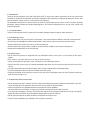
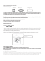
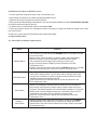
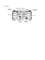
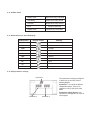
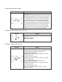
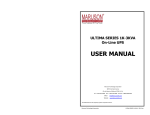
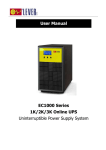
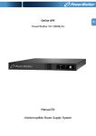
2
W Y
ar e
ra a
nt r
y
Table of contents
1. Introduction
1-1. Transportation
1-2. Preliminary Steps
1-3. Initial Setup
1-4. Important Safety Instructions
1-5. Maintenance, Service and Faults
2. Operation
2.1 Unpacking and inspection
2.2 UPS front and rear panel views
2.3 Installation Procedure
2.4 Forza Tracker monitoring software
3. Advanced operation
3.1 Description of buttons and functions
3.2 LCD Panel
3.3 Audible alarm
3.4 Abreviations on the LCD display
3.5 UPS parameter settings
3.6 Operating mode description
3.7 Fault codes
3.8 Warning indicators
4. Troubleshooting
5. Storage and maintenance
6. Technical specifications
1. Introduction
Thank you for purchasing the Forza Atlas 3000 Online UPS. To enjoy all the features and benefits of this unit, please read
and follow all installation and operation instructions thoroughly before unpacking, installing or operating this device. After
you have read this manual, keep it in a safe place for future reference.
The information contained in this manual covers the 3000 VA uninterruptible power system, its basic functions, operating
procedures, options available and troubleshooting guide. It also includes information on how to ship, store, handle, and
install the equipment.
1-1. Transportation
• Make sure to transport the UPS system only in the original package to protect it against shock and impact.
1-2. Preliminary steps
• Water condensation may occur if the UPS is unpacked in a very cold environment and then moved to a warmer location.
• The UPS must be thoroughly dry before being installed. Failure to do so may increase the risk of electric shock.
• Do not install the UPS system near water or in moist environments.
• Do not install the UPS system where it would be exposed to direct sunlight or near a heater or heating vent.
• Do not block ventilation holes in the UPS housing.
1-3. Initial setup
• Do not connect appliances or equipment that may overload the UPS system (such as a laser printer) to the output
sockets.
• Place cables in such a way that no one can step on or trip over them.
• Do not connect domestic appliances, such as hair dryers, to the UPS output sockets.
• Connect the UPS system only to an earthed shockproof outlet which must be easily accessible and close to the UPS
system.
• Use CE-marked cables for connections between mains, the UPS and equipment (shockproof outlet).
• Use CE-marked power cables to connect the loads to the UPS system.
• During the installation of this equipment, make sure that the sum of the leakage currents of the UPS and the connected
loads shall not exceed 3.5 mA.
1-4. Important safety instructions
• Do not disconnect the mains cable on the UPS system or the building wiring outlet (shockproof socket outlet) at any time,
since this would cancel the protective earth of the UPS system and of all connected loads.
• Connect the UPS only to a grounded socket that meets electrical safety guidelines.
Locate the UPS near a wall socket. Do not use an extension cord between the UPS and the socket.
• In the event of an emergency, press the OFF/Enter button and disconnect the power cord from the AC mains to properly
disable the UPS. Do not allow any kind of liquid or foreign object to enter this UPS unit.
• Do not place beverages or any other containers with liquid on or nearby the unit.
• The UPS can be operated by any individuals with no previous experience.
1-5. Maintenance, service and faults
• The voltage used by this UPS may be hazardous. The unit contains no user serviceable parts; do not attempt to
disassemble the unit. Only qualified service technicians can perform maintenance on the unit. Failure to adhere to this
could cause personal injury or equipment malfunction and void the warranty.
• Caution - risk of electric shock. Even after the unit is disconnected from the mains, components inside the UPS system
are still connected to the battery packs which are potentially dangerous.
• Before carrying out any kind of service and/or maintenance, disconnect the batteries and verify that no current is
present and no hazardous voltage exists in the terminals of high capacity capacitors, such as BUS-capacitors. Servicing
of batteries should be performed or supervised by experts who possess the knowledge to closely follow all required
precautions.
• Caution: potentially hazardous voltages from the battery can still be present even after disconnecting the UPS from the
AC mains. Therefore, the positive and negative terminals of the battery shall de disconnected prior to performing any
maintenance or repair inside the unit.
• A battery can present the risk of short-circuit current and electrical shock. The following precautions should be taken:
- remove wristwatches, rings and other metal objects
- use only tools with insulated grips and handles.
• When replacing the battery, make sure to use the same type and number of sealed lead-acid batteries specified.
• Do not dispose of batteries in a fire. Batteries may explode if exposed to high temperatures.
• Never try to open a battery. The cell contains a toxic electrolyte which is harmful to the skin and eyes.
• Please replace the fuse only with the same type and amperage in order to avoid fire hazards.
• Do not dismantle the UPS system.
2. OPERATION
2-1. Unpacking and inspection
Remove the UPS from its package and make sure that all the following items are included:
• One UPS unit
• One user manual
• One monitoring software CD (ForzaTracker)
• One USB cable
• Warranty certificate
Carefully inspect the UPS to check for any damages that may have occurred during shipping. Should any evidence of
damage be found or if some parts are missing, do not turn the UPS on; you must immediately notify the carrier or dealer
where you purchased the unit.
2-2. UPS front and rear panel views
UPS front view picture
Rear panel view
1. Programmable outlets: connect to non-critical loads.
2. Output receptacles: connect to high critical loads.
3. AC input
4. Input circuit breaker
5. Network/Fax/Modem surge protection
6. Emergency power off (EPO) connector
7. USB communication port
8. RS-232 communication port
9. SNMP intelligent slot
10. Output terminal
11. Output circuit breaker
12. Input terminal
2.3. Installation procedure
Choose location
Install the UPS unit in any protected environment that provides adequate airflow around the unit, and free from excessive
dust, corrosive fumes and conductive contaminants. Do not operate your UPS in an environment where the ambient
temperature or humidity is high. For best performance, keep the indoor temperature between 0° C and 40° C. Place the
UPS unit at least 20 cm away from monitors to avoid interference.
Step 1: UPS input connection
Plug the UPS into a two-pole, three-wire, grounded receptacle only. Avoid using extension cords.
• For 200/208/220/230/240VAC models: The power cord is supplied in the UPS package.
• For 100/110/115/120/127VAC models: The power cord is attached to the UPS. The input plug is a NEMA L5-130P.
Note: Check if the site wiring fault indicator lights up in LCD panel. It will be illuminated when the UPS is plugged into an
improperly wired utility power outlet (refer to the troubleshooting section). A circuit breaker (40A) must also be provided
between the mains and AC input.
Step 2: UPS output connection
• For socket-type outputs, there two kinds of outputs: programmable outlets and general outlets. Connect non-critical
devices to the programmable outlets and critical devices to the general outlets. During power failure, you may extend
the backup time to critical devices by setting shorter backup time for non-critical devices.
• For terminal-type input or outputs, please follow the steps below for the wiring configuration:
a) Remove the terminal block cover by unscrewing the two screws.
b) We recommend using an AWG 14 or 2.1mm2 power cord, a AWG12-10 or 3.3mm2-5.3mm2 power cord for
the NEMA type.
c) Once the wiring configuration is complete, verify that the wires are securely attached.
d) Finally, replace the terminal cover and secure it using the screws.
Step 3: Communication connection
Communication port:
USB port
RS-232 port
Intelligent slot
To allow for unattended UPS shutdown/start-up and status monitoring, connect one end of the communication cable to
the USB/RS-232 port, and the other end to the communication port of your PC. With the monitoring software installed, you
can schedule UPS shutdown/start-up and monitor UPS status through PC.
The UPS is equipped with intelligent slot perfect for either SNMP or AS400 card. When installing either SNMP or AS400
card in the UPS, it will provide advanced communication and monitoring options.
Note: The USB port and RS-232 port cannot be used at the same time.
Step 4: Connect the network surge protection
The UPS has two network cable jacks for network lines
Network/Fax/Phone port
Entrada
Salida
• Connect a single line modem/phone/fax cable into the network surge-protection “IN” jack on the rear panel of the UPS.
• Connect a network cable from the OUT jack on the rear of the UPS to a port on a PC or network device such as a route.
Step 5: Disabling and enabling the EPO function
Keep pins 1 and 2 closed for UPS normal operation. To activate EPO feature, remove the wire between pin 1 and 2.
Closed for UPS normal
operation.
Step 6: Turning on the UPS
Press the ON/Mute button on the front panel for two seconds to power on the UPS.
Note: The battery charges fully during the first five hours of normal operation. Do not expect full battery run capability during
this initial charge period.
2-4. ForzaTracker monitoring software
ForzaTracker is a new generation of UPS monitoring software, which provides user-friendly interface to monitor and control
your UPS system. This unique software provides safe auto-shutdown for multi-computer systems during power failures. With
this software, users can monitor and control any UPS on the same LAN no matter how far they might be from the UPS.
Installation procedure for Windows users:
1. Use the supplied CD or go to the website: http://www.forzaups.com.
2. After clicking the software icon, choose the required operation system.
3. Follow the on-screen instructions to install the software.
4. When you finished downloading all required files, enter the serial No (installation password): 5242-87f6-64re-di8d-986u
to install the software (include the hyphens).
5. In order to access as Administrator, input the password: 111296.
6. When your computer restarts, the management software will appear as a light blue round icon located in the system
tray, near the clock.
For Mac users, please refer to the ForzaTracker QIG inside the Mac folder.
3. Advanced operation
3-1. Description of buttons and functions
Button
ON/Mute Button
OFF/Enter Button
Function
Turn on the UPS: Press and hold the ON/Mute button for at least 2 seconds
to turn on the UPS.
Mute the alarm: When the UPS is on battery mode, press and hold this
button for at least 5 seconds to disable or enable the alarm system.
This command would not apply when warnings or errors occur.
Up key: Press this button to display previous selection in the UPS
configuration menu.
Switch to UPS self-test mode: Press and hold ON/Mute button for 5 seconds
to perform the self-test in AC mode, ECO mode, or converter mode.
Turn off the UPS: Press and hold this button for at least 2 seconds to turn
off the UPS in battery mode. The UPS will remain in standby mode under
normal power conditions or transfer to Bypass mode provided it has been
enabled previously by pressing this button.
Confirm selection key: Press this button to confirm the selection in the
UPS configuration menu.
Select Button
Switch LCD message: Press this button to change the LCD message for
input voltage, input frequency, battery voltage, output voltage and output
frequency. The default display will be restored when pausing for 10 seconds.
Setting mode: Press and hold this button for 5 seconds to enter the UPS
configuration menu while UPS is in standby or bypass mode.
Down key: Press this button to display the next selection in the UPS
configuration menu.
ON/Mute +
Select Button
Switch to bypass mode: When the utility power is normal, press ON/Mute
and Select buttons simultaneously for 5 seconds to transfer the UPS to
bypass mode. This action will be ineffective if the input voltage is not within
an acceptable range.
3-2. LCD panel
Display
Function
Backup time information
Indicates the remaining backup time in pie chart.
Indicates the remaining backup time in numbers.
H: hour, M: minute, S: second
Fault information
Indicates that the warning and fault occurs
Warning and fault code indicators. The meaning of the codes is listed
in the section below.
Mute operation
Indicates that the UPS alarm is disabled.
Output & battery voltage information
Output voltage, frequency or battery voltage.
VAC: output voltage VDC: battery voltage Hz: frequency
Load information
Load level indicator at 0-25%, 26-50%, 51-75%, and 76-100%
of its capacity
Overload indicator
Indicates the load or the UPS output is short circuited.
Programmable outlet information
Indicates that programmable management outlets are working
Mode operation information
Indicates the UPS is connected to the mains
Indicates the battery is working
Indicates the bypass circuit is working
Indicates the ECO mode is enabled
Indicates the Inverter circuit is working
Indicates the output receptacle is working
Battery information
Battery level indicator at 0-25%, 26-50%, 51-75%, and 76-100%
of its capacity
Battery fault indicator
Low battery level and low voltage indicator
Input & Battery voltage information
Input voltage or frequency or battery voltage indicator.
VAC: Input voltage, VDC: battery voltage, Hz: input frequency
3-3. Audible alarm
Battery mode
Beeps once every 4 seconds
Low battery
Beeps once every second
Overload
Beeps twice every second
Fault
Beeps continuously
Bypass mode
Beeps every 10 seconds
3-4. Abbreviations on the LCD display
Abbreviation
Display content
Meaning
ENA
Enable
DIS
Disable
ESC
Escape
HLS
High line transfer
LLS
Low line transfer
BAT
Battery
CF
Converter
EP
EPO
TP
Temperature
CH
Charger
3-5. UPS parameter settings
Parameter 1
Parameter 2
Parameter 3
Three parameters need to be configured
in order to set up the UPS. Refer to
following diagram.
Parameter 1: it is used for the different
configuration options. There are 10
programs to set up. Refer to the table
below.
Parameter 2 and parameter 3: they
represent the setting options or values of
each program.
01: Output voltage settings
Interface
Setting
Parameter 3: Output voltage
For 200/208/220/230/240 VAC, you may choose any of the
following output voltages in parameter 3:
200: The output voltage is 200VAC
208: The output voltage is 208VAC
220: The output voltage is 220VAC
230: The output voltage is 230VAC
240: The output voltage is 240VAC
For 100/110/150/120/127 VAC, you may choose any of the
following output voltages :
100: The output voltage is 100VAC
110: The output voltage is 110VAC
115: The output voltage is 115VAC
120: The output voltage is 120VAC
127: The output voltage is 127VAC
02: Frequency Converter enable/disable
Interface
Setting
Parameter 2 & 3: Activates or cancels the converter mode
CF ENA: Enable converter mode
CF DIS: Disable converter mode
03: Output frequency settings
Interface
Setting
Parameter 2 & 3: Output frequency setting.
Use this menu to define the initial frequency on battery mode:
BAT 50: The output frequency is set to 50Hz
BAT 60: The output frequency is set to 60Hz
If the converter mode is enabled, the following options
will be available:
CF 50: The output frequency is set to 50Hz
CF 60: The output frequency is set to 60Hz
04: ECO enable/disable
Interface
Setting
Parameter 3: Activates or cancels the ECO mode:
ENA: ECO mode enabled
DIS: ECO mode disabled
05: ECO voltage range settings
Interface
Setting
Parameter 2 & 3: Press the UP or Down key to choose the
acceptable high and low voltage values for the ECO mode.
HLS: High line transfer in ECO mode as set in parameter 2.
For 200/208/220/230/240 VAC, the setting in parameter
3 ranges between +7V and +24V of the nominal voltage.
For 100/110/115/120/127 VAC, the setting in parameter 3
ranges between+3V and +12V of the nominal voltage.
LLS: Low line transfer in ECO mode as set in parameter 2.
For 200/208/220/230/240 VAC, the setting in parameter
3 ranges between-7V and -24V of the nominal voltage.
For 100/110/115/120/127 VAC, the setting in parameter
3 ranges from -3V to -12V of the nominal voltage.
06: Bypass enable/disable when UPS is off
Interface
Setting
Parameter 3: Use it to activate or cancel the Bypass mode.
ENA: Bypass enabled
DIS: Bypass disabled
07: Bypass voltage range setting
Interface
Setting
Parameter 2 & 3: Press the UP or Down key to choose the
acceptable high and low voltage values for Bypass operation
HLS: High voltage adjustment in bypass mode
For 200/208/220/230/240 VAC:
230-264: High voltage setting from 230VAC to 264VAC
as set in parameter 3.
For 100/110/115/120/127 VAC:
120-132: High voltage setting from 120VAC to 132VAC
as set in parameter 3.
LLS: Low voltage adjustment in bypass mode
For 200/208/220/230/240 VAC:
170-220: Low voltage setting from 170VAC to 220VAC
as set in parameter 3.
For 100/110/115/120/127 VAC:
85-115: Low voltage setting from 85VAC to 115VAC
as set in parameter 3
08: Enable/Disable programmable outlets
Interface
Setting
Parameter 3: Activates or cancels the programmable
outlet feature.
ENA: Programmable outlets enabled
DIS: Programmable outlets disabled
09: Backup time setting for programmable outlets
Interface
Setting
Parameter 3: Sets the backup time limits for the
programmable outlets.
0-999: Use this setting to define the programmable outlets
backup time in minutes, from 0-999, in order to connect
non-critical devices on battery mode.
10: Backup time setting for outlets
Interface
Setting
Parameter 3: Sets up backup interval on battery mode
for default outlets.
0-999: Use this setting to define the default outlets backup
interval in minutes, from 0-999, to operate on battery mode.
0: When this parameter is set to “0”, the backup interval will
only last 10 seconds.
999: When this parameter is set to “999”, the backup interval
will be disabled.
00: Exit setting
3-6. Operation mode description
Operating mode
Description
Online mode
When the input voltage is within acceptable range, the UPS
will supply pure and stable AC power to connected loads.
The UPS will also charge the battery in online mode.
ECO mode
Energy saving mode:
When the input voltage is within the voltage regulation range,
the UPS will bypass voltage to loads for energy saving.
LCD display
When input frequency is between 40 Hz and 70 Hz,
Frequency
the UPS can be set at a constant output frequency,
Converter mode 50 Hz or 60 Hz. The UPS will still charge the battery when
operating in this mode.
Battery mode
When the input voltage exceeds the acceptable range or
during a power failure, the UPS will start supplying power
from the battery while the alarm will beep every 4 seconds.
Bypass mode
When input is within acceptable voltage range but the UPS
is overloaded, the UPS will transfer to bypass mode or it can
be manually changed to bypass mode using the front panel
controls. The alarm will sound once every 10 seconds
in this case.
Standby mode
The UPS is powered off and there is no power supplied to
the loads, but batteries can still be charged.
3-7. Fault codes
Fault event
Fault
code
Fault event
Fault
code
Icon
X
Bus start failure
01
Low inverter voltage
13
Bus over
02
Inverter output is short circuited
14
Bus under
03
Battery voltage too high
27
Bus unbalance
04
Battery voltage too low
28
Inverter soft start failure
11
Excessive temperature
41
High inverter voltage
12
Overload
43
X
3-8. Warning indicators
Warning
Icon (flashing)
Alarm
Low battery
Beeps once every second
Overload
Beeps twice every second
Battery not connected
Beeps once every second
Overcharge
Beeps once every second
Site wiring fault
Beeps once every second
EPO enable
Beeps once every second
Over temperature
Beeps once every second
Charger failure
Beeps once every second
Out of bypass voltage range
Beeps once every second
4. Troubleshooting guide
If the UPS system does not operate correctly, use the table below to troubleshoot the problem.
Symptom
Even though the mains supply
is normal, there are no status
indicators or alarms.
Possible cause
Remedy
The AC input cable is not
properly connected.
Check to make sure the power cord is
firmly connected to a AC wall socket
The AC input is connected
Plug the power cord to a wall socket.
to the UPS outlet.
The
icon and the warning code
become illuminated on the
EPO function is enabled
LCD display, and the alarm starts
beeping once every second.
Set the circuit in its closed position
to disable the EPO function
The
and the
icons become Live and neutral
illuminated on the LCD display,
conductors of UPS input
and the alarm starts beeping once are reversed.
every second.
Rotate mains power socket by 180°
and then connect to UPS system
The
and
icons become
illuminated on the LCD display
and the alarm starts beeping
once every second.
The external or internal
battery connection
is incorrect.
Check if all batteries are
properly connected.
Fault code 27 and the
become illuminated on the LCD
display and alarm starts
beeping continuously.
Battery voltage is too high
Contact your dealer or service center
or the charger is fault
Fault code 28 and the
icon become illuminated on the
LCD display and the alarm starts
beeping continuously.
Battery voltage is too low
or the charger fails
Please contact the dealer
or service center
UPS is overloaded
Remove excess loads from UPS output
UPS is overloaded.
Devices connected to the Remove excess loads from the
UPS are fed directly from UPS output
The
and
icons become
utility power via the Bypass
illuminated on the LCD display and
the alarm starts beeping twice
After repetitive overloads, Remove excess loads from the UPS
every second
the UPS is locked in
output first. Shut down the UPS
Bypass mode. Connected completely before restarting the unit
devices are fed directly
once again
from utility power.
Fault code 43 becomes illuminated
along with the
icon on the
LCD display, and the alarm starts
beeping continuously
The UPS shuts down
automatically upon
detecting the overload
condition in the output
Remove excess loads from the UPS
output and restart the unit once again
Symptom
Possible cause
Remedy
Fault code 14 becomes illuminated
along with the icon on the
LCD display, and the alarm starts
beeping continuously.
The UPS shuts down
automatically upon
detecting the overload
condition in the output.
Check the output wiring and
if connected devices are
short-circuited.
Fault code 1, 2, 3, 4, 11, 12, 13
and 41 become illuminated on
the LCD display, and alarm starts
beeping continuously.
A UPS internal fault has
occurred. There are two
possible causes:
1. Power is continued to
be supplied to the load,
but is done directly from
the AC grid via a bypass.
2. Power is no longer
supplied to the load.
Please contact the dealer or
service center.
Battery backup time is shorter
than its nominal value.
Batteries are not fully
charged.
Defective batteries.
Charge the batteries for at least
5 hours and then check their
capacity. If the problem persists,
consult your dealer.
Contact your dealer for
a replacement.
5. Storage and maintenance
The UPS system contains no user-serviceable parts. If the battery service life (3~5 years at 25°C ambient
temperature) has been exceeded, the batteries must be replaced. In this case, please contact your dealer or
service center.
Batteries must not be discarded as regular household waste! As part of the
company’s eco-friendly approach, we encourage you to follow all applicable local
waste regulations to dispose of your used devices and batteries properly.
Storage
Charge the UPS for at least 5 hours before storing the unit. Cover the UPS, and place it upright in a cool, dry location.
During storage, recharge the battery in accordance with the following table:
Storage temperature
Recharge frequency
Runtime
-25°C - 40°C
Every 3 months
1-2 hours
40°C - 45°C
Every 2 months
1-2 hours
6. Specifications
Model
FDC-003K
3000 VA / 2400 W
CAPACITY*
INPUT
Low line transfer
Voltage range
Low line comeback
High line transfer
High line comeback
Frequency range
Phase
Power factor
OUTPUT
Output voltage
AC voltage regulation
Frequency range (synchronized range)
Frequency range (batt. mode)
160VAC / 140VAC / 120VAC / 110VAC ± 5 % or
80VAC / 70VAC / 60VAC / 50VAC ± 5 %
(based on load percentage
100% - 80 % / 80 % - 70 % / 70 - 60 % / 60 % - 0)
High line transfer voltage - 10V
300 VAC ± 5 % or 150 VAC ± 5 %
290 VAC ± 5 % or 145 VAC ± 5 %
40Hz ~ 70 Hz
Single phase with ground
≥ 0.99 @ 220-230 VAC (input voltage)
200/208/220/230/240VAC or 100/110/115/120/127 VAC
± 3% (batt. mode)
47 ~ 53 Hz or 57 ~ 63 Hz
50 Hz ± 0.25 Hz or 60Hz ± 0.3 Hz
100%~110%: audible warning
110%-130%: UPS shuts down in 30 seconds in battery mode
or transfers to bypass mode when utility power is normal.
>130%: UPS shuts down immediately in battery mode
or transfer to bypass mode when utility power is normal
Overload
Current crest ratio
3:1
≤3 % THD (linear load)
≤6 % THD (non-linear load)
Harmonic distortion
Transfer time
AC mode
to batt. mode
Inverter to bypass
Zero
4 ms (typical)
Pure sine wave
Waveform (batt. mode)
EFFICIENCY
AC mode
Battery mode
BATTERY
≤ 4 % THD (linear load)
≤ 7 % THD (non-linear load)
~ 85%
~ 88%
~ 83%
Battery type
Quantity
Recharge time
Charging current
Charging voltage
12 V / 9 Ah
6
4 hours to 90% capacity (typical)
1.0 A (max.)
82.1 VDC ±1%
Dimensions (mm)
Net weight (kg)
421 X 190 X 318
PHYSICAL
Tower case
ENVIRONMENT
Humidity
Noise level
MANAGEMENT
Smart RS-232 or USB
Optional SNMP
28
20-90 % RH @ 0- 40°C (non-condensing)
Less than 45dBA @ 1 meter
Supports Windows® 2000/2003/XP/Vista/2008/7,
Linux, Unix and MAC
Power management from SNMP manager
and web browser
* Derate capacity to 60% of capacity in Frequency converter mode and to 80% when the output voltage
is adjusted to 208VAC.