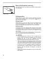
1
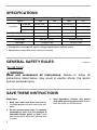
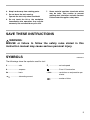
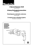
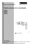
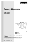
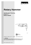
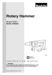
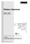
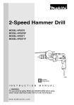
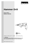
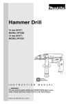
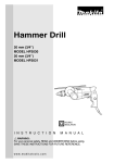
2-Speed Hammer Drill
MODEL HP2050F
MODEL HP2051F
DOUBLE
INSULATION
I N S T R U C T I O N
M A N U A L
WARNING:
For your personal safety, READ and UNDERSTAND before using.
SAVE THESE INSTRUCTIONS FOR FUTURE REFERENCE.
w w w. m a k i t a t o o l s. c o m
SPECIFICATIONS
Model
HP2050F
Speed
HP2051F
High
Low
High
Low
Concrete
20 mm (3/4”)
-
20 mm (3/4”)
-
Steel
8 mm (5/16”)
13 mm (1/2”)
8 mm (5/16”)
13 mm (1/2”)
Wood
25 mm (1”)
40 mm (1-9/16”)
25 mm (1”)
40 mm (1-9/16”)
No load speed (RPM)
0 - 2,900/min.
0 - 1,200/min.
0 - 2,900/min.
0 - 1,200/min.
Blows per minute
0 - 58,000
0 - 24,000
0 - 58,000
0 - 24,000
Capacities
Overall length
362 mm (14-1/4”)
360 mm (14-1/8”)
Net weight
2.3 kg (5.1 lbs)
2.3 kg (5.1 lbs)
• Manufacturer reserves the right to change specifications without notice.
• Specifications may differ from country to country.
GENERAL SAFETY RULES
USA002-2
(For All Tools)
WARNING:
Read and understand all instructions. Failure to follow all
instructions listed below, may result in electric shock, fire and/or
serious personal injury.
SAVE THESE INSTRUCTIONS
Work Area
1. Keep your work area clean and well lit.
Cluttered benches and dark areas invite accidents.
2. Do not operate power tools in explosive
atmospheres, such as in the presence of
flammable liquids, gases, or dust. Power
tools create sparks which may ignite the dust
or fumes.
2
3. Keep bystanders, children, and visitors
away while operating a power tool. Distractions can cause you to lose control.
Electrical Safety
4. Double insulated tools are equipped with
a polarized plug (one blade is wider than
the other.) This plug will fit in a polarized
outlet only one way. If the plug does not fit
fully in the outlet, reverse the plug. If it
still does not fit, contact a qualified electrician to install a polarized outlet. Do not
change the plug in any way. Double insulation
eliminates the need for the three wire
grounded power cord and grounded power
supply system.
5. Avoid body contact with grounded surfaces such as pipes, radiators, ranges and
refrigerators. There is an increased risk of
electric shock if your body is grounded.
6. Do not expose power tools to rain or wet
conditions. Water entering a power tool will
increase the risk of electric shock.
7. Do not abuse the cord. Never use the cord
to carry the tools or pull the plug from an
outlet. Keep cord away from heat, oil,
sharp edges or moving parts. Replace
damaged cords immediately. Damaged
cords increase the risk of electric shock.
8. When operating a power tool outside, use
an outdoor extension cord marked “W-A”
or “W”. These cords are rated for outdoor
use and reduce the risk of electric shock.
Personal Safety
9. Stay alert, watch what you are doing and
use common sense when operating a
power tool. Do not use tool while tired or
under the influence of drugs, alcohol, or
medication. A moment of inattention while
operating power tools may result in serious
personal injury.
10. Dress properly. Do not wear loose clothing or jewelry. Contain long hair. Keep
your hair, clothing, and gloves away from
moving parts. Loose clothes, jewelry, or long
hair can be caught in moving parts.
11. Avoid accidental starting. Be sure switch
is off before plugging in. Carrying tools with
your finger on the switch or plugging in tools
that have the switch on invites accidents.
12. Remove adjusting keys or wrenches
before turning the tool on. A wrench or a
key that is left attached to a rotating part of
the tool may result in personal injury.
13. Do not overreach. Keep proper footing
and balance at all times. Proper footing and
balance enables better control of the tool in
unexpected situations.
14. Use safety equipment. Always wear eye
protection. Dust mask, non-skid safety
shoes, hard hat, or hearing protection must
be used for appropriate conditions. Ordinary
eye or sun glasses are NOT eye protection.
Tool Use and Care
15. Use clamps or other practical way to
secure and support the workpiece to a
stable platform. Holding the work by hand or
against your body is unstable and may lead
to loss of control.
16. Do not force tool. Use the correct tool for
your application. The correct tool will do the
job better and safer at the rate for which it is
designed.
17. Do not use tool if switch does not turn it
on or off. Any tool that cannot be controlled
with the switch is dangerous and must be
repaired.
18. Disconnect the plug from the power
source before making any adjustments,
changing accessories, or storing the tool.
Such preventive safety measures reduce the
risk of starting the tool accidentally.
19. Store idle tools out of reach of children
and other untrained persons. Tools are
dangerous in the hands of untrained users.
20. Maintain tools with care. Keep cutting
tools sharp and clean. Properly maintained
tools with sharp cutting edges are less likely
to bind and are easier to control.
3
21. Check for misalignment or binding of
moving parts, breakage of parts, and any
other condition that may affect the tools
operation. If damaged, have the tool serviced before using. Many accidents are
caused by poorly maintained tools.
SERVICE
22. Use only accessories that are recommended by the manufacturer for your
model. Accessories that may be suitable for
one tool, may become hazardous when used
on another tool.
24. When servicing a tool, use only identical
replacement parts. Follow instructions in
the Maintenance section of this manual.
Use of unauthorized parts or failure to follow
Maintenance instructions may create a risk of
electric shock or injury.
23. Tool service must be performed only by
qualified repair personnel. Service or maintenance performed by unqualified personnel
could result in a risk of injury.
USE PROPER EXTENSION CORD: Make sure your extension cord is in good condition.
When using an extension cord, be sure to use one heavy enough to carry the current your
product will draw. An undersized cord will cause a drop in line voltage resulting in loss of
power and overheating. Table 1 shows the correct size to use depending on cord length and
nameplate ampere rating. If in doubt, use the next heavier gage. The smaller the gage number, the heavier the cord.
Table 1: Minimum gage for cord
Volts
120 V
Ampere Rating
More Than
Not More Than
0
6
10
12
6
10
12
16
25 ft.
Total length of cord in feet
50 ft.
100 ft.
150 ft.
AWG
18
18
16
14
SPECIFIC SAFETY RULES
16
16
16
12
16
14
14
12
14
12
Not Recommended
USB002-2
DO NOT let comfort or familiarity with product (gained from
repeated use) replace strict adherence to hammer drill safety
rules. If you use this tool unsafely or incorrectly, you can suffer
serious personal injury.
1. Hold tools by insulated gripping surfaces
when performing an operation where the
cutting tool may contact hidden wiring or
its own cord. Contact with a “live” wire will
make exposed metal parts of the tool “live”
and shock the operator.
4
2. Always be sure you have a firm footing. Be
sure no one is below when using the tool in
high locations.
3. Hold the tool firmly with both hands.
Always use the side grip.
4. Keep hands away from rotating parts.
5. Do not leave the tool running.
Operate the tool only when hand-held.
7. Some material contains chemicals which
may be toxic. Take caution to prevent
working dust inhalation and skin contact.
Follow material supplier safety data.
6. Do not touch the bit or the workpiece
immediately after operation; they may be
extremely hot and could burn your skin.
SAVE THESE INSTRUCTIONS
WARNING:
MISUSE or failure to follow the safety rules stated in this
instruction manual may cause serious personal injury.
SYMBOLS
USD202-2
The followings show the symbols used for tool.
V ....................... volts
A ....................... amperes
Hz ..................... hertz
n ....................no load speed
˚
....................Class II Construction
.../min................revolutions or reciprocation per
minute
................ alternating current
................number of blow
5
FUNCTIONAL
DESCRIPTION
•
002990
CAUTION:
Always be sure that the tool is switched off and
unplugged before adjusting or checking function on the
tool.
Switch action
1
4
3
•
5
2
•
1.
2.
3.
4.
5.
Lock button
Speed control screw
Switch trigger
Higher
Lower
CAUTION:
Before plugging in the tool, always check to see that the
switch trigger actuates properly and returns to the “OFF”
position when released.
Switch can be locked in “ON” position for ease of
operator comfort during extended use. Apply caution
when locking tool in “ON” position and maintain firm
grasp on tool.
To start the tool, simply pull the switch trigger. Tool speed is
increased by increasing pressure on the switch trigger.
Release the switch trigger to stop.
For continuous operation, pull the switch trigger and then
push in the lock button.
To stop the tool from the locked position, pull the switch trigger fully, then release it.
A speed control screw is provided so that maximum tool
speed can be limited (variable). Turn the speed control screw
clockwise for higher speed, and counterclockwise for lower
speed.
002689
Lighting up the lamps
•
CAUTION:
Do not look in the light or see the source of light directly.
To turn on the lamp, pull the trigger. Release the trigger to
turn it off.
1
NOTE:
1. Lamp
•
6
Use a dry cloth to wipe the dirt off the lens of lamp. Be
careful not to scratch the lens of lamp, or it may lower the
illumination.
002991
Reversing switch action
This tool has a reversing switch to change the direction of
rotation. Move the reversing switch lever to the
position
(A side) for clockwise rotation or the
position (B side) for
counterclockwise rotation.
A
B
1
•
1. Reversing switch lever
•
002691
CAUTION:
Always check the direction of rotation before operation.
Use the reversing switch only after the tool comes to a
complete stop. Changing the direction of rotation before
the tool stops may damage the tool.
Speed change
1
Two speed ranges can be preselected with the speed
change knob.
2
To change the speed, turn the speed change knob so that
the arrow on the tool body points toward the “I” position on
the knob for low speed or “II” position for high speed.
If it is hard to turn the knob, first turn the chuck slightly in
either direction and then turn the knob again.
1. Arrow
2. Speed change knob
•
•
002692
1
1. Action mode changing lever
CAUTION:
Use the speed change knob only after the tool comes to
a complete stop. Changing the tool speed before the tool
stops may damage the tool.
Always set the speed change knob to the correct
position. If you operate the tool with the speed change
knob positioned halfway between the “I” and “II” position,
the tool may be damaged.
Selecting the action mode
This tool has an action mode change lever. For rotation with
hammering, slide the action mode change lever to the right
( symbol). For rotation only, slide the action mode change
lever to the left ( symbol).
•
CAUTION:
Always slide the action mode change lever all the way to
your desired mode position. If you operate the tool with
the lever positioned halfway between the mode symbols,
the tool may be damaged.
7
ASSEMBLY
•
002693
1
3
Installing side grip (auxiliary handle)
Always use the side grip to ensure operating safety. Install
the side grip so that the teeth on the grip fit in between the
protrusions on the tool barrel.
Then tighten the grip by turning clockwise at the desired
position. It may be swung 360° so as to be secured at any
position.
2
4
1.
2.
3.
4.
CAUTION:
Always be sure that the tool is switched off and
unplugged before carrying out any work on the tool.
Grip base
Side grip (auxiliary handle)
Teeth
Protrusions
Installing or removing drill bit
002694
To install the bit, place it in the chuck as far as it will go.
Tighten the chuck by hand. Place the chuck key in each of
the three holes and tighten clockwise. Be sure to tighten all
three chuck holes evenly.
To remove the bit, turn the chuck key counterclockwise in just
one hole, then loosen the chuck by hand.
1
After using the chuck key, be sure to return to the original
position.
1. Chuck key
002695
1
2
1. Sleeve
2. Ring
8
For Model HP2050F
For Model HP2051F
Hold the ring and turn the sleeve counterclockwise to open
the chuck jaws. Place the bit in the chuck as far as it will go.
Hold the ring firmly and turn the sleeve clockwise to tighten
the chuck.
To remove the bit, hold the ring and turn the sleeve counterclockwise.
002696
1
Depth gauge
The depth gauge is convenient for drilling holes of uniform
depth. Loosen the side grip and insert the depth gauge into
the hole in the side grip. Adjust the depth gauge to the
desired depth and tighten the side grip.
NOTE:
1. Depth gauge
•
The depth gauge cannot be used at the position where
the depth gauge strikes against the tool body.
OPERATION
Hammer drilling operation
•
CAUTION:
There is a tremendous and sudden twisting force
exerted on the tool/bit at the time of hole break-through,
when the hole becomes clogged with chips and
particles, or when striking reinforcing rods embedded in
the concrete. Always use the side grip (auxiliary handle)
and firmly hold the tool by both side grip and switch
handle during operations. Failure to do so may result in
the loss of control of the tool and potentially severe
injury.
When drilling in concrete, granite, tile, etc., move the action
mode changing lever to the position of symbol to use
“rotation with hammering” action.
Be sure to use a tungsten-carbide tipped bit.
Position the bit at the desired location for the hole, then pull
the switch trigger. Do not force the tool. Light pressure gives
best results. Keep the tool in position and prevent it from slipping away from the hole.
Do not apply more pressure when the hole becomes clogged
with chips or particles. Instead, run the tool at an idle, then
remove the bit partially from the hole. By repeating this several times, the hole will be cleaned out and normal drilling
may be resumed.
9
001302
Blow-out bulb (optional accessory)
After drilling the hole, use the blow-out bulb to clean the dust
out of the hole.
1
1. Blow-out bulb
Drilling operation
When drilling in wood, metal or plastic materials, move the
action mode changing lever to the position of symbol to
use “rotation only” action.
Drilling in wood
When drilling in wood, the best results are obtained with
wood drills equipped with a guide screw. The guide screw
makes drilling easier by pulling the bit into the workpiece.
Drilling in metal
To prevent the bit from slipping when starting a hole, make
an indentation with a center-punch and hammer at the point
to be drilled. Place the point of the bit in the indentation and
start drilling.
Use a cutting lubricant when drilling metals. The exceptions
are iron and brass which should be drilled dry.
•
10
CAUTION:
Pressing excessively on the tool will not speed up the
drilling. In fact, this excessive pressure will only serve to
damage the tip of your bit, decrease the tool
performance and shorten the service life of the tool.
•
There is a tremendous force exerted on the tool/bit at the
time of hole break through. Hold the tool firmly and exert
care when the bit begins to break through the workpiece.
•
A stuck bit can be removed simply by setting the
reversing switch to reverse rotation in order to back out.
However, the tool may back out abruptly if you do not
hold it firmly.
•
Always secure small workpieces in a vise or similar holddown device.
MAINTENANCE
•
002697
1
1. Vent holes
CAUTION:
Always be sure that the tool is switched off and
unplugged before attempting to perform inspection or
maintenance.
Cleaning vent holes
The tool and its air vents have to be kept clean. Regularly
clean the tool’s air vents or whenever the vents start to
become obstructed.
To maintain product SAFETY and RELIABILITY, repairs, carbon brush inspection and replacement, any other maintenance or adjustment should be performed by Makita
Authorized or Factory Service Centers, always using Makita
replacement parts.
ACCESSORIES
•
CAUTION:
These accessories or attachments are recommended for
use with your Makita tool specified in this manual. The
use of any other accessories or attachments might
present a risk of injury to persons. Only use accessory
or attachment for its stated purpose.
If you need any assistance for more details regarding these
accessories, ask your local Makita service center.
•
Drill bits
•
Hammer drill bits
•
Hole saws
•
Blow-out bulb
•
Safety goggles
•
Chuck key
•
Grip assembly
•
Depth gauge
•
Plastic carrying case
11
Memo
12
Cut
First-Class
Postage
Required
Post Office will
not deliver
without proper
postage.
Makita U.S.A., Inc.
14930 Northam Street
La Mirada, CA 90638-5753
Fold
13
MAIL THIS PORTION
Your answers to the following questions are appreciated.
1. This product was purchased from:
3. How did you learn about this product:
Other (
Magazine
Radio
Hardware/Lumber Store
From Dealer
Exhibition
Tool Distributor
Newspaper
From Friend
Industrial Supply
Store Display
Previous Usage
Construction Supply
Catalog
Other (
Home Center
)
2. Use of the product is intended for:
)
4. Most favored points are:
Construction Trade
Design
Repair Service
Industrial Maintenance
Features
Durability
Home Maintenance
Size
Power
Hobby
Price
Other (
Other (
)
)
Makita Brand
5. Any comments:
Paste
MODEL NO.
DAY
YEAR
SERIAL NO.
SEX
STATUS
INTL.
LAST NAME / COMPANY NAME
Married Single
M
F
STREET ADRESS
Paste
MONTH
Paste
Paste
Paste
Paste
DATE PURCHASED
Under 19
AREA
CODE
PHONE
20-29
30-39
Paste
AGE:
ZIP CODE
40-49
50-60
Over 60
Paste
Paste
STATE
Paste
CITY
Paste
Paste
BE SURE TO COMPLETE THE CUSTOMER’S PORTION OF THIS FORM AND RETAIN FOR YOUR RECORDS.
Please return this portion by facsimile or mail.
14
Facsimile No: (714) 522-8133
Paste
Paste
Paste
Paste
Paste
Paste
Paste
Paste
FACTORY SERVICE CENTERS
1-800-4-MAKITA
RETAIN THIS PORTION FOR YOUR RECORDS
ARIZONA
3707 E. Broadway Rd., Ste. 6
Phoenix, AZ 85040
(602) 437-2850
FLORIDA
750 East Sample Road
Pompano Beach, FL 33064
(954) 781-6333
MISSOURI
9876 Watson Road
St. Louis, MO 63126-2221
(314) 909-9889
PENNSYLVANIA
1704 Babcock Blvd.
Pittsburgh, PA 1509
(412) 822-7370
CALIFORNIA
41850 Christy St.
Fremont, CA 94538-5107
(510) 657-9881
GEORGIA
4680 River Green Parkway NW
Duluth, GA 30096
(770) 476-8911
NEBRASKA
4129 S. 84th St.
Omaha, NE 68127
(402) 597-2925
PUERTO RICO
200 Guayama St.
Hato Rey, PR 00917
(787) 250-8776
ILLINOIS
1450 Feehanville Dr.
Mt. Prospect, IL 60056-6011
(847) 297-3100
NEVADA
3375 S. Decatur Blvd.
Suites. 22 - 24
Las Vegas, NV 89102
(702) 368-4277
TENNESSEE
1120 Elm Hill P.
Suile 170 Nashville, TN 372
(615) 248-3321
14930 Northam St.
La Mirada, CA 90638-5753
(714) 522-8088
1970 Fulton Avenue
Sacramento, CA 95825
(916) 482-5197
7674 Clairemont Mesa Blvd.
San Diego, CA 92111
(858) 278-4471
16735 Saticoy St., Ste. 105
Van Nuys, CA 91406
(818) 782-2440
COLORADO
11839 E. 51st Ave.
Denver, CO 80239-2709
(303) 371-2850
MARYLAND
7397 Washington Boulevard,
Suite 104 Elkridge, MD 21075
(410) 796-4401
MASSACHUSETTS
232 Providence Hwy.
Westwood, MA 02090
(781) 461-9754
MINNESOTA
6427 Penn Ave. South
Richfield, MN 55423
(612) 869-5199
NEW JERSEY
251 Herrod Blvd.
Dayton, NJ 08810-1539
(609) 655-1212
NEW YORK
4917 Genessee Street
Cheektowaga, NY 14225
(716) 685-9503
OREGON
828 19th Avenue, N.W.
Portland, OR 97209
(503) 222-1823
TEXAS
12801 Stemmons Fwy Ste. 809
Farmers Branch, TX 75234
(972) 243-1150
12701 Directors Dr.
Stafford, TX 77477-3701
(281) 565-8665
3453 IH-35 North, Ste. 101
San Antonio, TX 78219
(210) 228-0676
WISCONSIN
Lincoln Plaza Shopping Ctr.
2245 S. 108th St. West Allis, WI
53227
(414) 541-4776
CUSTOMER’S RECORD
When you need service: Send
complete tool (prepaid) to one
of the Makita Factory Service
Centers listed, or to an Authorized
Makita Service Center. Be sure
to attach a letter to the outside of
the carton detailing the problem
with your tool.
Date Purchased
Dealer’s Name & Address
Model No.
Serial No.
15
WARNING
Some dust created by power sanding, sawing, grinding, drilling, and other
construction activities contains chemicals known to the State of California
to cause cancer, birth defects or other reproductive harm. Some examples
of these chemicals are:
• lead from lead-based paints,
• crystalline silica from bricks and cement and other masonry products, and
• arsenic and chromium from chemically-treated lumber.
Your risk from these exposures varies, depending on how often you do this
type of work. To reduce your exposure to these chemicals: work in a well
ventilated area, and work with approved safety equipment, such as those
dust masks that are specially designed to filter out microscopic particles.
MAKITA LIMITED ONE YEAR WARRANTY
Warranty Policy
Every Makita tool is thoroughly inspected and tested before leaving the factory. It is warranted to be free of
defects from workmanship and materials for the period of ONE YEAR from the date of original purchase.
Should any trouble develop during this one year period, return the COMPLETE tool, freight prepaid, to one of
Makita’s Factory or Authorized Service Centers. If inspection shows the trouble is caused by defective
workmanship or material, Makita will repair (or at our option, replace) without charge.
This Warranty does not apply where:
• repairs have been made or attempted by others:
• repairs are required because of normal wear and tear:
• the tool has been abused, misused or improperly maintained:
• alterations have been made to the tool.
IN NO EVENT SHALL MAKITA BE LIABLE FOR ANY INDIRECT, INCIDENTAL OR CONSEQUENTIAL
DAMAGES FROM THE SALE OR USE OF THE PRODUCT. THIS DISCLAIMER APPLIES BOTH DURING
AND AFTER THE TERM OF THIS WARRANTY.
MAKITA DISCLAIMS LIABILITY FOR ANY IMPLIED WARRANTIES, INCLUDING IMPLIED WARRANTIES OF
“MERCHANTABILITY” AND “FITNESS FOR A SPECIFIC PURPOSE,” AFTER THE ONE YEAR TERM OF THIS
WARRANTY.
This Warranty gives you specific legal rights, and you may also have other rights which vary from state to state.
Some states do not allow the exclusion or limitation of incidental or consequential damages, so the above
limitation or exclusion may not apply to you. Some states do not allow limitation on how long an implied
warranty lasts, so the above limitation may not apply to you.
Makita Corporation
Anjo, Aichi, Japan
Made in China
Nan Zi Road, Kunshan Export Processing Zone Jiangsu, P.R. China
884428-971