1
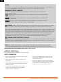
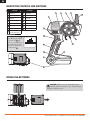
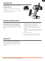
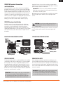
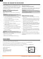
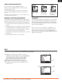
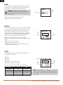
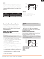
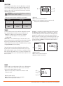
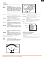
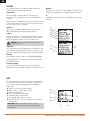
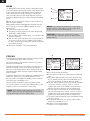
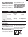
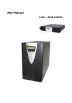
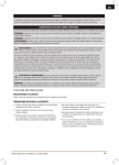
DX4C
4-Channel 2.4GHz DSMR™ System
Instruction Manual
Bedienungsanleitung
Manuel d’utilisation
Manuale di istruzioni
EN
NOTICE
All instructions, warranties and other collateral documents are subject to change at the sole discretion of Horizon Hobby, LLC.
For up-to-date product literature, visit horizonhobby.com and click on the support tab for this Product.
MEANING OF SPECIAL LANGUAGE
The following terms are used throughout the product literature to indicate various levels of potential harm
when operating this product:
NOTICE: Procedures, which if not properly followed, create a possibility of physical property damage AND little
or no possibility of injury.
CAUTION: Procedures, which if not properly followed, create the probability of physical property damage AND
a possibility of serious injury.
WARNING: Procedures, which if not properly followed, create the probability of property damage, collateral
damage and serious injury OR create a high probability of superficial injury.
WARNING: Read the ENTIRE instruction manual to become familiar with the features of the product before operating.
Failure to operate the product correctly can result in damage to the product, personal property and cause serious injury.
This is a sophisticated hobby product. It must be operated with caution and common sense and requires some basic mechanical
ability. Failure to operate this product in a safe and responsible manner could result in injury or damage to the product or other
property. This product is not intended for use by children without direct adult supervision. Do not attempt disassembly, use with
incompatible components or augment product in any way without the approval of Horizon Hobby, LLC. This manual contains
instructions for safety, operation and maintenance. It is essential to read and follow all the instructions and warnings in
the manual, prior to assembly, setup or use, in order to operate correctly and avoid damage or serious injury.
WARNING AGAINST COUNTERFEIT PRODUCTS
Always purchase from a Horizon Hobby, LLC authorized dealer to ensure authentic high-quality Spektrum product. Horizon Hobby,
LLC disclaims all support and warranty with regards, but not limited to, compatibility and performance of counterfeit products
or products claiming compatibility with DSM or Spektrum.
NOTICE: This product is only intended for use with unmanned, hobby-grade, remote-controlled vehicles and aircraft.
Horizon Hobby disclaims all liability outside of the intended purpose and will not provide warranty service related thereto.
Age Recommendation: Not for Children under 14 years. This is not a toy.
WARRANTY REGISTRATION
Visit community.spektrumrc.com today to register your product.
SAFETY PRECAUTIONS
• Always ensure all batteries have been properly charged
prior to using the model.
• Always check all servos and their connections prior
to each run.
• Never operate your model near spectators, parking areas
or any other area that could result in injury to people or
damage of property.
• Never point the transmitter antenna directly toward
the model. The radiation pattern from the tip of the
antenna is inherently low.
• If at any time during the operation of your model you
observe any erratic or abnormal operation, immediately
stop operation of your model until the cause of the
problem has been ascertained and corrected.
• Never operate your model during adverse weather
conditions. Poor visibility can cause disorientation
and loss of control of your model.
SPEKTRUM DX4C • TRANSMITTER INSTRUCTION MANUAL
EN
TABLE OF CONTENTS
Identifying Controls and Switches ..................................4
Installing Batteries........................................................4
the Rubber Grip ...........................................................5
Raceware Firmware Updates ........................................5
ModelMatch ................................................................5
Warning screens ..........................................................6
Receiver Compatibility ..................................................6
AVC – Active Vehicle Control ........................................6
Aux channels ...............................................................6
Electric Vehicle Installation ............................................7
Nitro Vehicle Installation................................................7
SRS410 Failsafe ..........................................................7
SRS4210 Failsafe ........................................................7
Binding the Transmitter and Receiver ............................8
Main Screen ................................................................8
Using the Rolling Selector .............................................9
Individual Direction Adjustments....................................9
List .............................................................................9
Press ..........................................................................9
Roll .............................................................................9
Hold ............................................................................9
Model........................................................................10
Reverse .....................................................................10
Travel ........................................................................10
Expo .........................................................................11
Sub-Trim ...................................................................12
Timer .......................................................................12
Name ........................................................................12
Switch .......................................................................13
System .....................................................................14
Copy .........................................................................14
Reset ........................................................................15
Active Vehicle Control (AVC) ........................................15
Mixing .......................................................................16
Steer Mix...................................................................16
About ........................................................................17
Troubleshooting Guide ................................................17
1-Year Limited warranty .............................................18
WARRANTY SERVICES ................................................18
FCC Information .........................................................19
Antenna Separation Distance ......................................19
IC Information ............................................................20
Compliance Information for the European Union ...........20
Declaration of Conformity ...........................................20
CONTENTS
SYSTEM FEATURES
The DX4C radio system is supplied with the following:
• One-touch easy-to-use programming
• DX4C Transmitter
• Programmable Up or Down timers
• SRS4210 Receiver (SPMSRS4210)
• 56 (high) x 64 (wide) high-resolution dot-matrix screen
• Bind Plug (SPM6802)
• 20-model memory
• Grip Set (SPM9006)
• Travel adjust
• Exponential
• Steering mix
• Programmable mix
• AVC – Active Vehicle Control
SPEKTRUM DX4C • TRANSMITTER INSTRUCTION MANUAL
3
EN
IDENTIFYING CONTROLS AND SWITCHES
Function
Function
A
Button A
I
Rubber Grip
B
Button B
J
Power Switch
C
Button C
K
Power LED
D
Button D
L
Battery Cover
E
Button E
M
Throttle Trigger
F
LCD Screen
N
Steering Wheel
G
Roller Selector
O
Antenna
H
Memory Card Port
(under rubber grip)
A
B
C
D
O
F
G
E
Press the power switch J to
power ON the transmitter.
The Power LED K will
come on, a Spektrum logo
screen will show, then the
Main Screen will show on
the LCD screen F .
N
M
H
I
K
J
L
INSTALLING BATTERIES
CAUTION: NEVER remove the transmitter batteries
while the model is powered on. Loss of model control,
damage or injury may occur.
SPEKTRUM DX4C • TRANSMITTER INSTRUCTION MANUAL
EN
THE RUBBER GRIP
This transmitter includes 3 sizes of grips. The medium-size grip
is installed at the factory.
To change the rubber grip
1. Lift the edge of the grip and pull the grip away from the
handle.
2. Align the tabs on the new grip with the slots in the handle.
3. Press the grip against the handle.
RACEWARE FIRMWARE UPDATES
The DX4C features an SD card reader, enabling you to update
the transmitter when RaceWare™ firmware updates are
available. Register your transmitter at www.SpektrumRC.com
to receive the latest information regarding RaceWare firmware
updates. To install RaceWare firmware updates on your DX4C
transmitter:
1. Remove the grip from the back of the transmitter handle.
2. Download the latest RaceWare firmware from
www.SpektrumRC.com to an SD card. The transmitter serial
number can be found by going to the About screen.
3. Install the SD card in the card reader slot on the DX4C
transmitter.
4. Power on the transmitter. A Spektrum logo and an installation
bar will appear. Installation is complete when the Main screen
appears.
5. Power off the transmitter.
6. Remove the SD card from the card slot on the transmitter.
7. Re-install the rubber grip on the transmitter handle.
MODELMATCH
The Spektrum DX4C transmitter features ModelMatch™
technology, preventing you from operating a vehicle when the
wrong model memory is active in the transmitter. If you select
the wrong model memory, the receiver will not respond to
the transmitter.
SPEKTRUM DX4C • TRANSMITTER INSTRUCTION MANUAL
5
EN
WARNING SCREENS
Low Battery Alarm
An alarm will sound and a warning screen will show when the transmitter’s battery power
goes below a set limit. This alarm reminds a user to bring the model under full control, power
off the transmitter and replace batteries. Press the Roller to stop the alarm and go to the Main
Screen.
Set the low battery limit using the System Screen.
Inactivity Alarm
An alarm will sound and a warning screen will show when the transmitter has been left on
(approximately 10 minutes) without control movement. Moving any control will stop the alarm.
This alarm reminds users to power off the transmitter and save battery power.
RECEIVER COMPATIBILITY
• The DX4C transmitter is compatible with Spektrum™ DSMR™, DSM®, DSM2®, and Marine surface receivers.
• The Spektrum SRS4210 DSMR Surface receiver is compatible with all Spektrum DSMR transmitters and is also
backwards compatible with DSM2 transmitters. The SRS4210 receiver is NOT compatible with DSM transmitters.
• The SR410 DSMR receiver is ONLY compatible with DSMR transmitters.
Antenna
Antenna
Bind/Battery Port
Disable
Data
Aux 2 Port
Aux 1 Port
Throttle Port
Steering Port
Aux 2 Port
Aux 1 Port
Throttle Port
Steering Port
Bind/
Battery Port
AVC – ACTIVE VEHICLE CONTROL
AUX CHANNELS
The Spektrum SRS4210 receiver features Active Vehicle
Control™ (AVC™) technology that responds similar to traction
control in full-scale vehicles. In addition to traction control, AVC
technology also increases steering stability during high speed
driving or while driving over rough terrain. As you increase the
AVC sensitivity, the system increases steering stability and
traction control, similar to reducing the amount of steering
rate in a computer transmitter. Reducing the sensitivity value
increases the amount of steering control from the transmitter.
The SRS4210 receiver also enables you to quickly turn AVC on
or off if you participate in organized racing.
The Aux channels can operate as additional servo channels, or
as a power supply for a personal transponder. If AVC technology
is active, only two channels, Steering and Throttle, are
operational. The Aux channels can be used to power a personal
transponder or lights.
If AVC is disabled (see DISABLING THE STABILITY ASSIST
FUNCTION to disable AVC), the Aux channels will operate as
servo channels.
NOTICE: You must use digital servos with the SRS4210
receiver. Using analog servos will reduce the performance of
the system and may cause analog servos to overheat.
SPEKTRUM DX4C • TRANSMITTER INSTRUCTION MANUAL
EN
SRS4210 Receiver Connection
and Installation
Install the Receiver in your vehicle using the included doublesided foam servo tape. Foam servo tape will hold the receiver in
place and help isolate it from vibrations.
You must install the receiver in the vehicle before binding the
transmitter and receiver. The receiver can be mounted flat with
the label up or on its side. When you bind the receiver, the AVC
system automatically detects the orientation of the receiver. The
receiver must be mounted completely flat when in the label-up
orientation or completely perpendicular when mounted on its
side. If the receiver is angled even slightly, AVC may not function
properly. If the orientation of the receiver is changed after
binding, you must then rebind for AVC to function properly.
SR410 Receiver Installation
Install the receiver in your vehicle using double-sided foam
servo tape. Foam servo tape holds the receiver in place and
protects the receiver from vibration. Position the antenna
vertically and away from the vehicle in an antenna tube. The
SR410 and SRS4210 have a coax-style antenna. The last 31mm
of the antenna is the portion that receives the signal from the
transmitter.
ELECTRIC VEHICLE INSTALLATION
IMPORTANT: Do not use hook & loop material to install the
SRS4210 receiver. Using hook & loop material will affect the
performance of the AVC system.
Mount the antenna up and away from the vehicle in an antenna
tube. The higher up the antenna is, the better signal it will
receive.
CAUTION: Do not cut or bend the antenna. Doing so
could damage the antenna, resulting in the loss of
vehicle control.
Mount the antenna up and away from the vehicle in an antenna
tube. The higher up the antenna is, the better signal it will
receive.
NITRO VEHICLE INSTALLATION
To Motor
Battery
Battery
Receiver
Electronic
Speed
Control
Throttle Servo
Steering Servo
Steering Servo
Receiver
SRS410 FAILSAFE
SRS4210 FAILSAFE
The throttle failsafe position is set during binding. In the unlikely
event that the radio link is lost during use, the receiver will drive
the the throttle servo to its pre-programmed failsafe position
(normally full brakes) and all other channels will have no servo
output. If the receiver is turned on prior to turning on the transmitter, the receiver will enter the failsafe mode, driving the the
throttle servo to its preset failsafe position. When the transmitter
is turned on, normal control is resumed.
In the unlikely event that the radio link is lost during use, the
receiver will drive the throttle channel to the neutral position. If
the receiver is powered on prior to turning on the transmitter, the
receiver will enter the failsafe mode, driving the throttle channel
to the neutral position. When the transmitter is turned on, normal
control is resumed.
IMPORTANT: Failsafe activates only in the event that signal
is lost from the transmitter. Failsafe will NOT activate in
the event that receiver battery power decreases below the
recommended minimums or power to the receiver is lost.
SPEKTRUM DX4C • TRANSMITTER INSTRUCTION MANUAL
IMPORTANT: Failsafe activates only in the event that signal
is lost from the transmitter. Failsafe will NOT activate in
the event that receiver battery power decreases below the
recommended minimums or power to the receiver is lost.
7
EN
BINDING THE TRANSMITTER AND RECEIVER
In order to operate, the receiver must be bound to the
transmitter. Binding is the process of programming the receiver
to recognize the GUID (Globally Unique Identifier) code of a single
specific transmitter. When a receiver is bound to a transmitter/
model memory, the receiver will only respond to that specific
transmitter/model memory.
Binding and Calibrating the Receiver
(AVC Receivers Only)
You must calibrate the receiver each time it is placed in bind
mode.
IMPORTANT: The following sequence of steps must be
followed in order for AVC to function properly.
1. Insert the Bind Plug in the BIND port on the receiver.
2. Power on the receiver. The orange LED flashes, indicating
the receiver is in bind mode.
3. Center the ST TRIM and TH TRIM on the transmitter.
4. Put your transmitter in bind mode.
5. The bind process is complete when the orange LED on the
receiver is solid.
6. Pull the transmitter trigger to Full Throttle.
7. Push the transmitter trigger to Full Brake, then return the
trigger to center.
8. Turn the transmitter steering wheel to Full Right.
9. Turn the transmitter steering wheel to Full Left, then return
the steering wheel to center. The orange LED flashes once.
10. Remove the bind plug once the calibration and binding
process is complete.
11. Power off the transmitter.
IMPORTANT: You must rebind the transmitter and receiver
if you:
•
•
•
Change the servo reverse after binding
Change the travel after binding
Want to use the receiver with a different model memory
If you change the servo reversing or travel adjust after binding,
AVC will not work properly.
Disabling the Stability Assist Function
If you participate in organized racing, you may be required to turn
AVC technology off. To turn off AVC technology, insert a second
Bind Plug in the Disable port before binding.
IMPORTANT: You must calibrate the receiver each time it is
placed in bind mode. To activate AVC, see the steps in BINDING
AND CALIBRATING THE RECEIVER.
Binding (All other receivers)
1. With the receiver off, insert the bind plug into the BIND port
in the receiver.
2. Power the receiver through any port. If an ESC is being used,
power on the ESC with the ESC lead plugged in the throttle
channel port. The orange LED will flash continuously, indicating that the receiver is in bind mode.
3. With the throttle channel in the desired preset failsafe
position (generally full brake and neutral steering), initiate the
bind process with your Spektrum transmitter. This stores the
failsafe position. Continue to hold the failsafe position until
the binding process is complete.
4. The LED on the receiver should now be solid, indicating a
successful bind has taken place.
5. When the bind process is complete, remove the bind plug
from the receiver and store it in a convenient place. Failure
to remove the bind plug will result in the receiver going back
into bind mode.
The only time it is necessary to rebind is if different failsafe
positions are desired e.g., servo travel has been reversed after
the initial bind, or if you want to use the receiver with a different
model memory.
MAIN SCREEN
The Main Screen displays information about the selected model such as trim positions, timer, the model selected, battery voltage,
etc. This screen shows the Timer only when activated.
An alarm will sound when the transmitter’s battery voltage goes below the value set in the System Screen.
An alarm will sound when the timer gets to the limit (DOWN) set in the Timer Screen.
While in any screen, press and hold the Rolling Selector for more than 3 seconds to return to the Main Screen.
Throttle (TH) and Steering (ST) trim positions show as blocks in rectangles.
A
B
C
D
E
F
Active Model Memory
Model Name
Transmitter battery voltage
St (Steering) Trim Position
Th (Throttle) Trim Position
Timer
A
B
E
F
C
D
SPEKTRUM DX4C • TRANSMITTER INSTRUCTION MANUAL
EN
USING THE ROLLING SELECTOR
PRESS
ROLL
HOLD
Press the Selector to enter a highlighted function.
Roll the Selector to highlight a function or change settings
and values when selected.
Press and hold the Selector for more than 3 seconds in any
screen to return the display to the List Screen or the Main
Screen.
To Enter, Choose
or Exit a selection.
To move between
options or change
values in an option.
To program, always start with a press on the Selector, then roll,
then press, then roll, and so on.
Hold for 3 seconds
and release to return
to the Main or
Telemetry screen.
INDIVIDUAL DIRECTION ADJUSTMENTS
“Sticky GUI”
In some instances, you may find it necessary to independently
adjust the control directions; for example, if you want more travel
for left steering than right steering, perform the following steps:
In the Travel, Expo, Mixing and Steer Mixing Screens, sticky GUI
(pronounced gooey) makes value adjustment easier. When you
move the channel control (the steering wheel or throttle trigger)
to the desired position and release, the value on the screen for
that side remains highlighted.
1. Scroll to the value you wish to change and press the Rolling
Selector.
2. When both directions are selected, move the control (steering
or throttle) toward the control direction you wish to change.
The selection box moves to the desired direction. You do not
need to hold the control in the desired direction.
3. To change the opposite direction, simply move the control in
that direction.
Move the control the opposite direction to highlight the other
value on the screen. You do not have to hold the control in the
desired position for the value to be changed. Highlight both
values on the screen again by pressing the Rolling Selector twice
with the control centered.
4. Press the Rolling Selector to save the selection.
LIST
The List Screen shows other screens to set programming in the transmitter.
A A dark box around with a clear symbol or text shows
highlighted selection. Available screens are Select, Reverse,
Travel, Expo, Bind, Sub-Trim, Timer, Name, Switch,
System, Copy, Reset, AVC, Mixing and Steer Mix.
B Active Screen name shows at the top of the screen.
C Choosing this arrow will return to the previous screen.
D A small bar shows relative position of highlighted screen
name in the List.
A
B
C
D
SPEKTRUM DX4C • TRANSMITTER INSTRUCTION MANUAL
9
EN
MODEL
Select function opens a model memory for control of a model
or adjustment of saved settings. If you haven’t programmed a
model memory, all settings will be at factory default.
CAUTION: Do NOT change the model in Model
Select while operating a model. Change of the model
interrupts transmitter signal to the receiver and may
cause a crash.
B
A
A Model name (programmable in Name Screen).
B Model memory number (20 available).
REVERSE
The Reverse function (also known as servo reversing) establishes
the servo’s direction relative to the channel’s input (e.g., a right
steering input should result in a right steering angle at the
model). Reverse is available on all channels and is normally the
first function that is checked and adjusted during programming.
Movement of a control or switch is NOT changed. Instead, a
channel’s response to transmitter input is reversed.
A
B
C
Tip: Your model manual may refer to this as changing
transmitter control directions in the Control Test/Reverse Controls
section.
A Box shows around selected text.
B Channels which can be reversed.
C Dark box shows direction servo is set (Normal is shown):
NOR=normal or REV=reverse.
TRAVEL
The Travel function supports precise endpoint adjustments in
each direction for all channels
A
B
C
D
E
Channel
L (left)*
R (right)*
Box shows around selected text.
Adjustable value (from 0 to 150%)
A
D
B
E
C
*Reference chart for options available for each channel:
Channel
Top
Bottom
Steering
L (left)
R (right)
Throttle
B (brake)
F (forward)
Aux 1
H (high)
L (low)
Aux 2
H (high)
L (low)
NOTICE: Always check the control directions at the extents of
travel to be sure the linkages do not bind. Travel values that
are too high will cause binding, which may result in damage
to the vehicle.
SPEKTRUM DX4C • TRANSMITTER INSTRUCTION MANUAL
EN
EXPO
A
The Exponential (Expo) function affects the response rate of the
steering, throttle and/or brake. A positive Steering Expo value, for
example, decreases steering sensitivity around neutral to make it
easier to drive at high speeds in a straight line while still allowing
for maximum turning radius. While sensitivity with positive Expo
is decreased around neutral, it increases the sensitivity near the
end of travel.
D
B
A
B
C
D
E
*Reference chart for options available for each channel:
Channel
Top
Bottom
Steering
L (left)
R (right)
Throttle
B (brake)
F (forward)
Binding the Transmitter and Receiver
In order to operate, the receiver must be bound to the
transmitter. Binding is the process of programming the receiver
to recognize the GUID (Globally Unique Identifier) code of a single
specific transmitter. When a receiver is bound to a transmitter/
model memory, the receiver will only respond to that specific
transmitter/model memory.
Binding and Calibrating the Receiver
(AVC Receivers Only)
You must calibrate the receiver each time it is placed in bind
mode.
IMPORTANT: The following sequence of steps must be
followed in order for AVC to function properly.
1. Insert the Bind Plug in the BIND port on the receiver.
2. Power on the receiver. The orange LED flashes, indicating
the receiver is in bind mode.
3. Center the ST TRIM and TH TRIM on the transmitter.
4. Put your transmitter in bind mode.
5. The bind process is complete when the orange LED on the
receiver is solid.
6. Pull the transmitter trigger to Full Throttle.
7. Push the transmitter trigger to Full Brake, then return the
trigger to center.
8. Turn the transmitter steering wheel to Full Right.
9. Turn the transmitter steering wheel to Full Left, then return
the steering wheel to center. The orange LED flashes once.
10. Remove the bind plug once the calibration and binding
process is complete.
11. Power off the transmitter.
SPEKTRUM DX4C • TRANSMITTER INSTRUCTION MANUAL
E
C
Channel
L (left)*
R (right)*
Box shows around selected text
Adjustable value (from -100% to +100%
(0 is factory default or inhibit))
IMPORTANT: You must rebind the transmitter and receiver
if you:
•
Change the servo reverse after binding
•
Change the travel after binding
•
Want to use the receiver with a different model memory
If you change the servo reversing or travel adjust after binding,
AVC will not work properly.
Disabling the Stability Assist Function
If you participate in organized racing, you may be required to turn
AVC technology off. To turn off AVC technology, insert a second
Bind Plug in the Disable port before binding.
IMPORTANT: You must calibrate the receiver each time it is
placed in bind mode. To activate AVC, see the steps in BINDING
AND CALIBRATING THE RECEIVER.
A
B
C
D
A
B
C
D
E
E
Select Bind when a receiver is prepared for binding.
Active model number
Active model name
Mode
Speed
11
EN
SUB-TRIM
The Sub-Trim function allows electronic adjustment or centering
of each servo to get the servo arm exactly perpendicular to the
servo, or in the exact optimum desired position. Minor sub-trim
values can be used to correct this offset inaccuracy. Sub-trim is
adjustable for all channels.
A
B
C
CAUTION: Use only small sub-trim values so a servo’s
maximum travel is NOT overdriven.
*Reference chart for options available for each channel:
Channel
Description
Steering
L (left)
R (right)
Throttle
B (brake)
F (forward)
Aux 1
H (high)
L (low)
Aux 2
H (high)
L (low)
A Channel
B Box shows around selected text
C Value for servo alignment (varies among channels)
* Range is 0 to 100 in both directions
TIMER
The Timer function supports Up and Down timing. When started
by an assigned button, the time shows on the Main Screen.
Tip: Refer to Switch Screen instructions for assigning
a button to the Timer (Button E on the grip handle is
recommended).
Down timer – is the default timer type. The timer can be set in
10-second increments to count down from 10 minutes. Normally,
this timer is programmed for the length of a race. The timer’s
default setting is 5 minutes runtime for electric (battery capacity)
and gas-powered (fuel-tank capacity).
Start the timer by pressing the assigned timer button. When
the time expires, an alarm will sound (when Buzzer is not set to
OFF) and then begin to count up. To pause or continue the Down
timer, press the timer button once. To reset the Down timer to its
pre-programmed value, press and hold the timer button for more
than 3 seconds.
Up timer - is started by pressing the timer button and counts up
from 00:00 seconds, functioning as a stopwatch. The Up timer
is useful for timing a fuel run to determine fuel mileage/pit stop
strategy. The Up timer can also be used for electric vehicles to
time the run time of a battery pack for determining gear ratio and
setup. To pause or restart the Up timer, press the timer button. To
reset the Up timer to 00:00 press and hold the timer button for
more than 3 seconds.
B
A
C
A Value for timer
B Box shows around selected text
C Options: Inhibit, Down and Up
NAME
Assign a name for a model memory in this screen. 10 characters
can be used to name a model. This name shows on the Main
Screen when an model memory is active.
Tip: You can only change a model name when the model
memory is active.
A Active model memory
B Model Name (10 character spaces available)
C Marker showing selected character
A
B
C
SPEKTRUM DX4C • TRANSMITTER INSTRUCTION MANUAL
EN
SWITCH
The Switch Screen lets you assign 5 available switches to these
special functions:
ST trim
Assigns a switch to adjust center or neutral so steering
tracks straight.
TH trim
Assigns the throttle idle adjustment to switch. Adjust
throttle neutral (idle) position for drag braking or rolling
idle for some models. Decreasing idle can enable a
drag brake. Increasing idle can keep a model rolling
until the brake is used.
Brake
Assigns brake trim to switch. Full brake is the default.
Braking power can be decreased using this trim on
some models.
Aux 1 Lin Assigns channel 3 (Auxiliary) to switch as linear output
(see servo illustration). This allows for proportional
adjustment of servo position. This is particularly useful
for fuel mixture control on gas engines.
Aux 1 2P Assigns channel 3 (Auxiliary) to switch as 2-position output (see servo illustration). This is useful for
forward and reverse transmissions and some 2-speed
transmissions.
Aux 1 3P Assigns channel 3 (Auxiliary 1) to switch as 3-position output (see servo illustration). This is useful for
forward, neutral and reverse transmissions and some
dig transmissions.
Aux 2 Lin Assigns channel 4 (Auxiliary 1) to switch as linear output (see servo illustration). This allows for proportional
adjustment of servo position. This is particularly useful
for fuel mixture control on gas engines.
Aux 2 2P Assigns channel 4 (Auxiliary 2) to switch as 2-position
output (see servo illustration). This is useful for forward
and reverse transmissions and some 2-speed transmissions.
Aux 2 3P Assigns channel 4 (Auxiliary 2) to switch as 3-position output (see servo illustration). This is useful for
forward, neutral and reverse transmissions and some
dig transmissions.
Tip: Reverse and Travel Screens adjust the endpoints and
direction of the Auxiliary channel.
ROSS
ST D/R
Remote start assigned to a switch.
Assigns Steering rate to a switch so a driver can make
on-the-fly steering travel adjustments. Steering rate
limits the amount of travel of the steering servo.
1
1
Assigns the ST Gain to a switch, enabling you to adjust
the sensitivity without using the AVC menu.
TH GAIN
Assigns TH Gain to a switch, enabling you to adjust the
sensitivity without using the AVC menu.
ST/TH GAIN Assigns the ST GAIN and TH GAIN to the same switch,
enabling you to adjust both gain values
simultaneously.
Priority
Assigns the AVC Priority to a switch, enabling you to
adjust the priority without using the AVC menu.
Inhibit
No function assigned to switch.
* LOSI ROSS (Remote Onboard Starting System)
A
B
C
A Box shows around selected text
B Switch letter (see transmitter illustration)
C Function assigned to the switch
Assignment of switches in other screens changes what is shown
in this screen.
The factory default switch assignments are shown here. Reset of
the transmitter returns switch assignments to these functions.
100
Lin (Linear)
1
2
ST GAIN
3
3P (3 position)
2 2P (2 position)
SPEKTRUM DX4C • TRANSMITTER INSTRUCTION MANUAL
13
EN
SYSTEM
The System function lets you adjust transmitter interaction.
Selections affect all saved model memories.
A Username
You can program a username with up to 10 characters.
This name shows on the Main Screen. Username defaults to
Spektrum.
G About....
This shows the release level of the transmitter’s software. Refer
to Memory Card instructions for updating transmitter software.
H
A small bar shows relative position of highlighted screen name
in the list.
In the System screen highlight the Username and press the roller
to access the function. Use the roller to select the position, then
press the roller to access a character.
B RS Port
This sets the port (Bind or Aux (Auxiliary) on the receiver for
ROSS (Remote Onboard Starting System) connection.
C Alert
You can set an alarm to sound when the battery voltage gets to
the limit set with the Alert. The range which can be set is from
0.0V to 6.2V. Battery voltage shows on the Main Screen.
CAUTION: Do not operate a model when the battery
voltage is below 4V.
D Contrast
The contrast function provides adjustment to the brightness ratio
of the lightest to the darkest part of the screen. You can set the
contrast to a value from 0 to 30 (0 is lightest and 30 is darkest).
A
B
C
D
E
F
H
G
E Buzzer
You can adjust sounds in loudness among Off, Low and High.
Buzzer adjustment does not change sound level for Inactivity or
Low Battery warnings.
F Lang (Language)
You can select English, German (Deu.), French (Francais) or
Italian (Italiano) as the language showing on transmitter screens.
COPY
The Copy function shares active model memory settings with a
selected model memory space. This is useful for saving setups
for one model to adjust programming for track conditions or
model setups.
A Active or source model memory number
B Name of active or source model memory
C Box shows selected text
D Name of destination model memory
E Destination model memory Name
F Choosing No returns to the List Screen
G Choosing Yes saves active model settings to the selected
model memory
IMPORTANT: Model information saved in a memory is
erased and overwritten by active model settings using this
Copy function.
A
B
C
D
E
F
G
SPEKTRUM DX4C • TRANSMITTER INSTRUCTION MANUAL
EN
RESET
The Model Reset function restores factory default settings for
the active model memory.
A Choosing No returns to the List Screen.
B Choosing Yes affirms erasing saved settings for the active
model memory and return of factory defaults.
C A box shows around selected text.
A
C
B
IMPORTANT: Model information saved in a memory is
erased when that model memory is copied over or reset to
factory default settings.
ACTIVE VEHICLE CONTROL (AVC)
Options:
A ST Gain
B TH Gain
C Priority
A
1. Select AVC from the LIST menu.
2. Change the State field to ACT .
3. Adjust the ST Gain and/or TH Gain Sensitivity
The default value is 0% (ST Gain and TH Gain OFF). As
the value increases, the AVC steering stability and throttle
management increases.
Adjust the ST Gain until you reach the ideal amount of
steering control. If the front wheels begin to shake, the ST
Gain value is too high. Reduce the ST Gain value until the
front wheels stop shaking. You can assign ST Gain and TH
Gain to the same switch, enabling you to adjust both values
at the same time.
4. Switch: Assigning ST Gain and TH Gain to a switch enables
you to adjust the sensitivity without using the AVC menu. ST
GAIN and TH GAIN can be assigned to the same switch to
adjust both simultaneously.
5. Adjust the Steering Priority
The Priority default value is 0%, meaning AVC is active when
the steering is close to center. As you turn the steering wheel
away from center (neutral), the transmitter controls have
priority over the AVC system. Increasing the Priority value
decreases how active AVC is as the steering wheel is turned
left and right. For example, if you increase Priority to 80%,
you reduce the AVC steering control by 80% at full left or full
right steering. Increasing the Steering Priority enables you to
make tighter turns.
SPEKTRUM DX4C • TRANSMITTER INSTRUCTION MANUAL
B
C
15
EN
MIXING
The Mixing function lets Steering, Throttle or Aux Channel follow
control input made to the Steering, Throttle or Aux channel. When
a mix is enabled and the assigned input control is moved, the
master (primary) channel sends output at the same time the
slave (secondary) channel sends output. Output is sent to the
model in the direction and to the position assigned in the Mixing
Screen.
Tip: You can only select the Aux channel as Slave in this screen
when Steer Mix is inhibited.
Mixing default setting is inhibit (Inh). When anything other than
Inh is selected, you can make additional adjustments on the
Mixing Screen.
A A box shows around selected text.
B The primary or master channel can be either ST (Steering),
TH (Throttle) or AUX (Auxiliary).
C The secondary or Slave channel can be set on ST, TH or Aux
(Channel 3 Auxiliary).
D This rate value sets the amount of slave servo travel and can
be set from -125% to +125%. A negative value results in
the slave channel moving in a direction opposite the direction
of the primary channel.
E Inh must be changed to enter other mixing values.
A
D
E
NOTICE: Before driving a model, always do a check of the
model’s response to mix settings. Raise the vehicle off the
ground so it does not move during testing.
IMPORTANT: A negative value results in the secondary
channel moving in a direction opposite the direction of the
primary channel.
A
STEER MIX
Steer Mix function supports mixing Steering to Auxiliary channel
so the Auxiliary input follows input to Steering.
Steer mix is usually used to manage how much rear steering
follows front steering inputs.
Typically, this mixing function is used with 2 steering servos on
trucks (front and rear servos). F/R (front/rear) type supports 2
mix rates so crab steering and four-wheel steering can be used
momentarily with a switch. Dual type supports full-time mixing
without a switch.
Assigning a switch in this screen changes the assignment of that
switch in the Switch Screen. The default switch for F/R is E.
When Steer Mix is not inhibited, the Auxiliary channel cannot be
selected as Slave in the Mixing screen.
When Steer Mix is assigned to a switch, moving the switch
accesses the alternate set of rate values. Adjust positive (+) and
negative (-) values for conventional or crab steering.
NOTICE: Before driving a model, always do a check of the
model’s response to steer mix settings. Raise the vehicle off
the ground so it does not move during testing.
C
B
A
B
C
D
E
F
G
H
I
B
F
C
G
D
H
I
E
A box shows around selected text.
Dual is full-time front/rear steer mixing at the programmed
rates.
When Trim is Act (activated), the ST trim is applied to both
the ST and AUX channels. When Trim is Inh (inhibit), the ST
trim is only applied the ST channel. Act is the default.
This rate value for right steering sets the amount of Auxiliary
servo travel and can be set from -125% to +125%. A
negative value results in the Auxiliary channel moving in a
direction opposite the direction of the Steering channel.
This rate value for left steering sets the amount of Auxiliary servo travel and can be set from -125% to +125%. A
negative value results in the Auxiliary channel moving in a
direction opposite the direction of the Steering channel.
F/R enables switch assignment for the programmed steering
mix rates 1 and 2.
The assigned switch (A, B, C, D or E) lets a driver enable
front/rear steering mix rate 1 or 2.
Position 1 for the assigned switch.
Position 2 for the assigned switch.
SPEKTRUM DX4C • TRANSMITTER INSTRUCTION MANUAL
EN
ABOUT
This screen displays the transmitter serial number (which is
required when downloading firmware updates) and the release
level of the transmitter’s software. Refer to Memory Card
instructions for updating transmitter RaceWare firmware.
TROUBLESHOOTING GUIDE
PROBLEM
The system will
not connect
The receiver goes
into failsafe mode a
short distance away
from the transmitter
POSSIBLE CAUSE
SOLUTION
Transmitter and receiver too near each other
Move transmitter 8 to 12 feet (2.4 to 3.6m) from receiver
Transmitter and receiver too near large metal
Move away from large metal objects (vehicles, etc.)
objects (vehicles, etc.)
Selected model is not bound in transmitter
Make sure correct model memory is selected and that
transmitter is bound to the model
Transmitter accidentally put in bind mode so
receiver is no longer bound
Rebind transmitter and receiver
Check the receiver antenna to be sure it is
not cut or damaged
Replace or contact Horizon product Support
Make sure receiver antenna is in an antenna tube and is
above vehicle
Receiver quits
responding during
operation
Low battery voltage
Completely recharge battery
Loose or damaged wires or connectors
between battery and receiver
Do a check of the wires and connection between battery and
receiver. Repair or replace wires and/or connectors
Receiver loses its
bind
Transmitter accidentally put in bind mode,
ending bind to receiver
Bind transmitter to receiver
Receiver taking
longer than usual to
link with transmitter
Transmitter and receiver are operating on
Marine model
Marine receivers can take longer to link with transmitter
The front wheels
oscillate
The steering gain is set too high
Turn down the steering gain
The front wheels turn
The steering channel was reversed after
the wrong way when
calibration
the car slides/rotates
Rebind and calibrate
The throttle does not
reduce when the car
slides/rotates
Rebind and calibrate
The throttle channel was reversed after
calibration
SPEKTRUM DX4C • TRANSMITTER INSTRUCTION MANUAL
17
EN
1-YEAR LIMITED WARRANTY
What this Warranty Covers
Horizon Hobby, LLC, (Horizon) warrants to the original purchaser
that the product purchased (the “product”) will be free from
defects in materials and workmanship for a period of 1
year from the date of purchase.
What is Not Covered
This warranty is not transferable and does not cover (i) cosmetic
damage, (ii) damage due to acts of God, accident, misuse,
abuse, negligence, commercial use, or due to improper use,
installation, operation or maintenance, (iii) modification of or to
any part of the product, (iv) attempted service by anyone other
than a Horizon Hobby authorized service center, (v) product not
purchased from an authorized Horizon dealer, or (vi) product not
compliant with applicable technical regulations.
OTHER THAN THE EXPRESS WARRANTY ABOVE, HORIZON
MAKES NO OTHER WARRANTY OR REPRESENTATION, AND
HEREBY DISCLAIMS ANY AND ALL IMPLIED WARRANTIES,
INCLUDING, WITHOUT LIMITATION, THE IMPLIED WARRANTIES
OF NON-INFRINGEMENT, MERCHANTABILITY AND FITNESS FOR
A PARTICULAR PURPOSE. THE PURCHASER ACKNOWLEDGES
THAT THEY ALONE HAVE DETERMINED THAT THE PRODUCT
WILL SUITABLY MEET THE REQUIREMENTS OF THE
PURCHASER’S INTENDED USE.
Purchaser’s Remedy
Horizon’s sole obligation and purchaser’s sole and exclusive
remedy shall be that Horizon will, at its option, either (i) service,
or (ii) replace, any product determined by Horizon to be defective.
Horizon reserves the right to inspect any and all PROduct(s)
involved in a warranty claim. Service or replacement decisions are at the sole discretion of Horizon. Proof of purchase is
required for all warranty claims. SERVICE OR REPLACEMENT AS
PROVIDED UNDER THIS WARRANTY IS THE PURCHASER’S SOLE
AND EXCLUSIVE REMEDY.
Limitation of Liability
HORIZON SHALL NOT BE LIABLE FOR SPECIAL, INDIRECT,
INCIDENTAL OR CONSEQUENTIAL DAMAGES, LOSS OF PROFITS
OR PRODUCTION OR COMMERCIAL LOSS IN ANY WAY, REGARDLESS OF WHETHER SUCH CLAIM IS BASED IN CONTRACT, WARRANTY, TORT, NEGLIGENCE, STRICT LIABILITY OR ANY OTHER
THEORY OF LIABILITY, EVEN IF HORIZON HAS BEEN ADVISED OF
THE POSSIBILITY OF SUCH DAMAGES. Further, in no event shall
the liability of Horizon exceed the individual price of the product
on which liability is asserted. As Horizon has no control over use,
setup, final assembly, modification or misuse, no liability shall be
assumed nor accepted for any resulting damage or injury. By the
act of use, setup or assembly, the user accepts all resulting liability. If you as the purchaser or user are not prepared to accept
the liability associated with the use of the product, purchaser is
advised to return the product immediately in new and unused
condition to the place of purchase.
Law
These terms are governed by Illinois law (without regard to
conflict of law principals). This warranty gives you specific legal
rights, and you may also have other rights which vary from state
to state. Horizon reserves the right to change or modify this
warranty at any time without notice.
WARRANTY SERVICES
Questions, Assistance, and Services
Your local hobby store and/or place of purchase cannot provide
warranty support or service. Once assembly, setup or use of the
product has been started, you must contact your local distributor
or Horizon directly. This will enable Horizon to better answer your
questions and service you in the event that you may need any
assistance. For questions or assistance, please visit our website
at www.horizonhobby.com, submit a Product Support Inquiry, or
call the toll free telephone number referenced in the Warranty
and Service Contact Information section to speak with a
Product Support representative.
Inspection or Services
If this product needs to be inspected or serviced and is
compliant in the country you live and use the product in,
please use the Horizon Online Service Request submission
process found on our website or call Horizon to obtain a Return
Merchandise Authorization (RMA) number. Pack the product
securely using a shipping carton. Please note that original boxes
may be included, but are not designed to withstand the rigors
of shipping without additional protection. Ship via a carrier that
provides tracking and insurance for lost or damaged parcels, as
Horizon is not responsible for merchandise until it arrives and is
accepted at our facility. An Online Service Request is available at
http://www.horizonhobby.com/content/_service-center_renderservice-center. If you do not have internet access, please contact
Horizon Product Support to obtain a RMA number along with
instructions for submitting your product for service. When calling
Horizon, you will be asked to provide your complete name, street
address, email address and phone number where you can be
reached during business hours. When sending product into
Horizon, please include your RMA number, a list of the included
items, and a brief summary of the problem. A copy of your
original sales receipt must be included for warranty consideration. Be sure your name, address, and RMA number are
clearly written on the outside of the shipping carton.
NOTICE: Do not ship Li-Po batteries to Horizon. If you
have any issue with a Li-Po battery, please contact
the appropriate Horizon Product Support office.
Warranty Requirements
For Warranty consideration, you must include your original sales receipt verifying the Proof-of-purchase date.
Provided warranty conditions have been met, your product
will be serviced or replaced free of charge. Service or
replacement decisions are at the sole discretion of Horizon.
SPEKTRUM DX4C • TRANSMITTER INSTRUCTION MANUAL
EN
Non-Warranty Service
Should your service not be covered by warranty, service
will be completed and payment will be required without notification or estimate of the expense unless the
expense exceeds 50% of the retail purchase cost. By submitting the item for service you are agreeing to payment of the
service without notification. Service estimates are available upon
request. You must include this request with your item submitted
for service. Non-warranty service estimates will be billed a minimum of 1/2 hour of labor. In addition you will be billed for return
freight. Horizon accepts money orders and cashier’s checks, as
well as Visa, MasterCard, American Express, and Discover cards.
By submitting any item to Horizon for service, you are agreeing
to Horizon’s Terms and Conditions found on our website
http://www.horizonhobby.com/content/_service-center_
render-service-center.
ATTENTION: Horizon service is limited to Product
compliant in the country of use and ownership. If received, a non-compliant product will not be serviced.
Further, the sender will be responsible for arranging
return shipment of the un-serviced product, through
a carrier of the sender’s choice and at the sender’s
expense. Horizon will hold non-compliant product
for a period of 60 days from notification, after
which it will be discarded.
WARRANTY AND SERVICE CONTACT INFORMATION
Country of
Purchase
United States of America
Horizon Hobby
Contact Information
Horizon Service Center
(Repairs and Repair Requests)
servicecenter.horizonhobby.com/
RequestForm/
www.quickbase.com/db/
bghj7ey8c?a=
GenNewRecord
Horizon Product Support
(Product Technical Assistance)
Address
4105 Fieldstone Rd
Champaign, Illinois, 61822 USA
888-959-2306
Sales
United Kingdom
Service/Parts/Sales:
Horizon Hobby Limited
Germany
Horizon Technischer Service
Sales: Horizon Hobby GmbH
France
Service/Parts/Sales:
Horizon Hobby SAS
China
Service/Parts/Sales:
Horizon Hobby – China
[email protected]
888-959-2306
[email protected]
+44 (0) 1279 641 097
[email protected]
+49 (0) 4121 2655 100
[email protected]
+33 (0) 1 60 18 34 90
[email protected]
+86 (021) 5180 9868
Units 1–4 , Ployters Rd, Staple Tye
Harlow, Essex, CM18 7NS, United Kingdom
Christian-Junge-Straße 1
25337 Elmshorn, Germany
11 Rue Georges Charpak
77127 Lieusaint, France
Room 506, No. 97 Changshou Rd.
Shanghai, China 200060
FCC INFORMATION
This device complies with part 15 of the FCC rules. Operation
is subject to the following two conditions: (1) This device may
not cause harmful interference, and (2) this device must accept
any interference received, including interference that may cause
undesired operation.
CAUTION: Changes or modifications not expressly
approved by the party responsible for compliance could
void the user’s authority to operate the equipment.
ANTENNA SEPARATION DISTANCE
When operating your Spektrum transmitter, please be sure
to maintain a separation distance of at least 5 cm between
your body (excluding fingers, hands, wrists, ankles and feet)
and the antenna to meet RF exposure safety requirements
as determined by FCC regulations.
The illustrations below show the approximate 5 cm
RF exposure area and typical hand placement when
operating your Spektrum transmitter.
This product contains a radio transmitter with wireless technology which has been tested and found to be compliant with
the applicable regulations governing a radio transmitter in the
2.400GHz to 2.4835GHz frequency range.
SPEKTRUM DX4C • TRANSMITTER INSTRUCTION MANUAL
19
EN
IC INFORMATION
This device complies with Industry Canada licence-exempt RSS standard(s). Operation is subject to the following two conditions:
(1) this device may not cause interference, and (2) this device must accept any interference, including interference that may cause
undesired operation of the device.
COMPLIANCE INFORMATION FOR THE EUROPEAN UNION
AT
EE
IE
PL
IS
BE BG
ES FI
IT LT
PT RO
LI NO
CZ CY DE DK
FR GR HR HU
LU LV MT NL
SE SI SK UK
CH
INSTRUCTIONS FOR DISPOSAL OF
WEEE BY USERS IN THE EUROPEAN
UNION
DECLARATION OF CONFORMITY
(in accordance with ISO/IEC 17050-1)
No. HH2014041301
Product(s):
DX4C DSMR 4-Channel Surface Radio w/SRS4210
DX4C DSMR 4-Channel Surface Radio with SR410
Item Number(s): SPM4210, SPM4200
Equipment class: 2
The object of declaration described above is in conformity with the
requirements of the specifications listed below, following the provisions
of the European R&TTE Directive 1999/5/EC:
EN 300-328 V1.7.1: 2006
EN 301 489-1 V1.9.2: 2012
This product must not be disposed of with other waste.
Instead, it is the user’s responsibility to dispose of their
waste equipment by handing it over to a designated collections point for the recycling of waste electrical and electronic equipment. The separate collection and recycling of
your waste equipment at the time of disposal will help to
conserve natural resources and ensure that it is recycled
in a manner that protects human health and the environment. For more information about where you can drop off
your waste equipment for recycling, please contact your
local city office, your household waste disposal service or
where you purchased the product.
EN301 489-17 V2.1.1: 2009
EN60950-1:2006+A11:2009+A1:2010+A12: 2011
Signed for and on behalf of:
Horizon Hobby, LLC
Champaign, IL USA
Apr 13, 2014
Robert Peak
Chief Financial Officer
Horizon Hobby, LLC
SPEKTRUM DX4C • TRANSMITTER INSTRUCTION MANUAL
©2014 Horizon Hobby, LLC
DSM, DSM2, DSMR, RaceWare, ModelMatch,Active
Vehicle Control, AVC and the Horizon Hobby
logo are trademarks or registered
trademarks of Horizon Hobby, LLC.
The Spektrum trademark is used with
permission of Bachmann Industries, Inc.
The SD Logo is a trademark of SD-3C, LLC
Created 4/14
43708
SPM4210